Hardware Features

This section describes the following hardware features of the C9124AXI-x, C9124AXD-x, and C9124AXE-x models:

Access Point Views, Ports, and Connectors

Cisco Catalyst 9124AX Series Outdoor AP has multiple options that you can use to power the AP or join the AP to the controller. For information about connectors and ports for the AP models, see Connectors and Ports on the AP.


Note


The illustrations in this document show all the available connections for the AP. The connector plugs seal the unused connection ports to ensure that the AP is watertight. Liquid-tight adapters are provided for connector openings. You can install the adapters before or after deploying the AP.

Connectors and Ports on the AP

The following illustrations show the different connector and port options available on the base and sides of the AP.

C9124AXI and C9124AXD Connectors and Ports on the Base
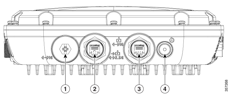
Figure 1. Models C9124AXI and C9124AXD Base Connectors and Ports

1

SFP port for uplink1. The SFP port only supports DC power IN.

If the port is not used, do not remove the covering plug. Otherwise, it might lead to water leaking into the AP

3

1 Gig PSE (PoE-OUT) Ethernet Port

2

2.5G mGig PD (PoE-IN) Ethernet port

4

Reset / Status LED

1 Use the SFP port or the Gigabit Ethernet port as the uplink port. However, if you do this, you cannot use the Ethernet port as a local client port. Connectors on the Sides

Note


Using SFP port for uplink uses wired0 MAC address as the source-MAC even though the packets get routed out from the wired1 interface. So all data packets going out of the AP, including the 802.1x packets use the wired0 MAC address.

The only exception is the CDP and LLDP packets that would use the wired1 MAC address as the source-MAC.


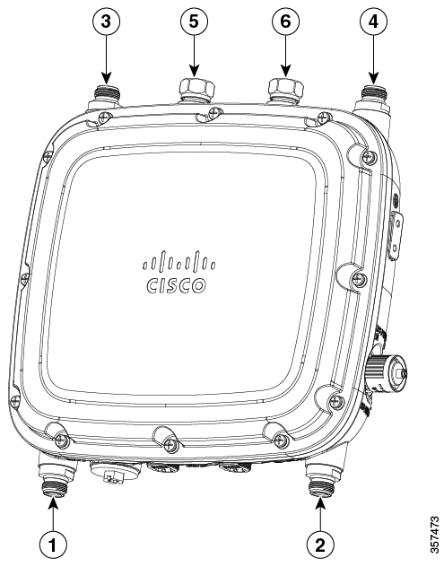
C9124AXE Connectors and Ports on the Top
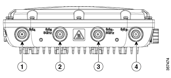
Figure 2. Model C9124AXE Top Connectors and Ports

1

Port 4

Connector Type: N–Female bulkhead

3

Port 5

This port supports 5-GHz antenna only.

This port supports SIA with 5-GHz band only.

Connector Type: N–Female bulkhead

2

Port 6

This port supports 5-GHz antenna only.

Connector Type: N–Female bulkhead

4

Port 3

This port supports SIA.

Connector Type: N–Female bulkhead

C9124AXE Connectors and Ports on the Base
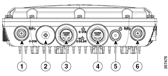
Figure 3. Model C9124AXE Base Connectors and Ports

1

Port 1

This port supports SIA.

Connetor Type: N–Female bulkhead

4

1 Gig PSE (PoE-OUT) Ethernet Port

2

SFP port for uplink2. The SFP port only supports DC power IN.

If the port is not used, do not remove the covering plug. Otherwise, it might lead to water leaking into the AP

5

Reset/Status LED

3

2.5G mGig PD (PoE-IN) Ethernet port

6

Port 2

Connetor Type: N–Female bulkhead

2 Use the SFP port or the Gigabit Ethernet port as the uplink port. However, if you do this, you cannot use the Ethernet port as a local client port.

Note


Using SFP port for uplink uses wired0 MAC address as the source-MAC even though the packets get routed out from the wired1 interface. So all data packets going out of the AP, including the 802.1x packets use the wired0 MAC address.

The only exception is the CDP and LLDP packets that would use the wired1 MAC address as the source-MAC.


Connectors and Ports on the Sides

Figure 4. Models C9124AXI, C9124AXD, and C9124AXE Left–Side and Right–Side Connectors and Ports

1

Console Port

2

Grounding Pad

3

DC Power In

C9124AXI (Internal Antenna) Model: Antenna Radiation Patterns

The following illustrations show the C9124AXI model with internal antenna radiation patterns:

Figure 5. C9124AXI–Dual-Band Antenna Radiation Pattern (2.4–GHz Azimuth)
Figure 6. C9124AXI–Dual-Band Antenna Radiation Pattern (2.4–GHz Elevation)
Figure 7. C9124AXI–Dual-Band Antenna Radiation Pattern (5–GHz Azimuth)
Figure 8. C9124AXI–Dual-Band Antenna Radiation Pattern (5–GHz Elevation)
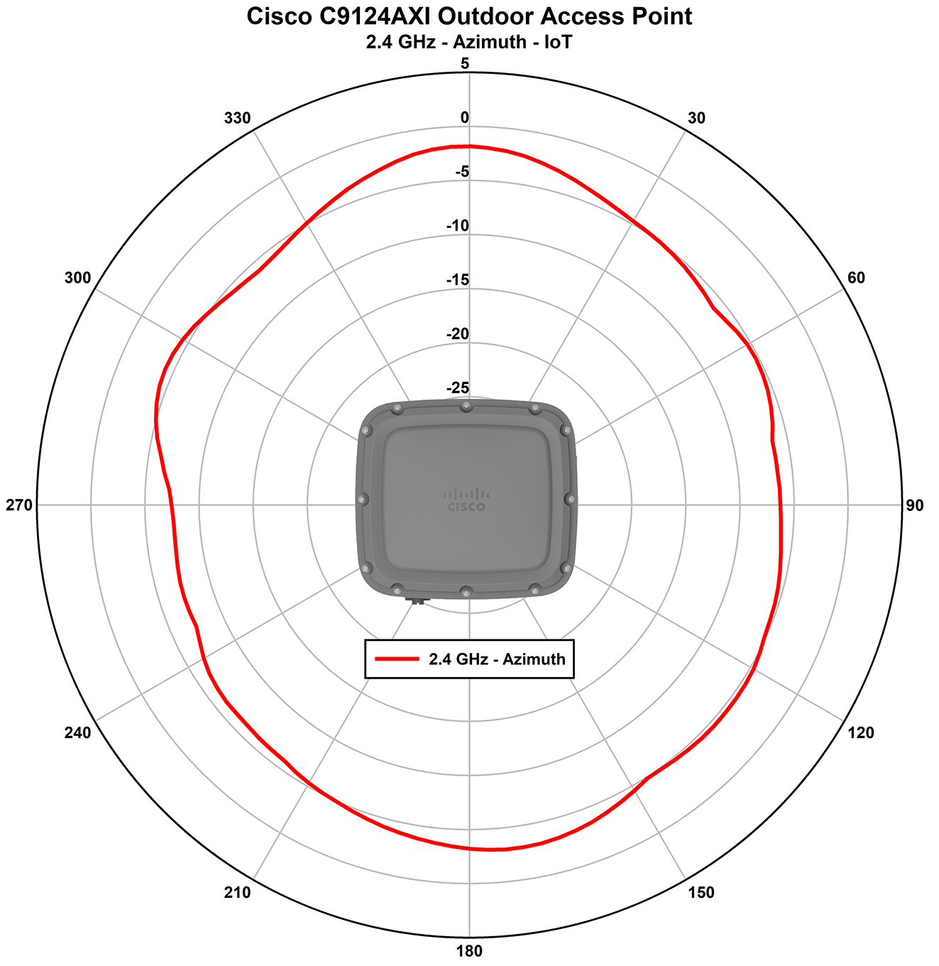
Figure 9. C9124AXI–IoT Antenna Radiation Pattern (2.4–GHz Azimuth)
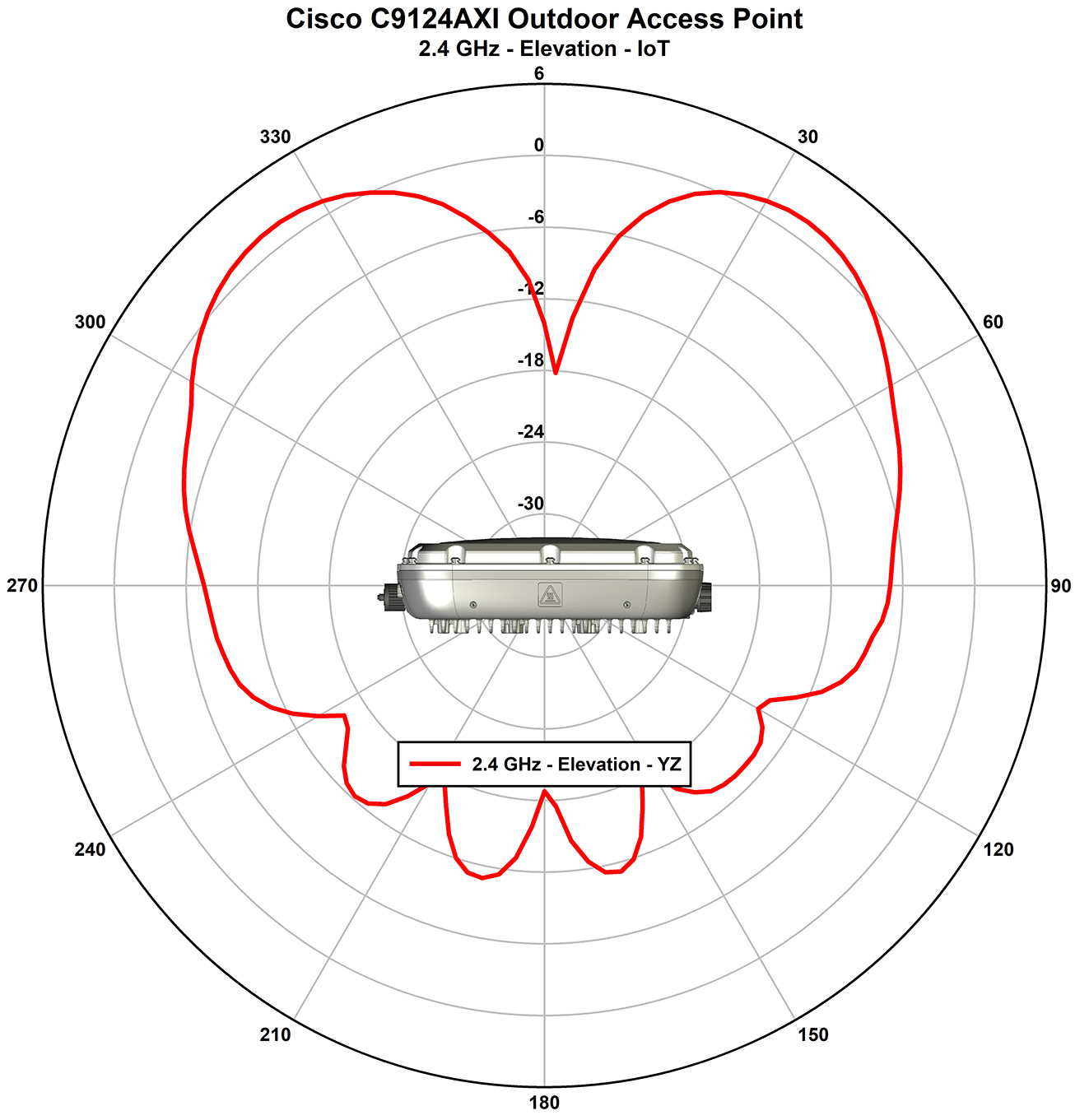
Figure 10. C9124AXI–IoT Antenna Radiation Pattern (2.4–GHz Elevation)
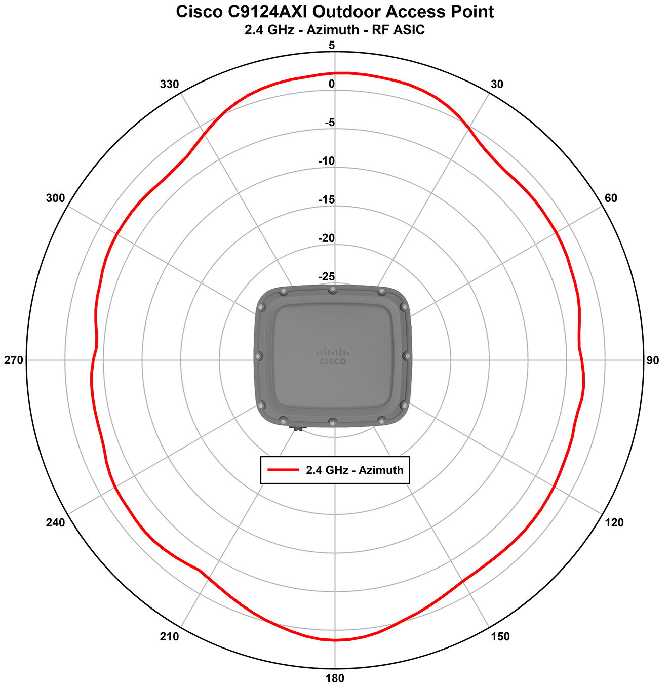
Figure 11. C9124AXI–AUX RF ASIC Antenna Radiation Pattern (2.4–GHz Azimuth)
Figure 12. C9124AXI–AUX RF ASIC Antenna Radiation Pattern (2.4–GHz Elevation)
Figure 13. C9124AXI–AUX RF ASIC Antenna Radiation Pattern (5–GHz Azimuth)
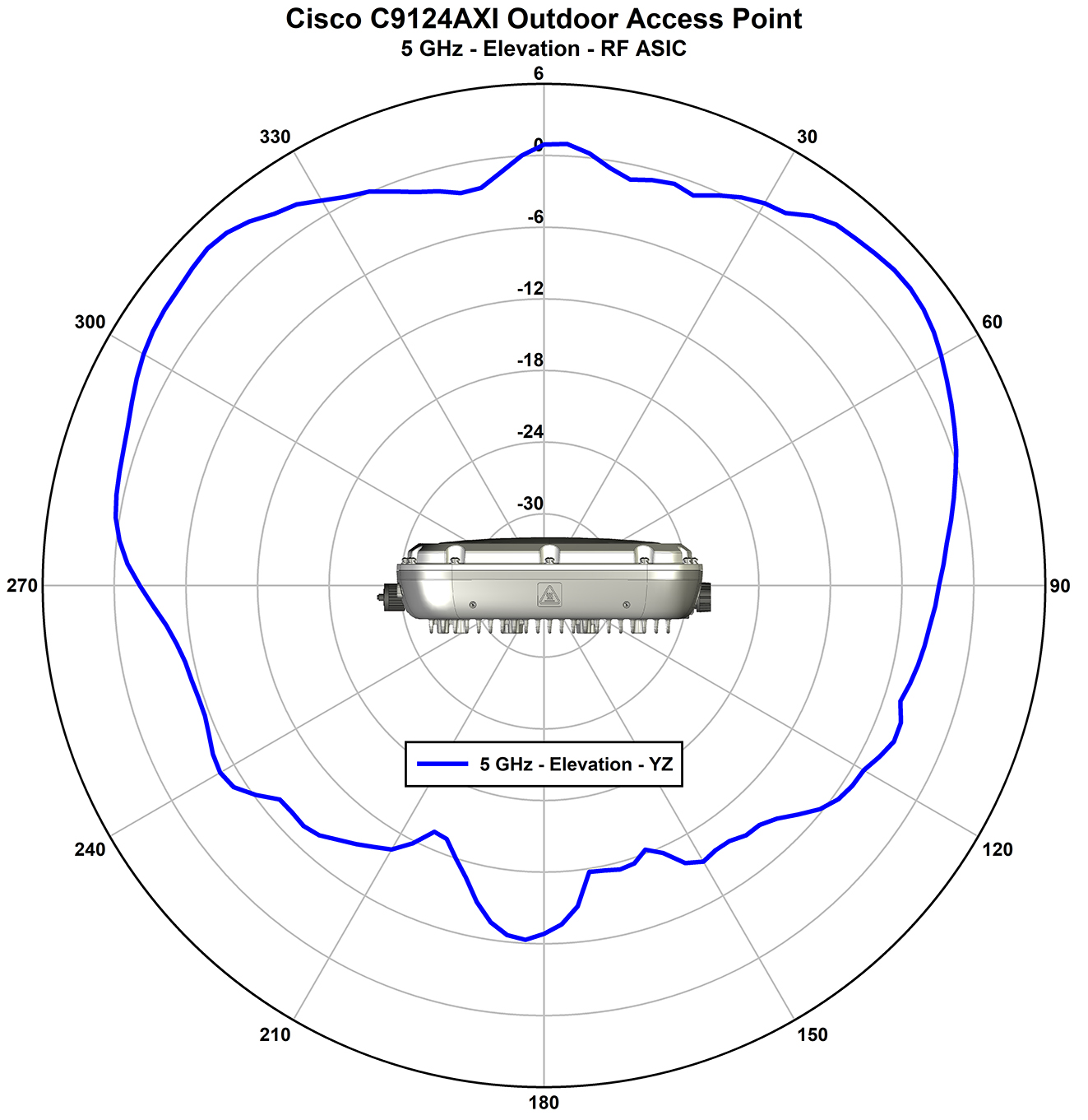
Figure 14. C9124AXI–AUX RF ASIC Antenna Radiation Pattern (5–GHz Elevation)

C9124AXD (Directional Antenna) Model: Antenna Radiation Patterns

The C9124AXD model with directional internal antenna has its radio radiation patterns shown in the following images:

Figure 15. C9124AXD–Dual-Band Antenna Radiation Pattern (2.4–GHz Azimuth)
Figure 16. C9124AXD–Dual-Band Antenna Radiation Pattern (2.4–GHz Elevation)
Figure 17. C9124AXD–Dual-Band Antenna Radiation Pattern (5–GHz Azimuth)
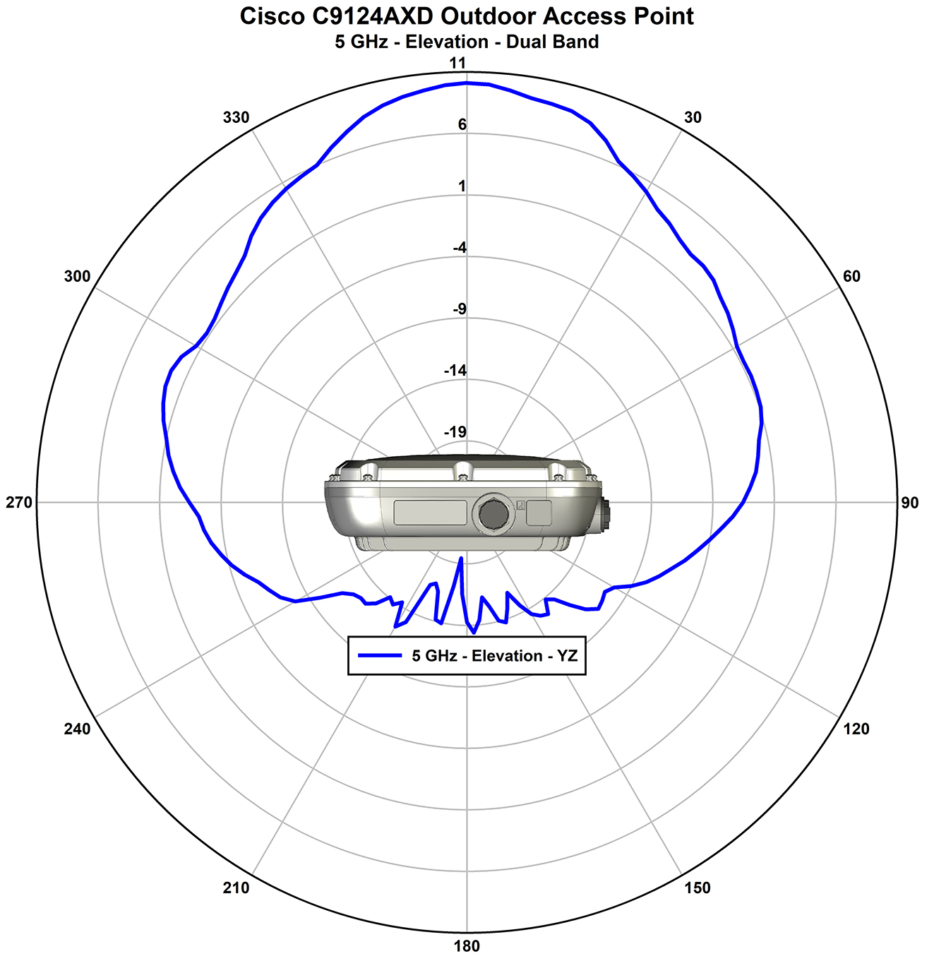
Figure 18. C9124AXD–Dual-Band Antenna Radiation Pattern (5–GHz Elevation)
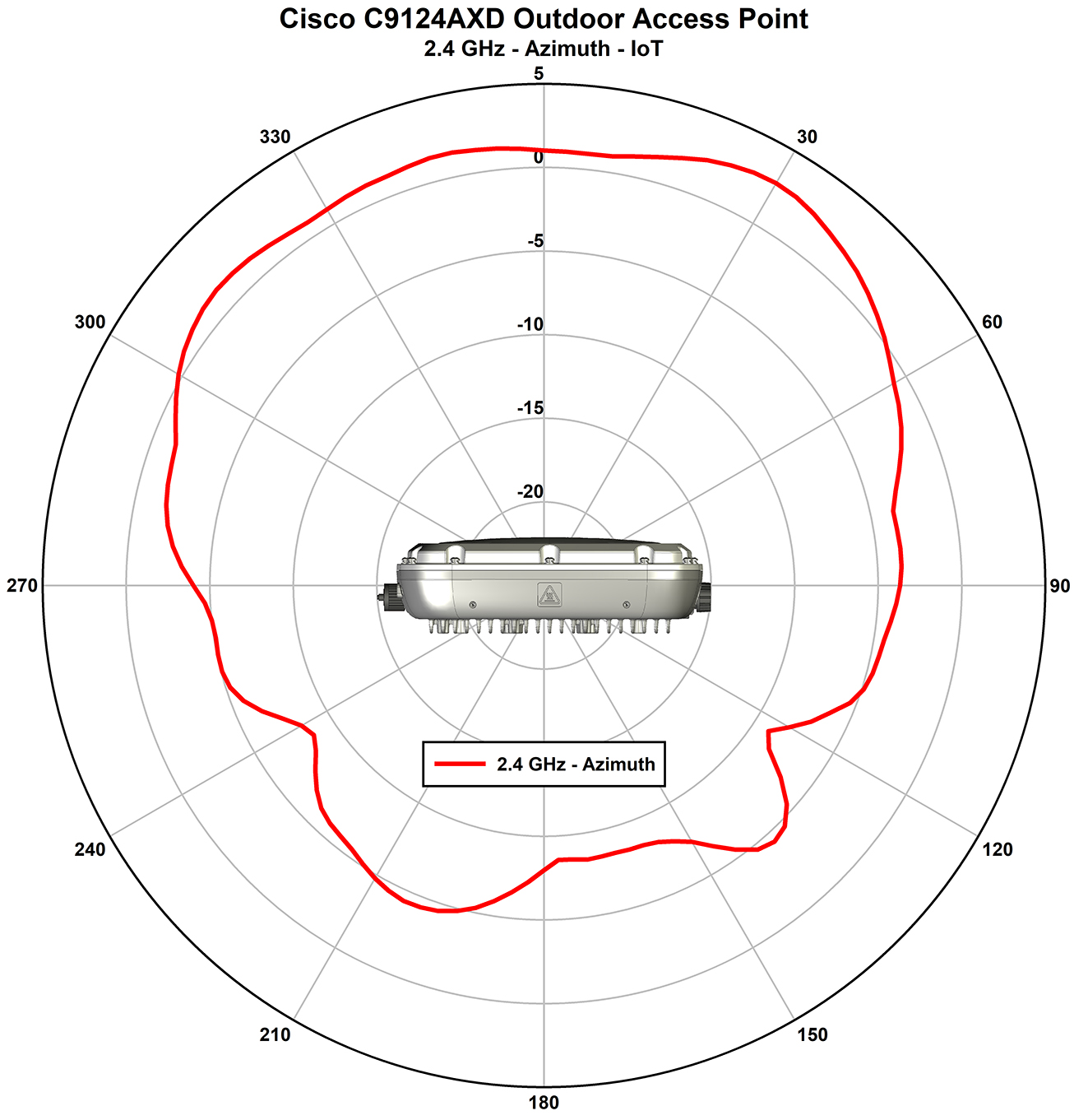
Figure 19. C9124AX–IoT Antenna Radiation Pattern (2.4–GHz Azimuth)
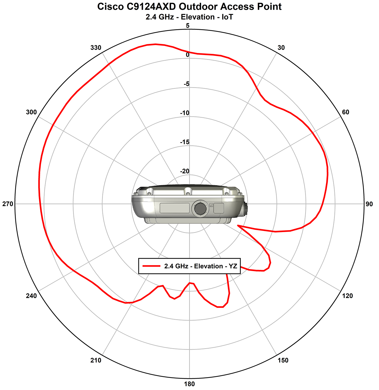
Figure 20. C9124AX–IoT Antenna Radiation Pattern (2.4–GHz Elevation)
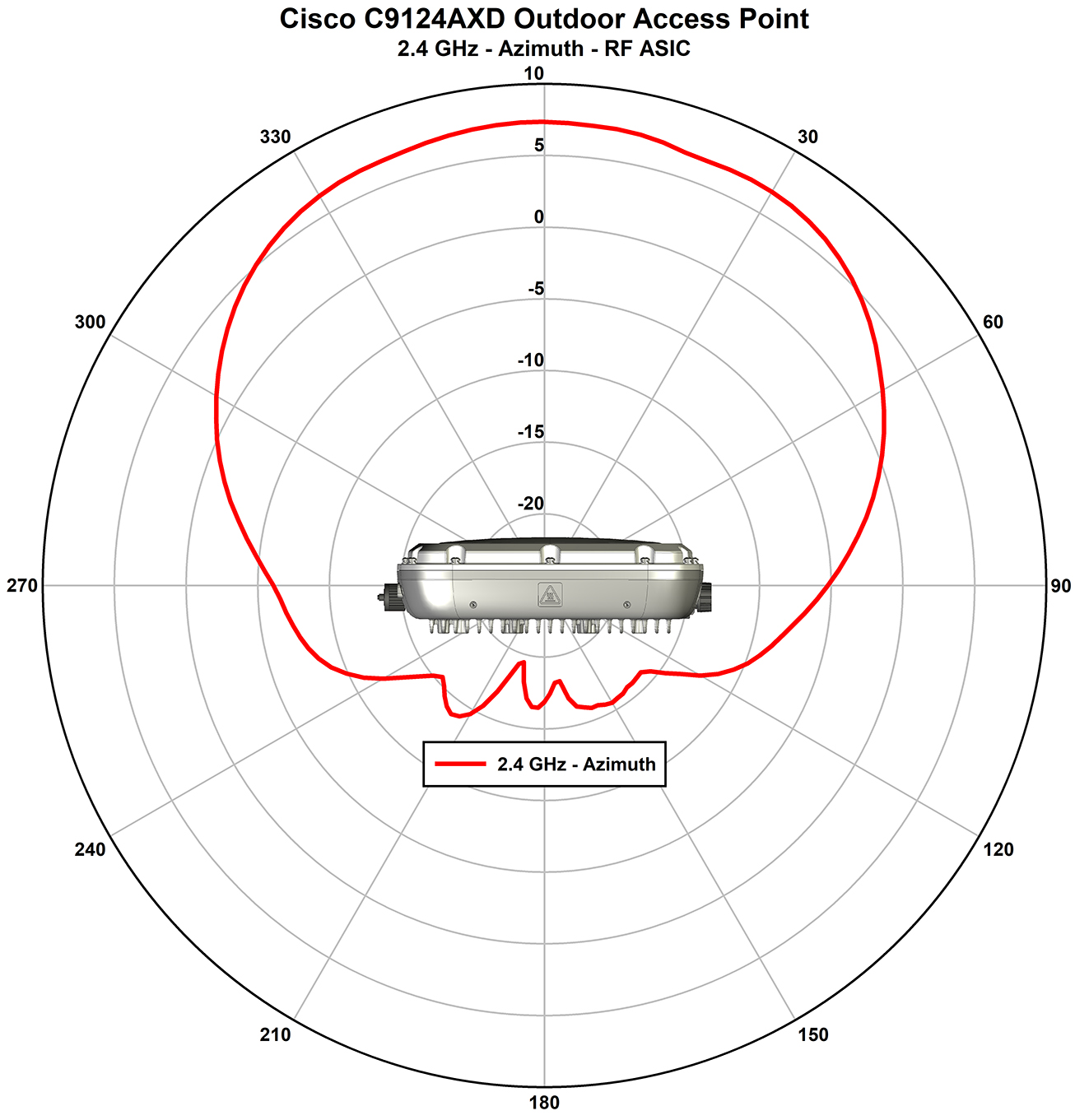
Figure 21. C9124AXD–AUX RF ASIC Antenna Radiation Pattern (2.4–GHz Azimuth)
Figure 22. C9124AXD–AUX RF ASIC Antenna Radiation Pattern (2.4–GHz Elevation)
Figure 23. C9124AXD–AUX RF ASIC Antenna Radiation Pattern (5–GHz Azimuth)
Figure 24. C9124AXD–AUX RF ASIC Antenna Radiation Pattern (5–GHz Elevation)

C9124AXE (External Antenna) Model: Antenna Radiation Patterns

The following illustrations show the C9124AXE model with external antenna radiation patterns:

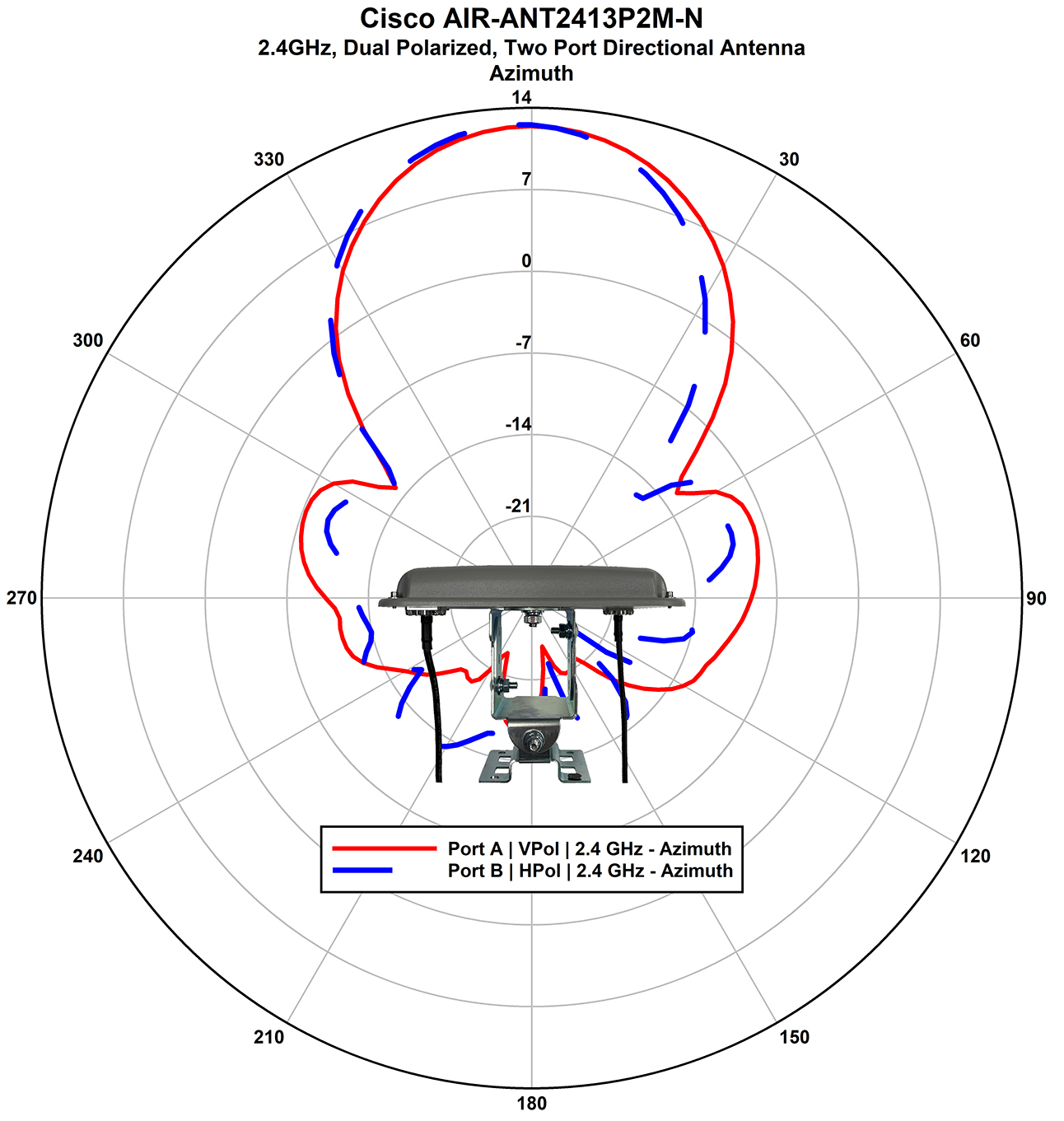
Figure 25. AIR-ANT2413P2M-N: 2.4–GHz Dual-Polarized Two Port Directional Antenna Radiation Pattern (Azimuth)
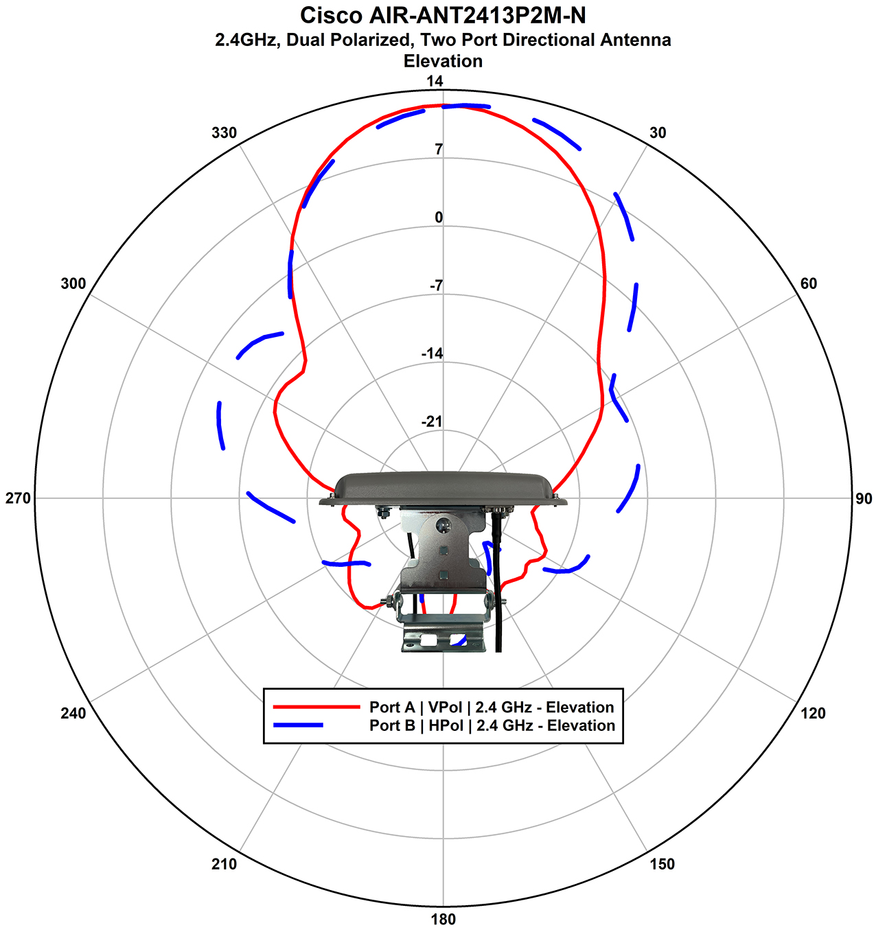
Figure 26. AIR-ANT2413P2M-N: 2.4–GHz Dual-Polarized Two Port Directional Antenna Pattern (Elevation)
Figure 27. AIR-ANT2450V-N: 2.4–GHz Omnidirectional Antenna Radiation Pattern (Azimuth)
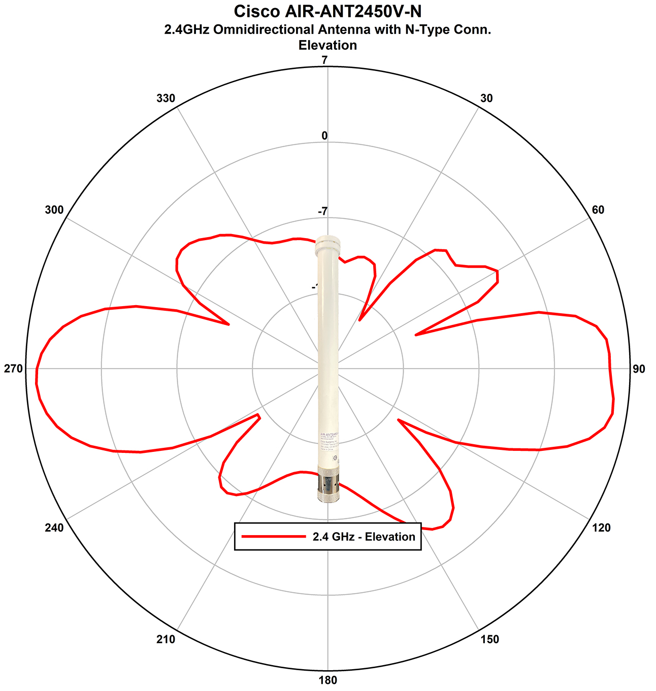
Figure 28. AIR-ANT2450V-N: 2.4–GHz Omnidirectional Antenna Radiation Pattern (Elevation)
Figure 29. AIR-ANT2480V-N: 2.4–GHz Omnidirectional Antenna Radiation Pattern (Azimuth)
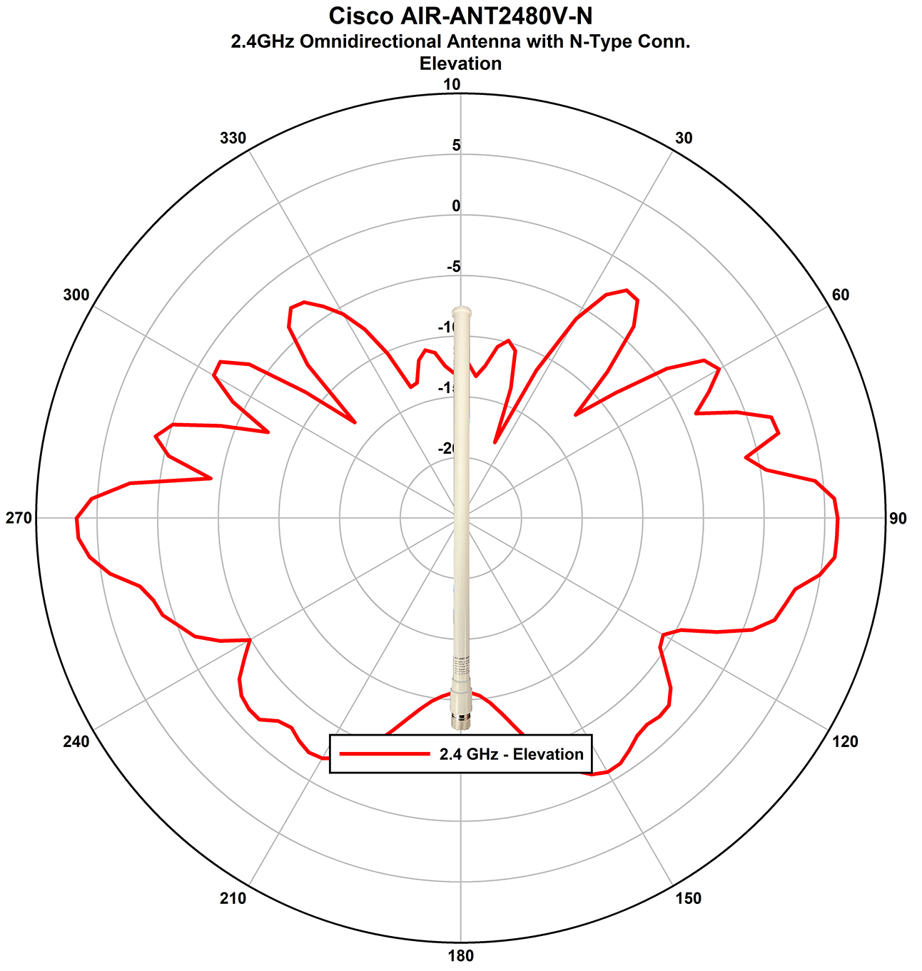
Figure 30. AIR-ANT2480V-N: 2.4–GHz Omnidirectional Antenna Radiation Pattern (Elevation)
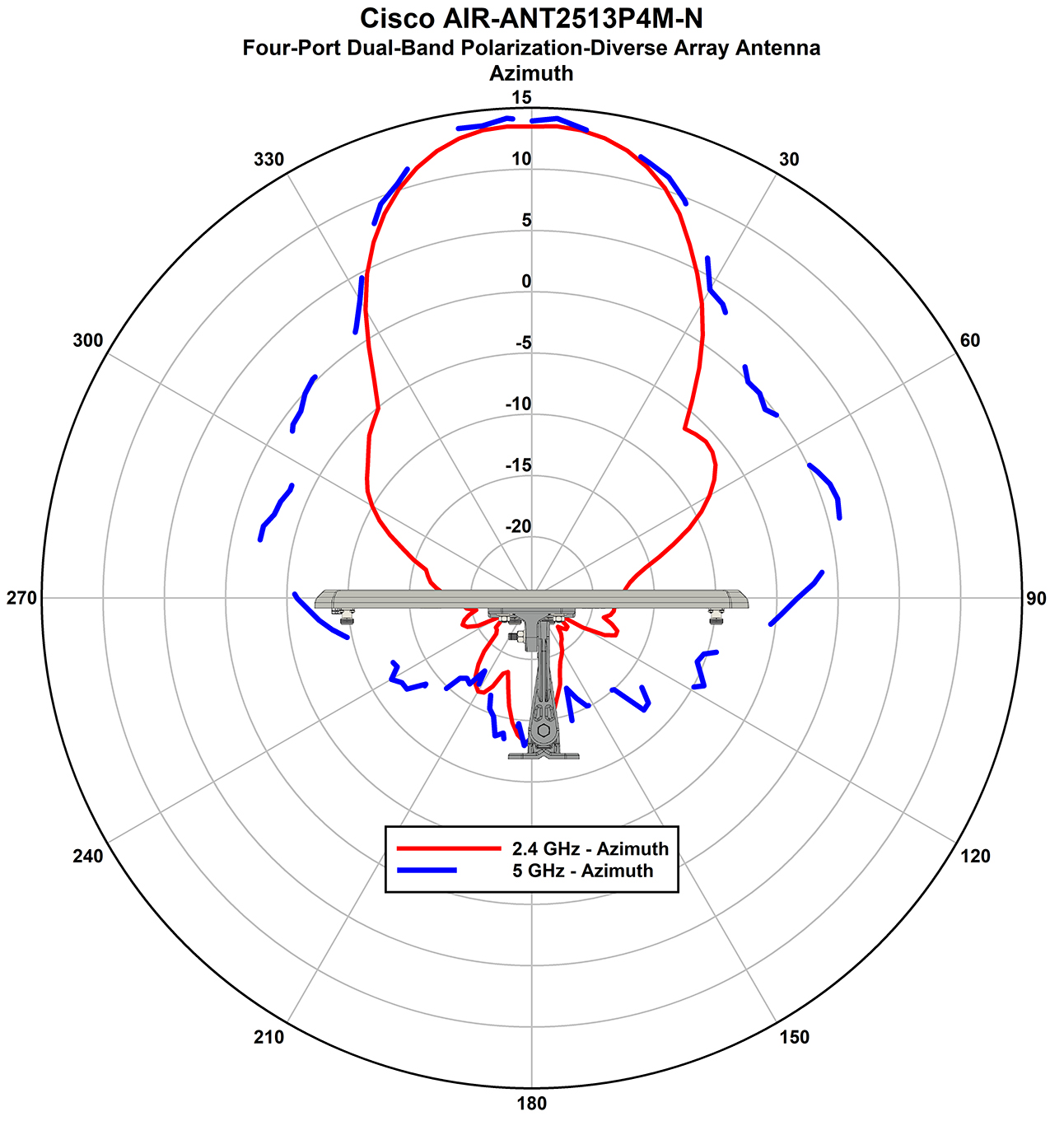
Figure 31. AIR-ANT2513P4M-N: Four-Port Dual-Band Polarization Diverse-Array Radiation Pattern (Azimuth)
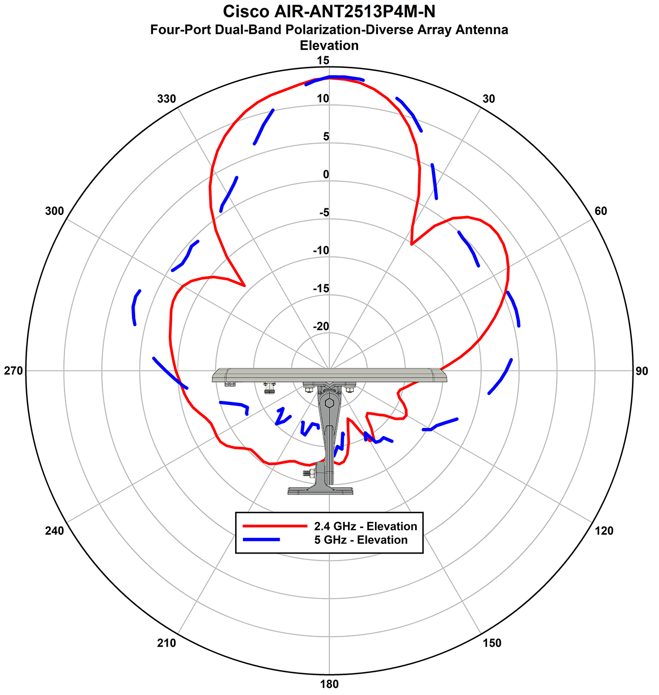
Figure 32. AIR-ANT2513P4M-N: Four-Port Dual-Band Polarization Diverse-Array Antenna Radiation Pattern (Elevation)
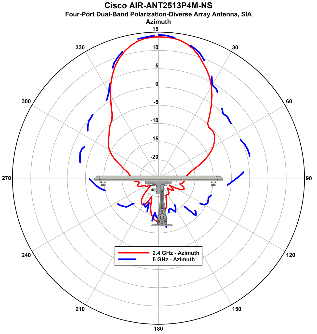
Figure 33. AIR-ANT2513P4M-NS: Four-Port Dual-Band Polarization Diverse-Array Antenna SIA Radiation Pattern (Azimuth)
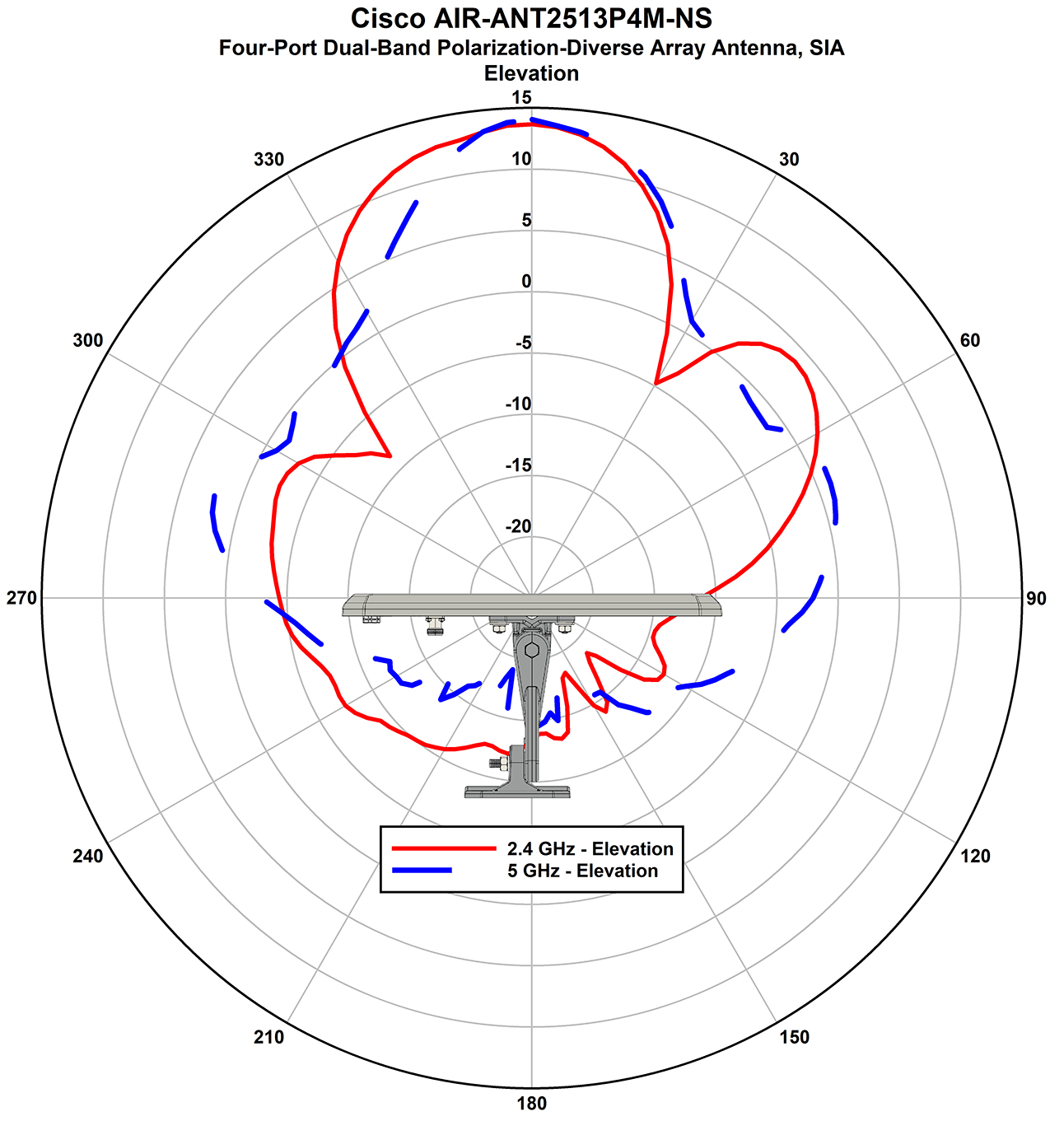
Figure 34. AIR-ANT2513P4M-NS: Four-Port Dual-Band Polarization Diverse-Array Antenna SIA Radiation Pattern (Elevation)
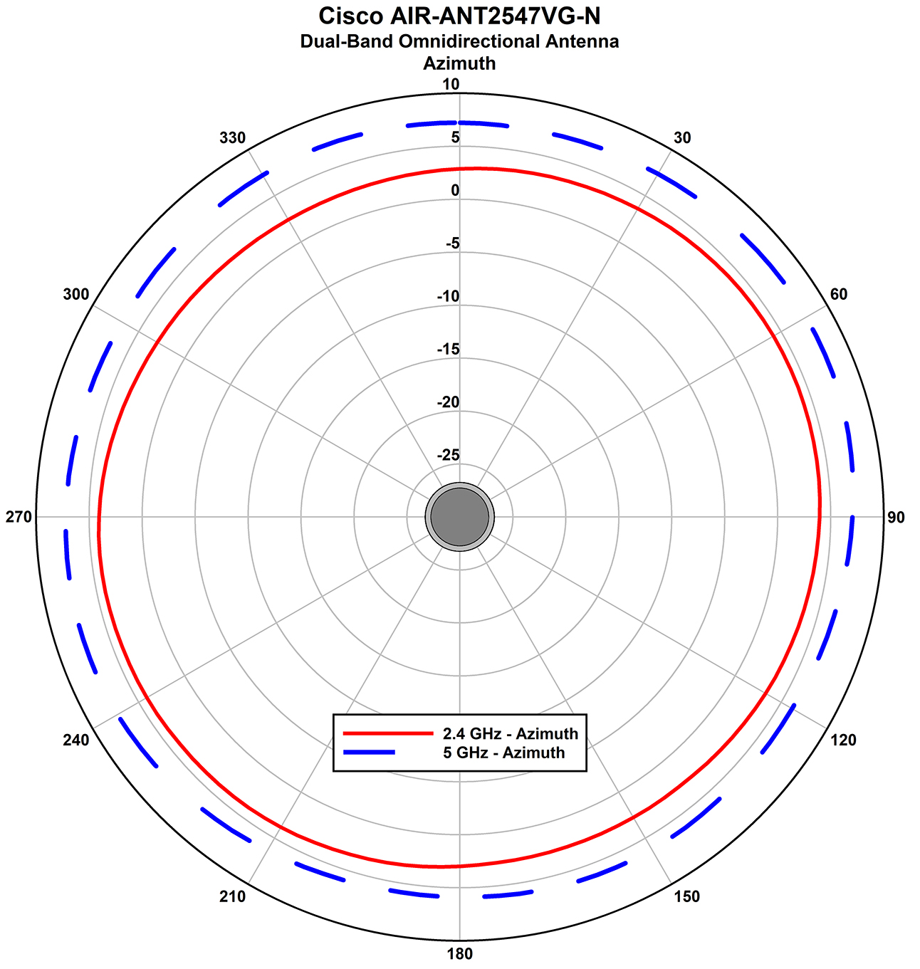
Figure 35. AIR-ANT2547VG-N: Dual-Band Omnidirectional Antenna Radiation Pattern (Azimuth)
Figure 36. AIR-ANT2547VG-N: Dual-Band Omnidirectional Antenna Radiation Pattern (Elevation)
Figure 37. AIR-ANT2547VG-NS: Dual-Band Omnidirectional Antenna Radiation Pattern (Azimuth)
Figure 38. AIR-ANT2547VG-NS: Dual-Band Omnidirectional Antenna Radiation Pattern (Elevation)
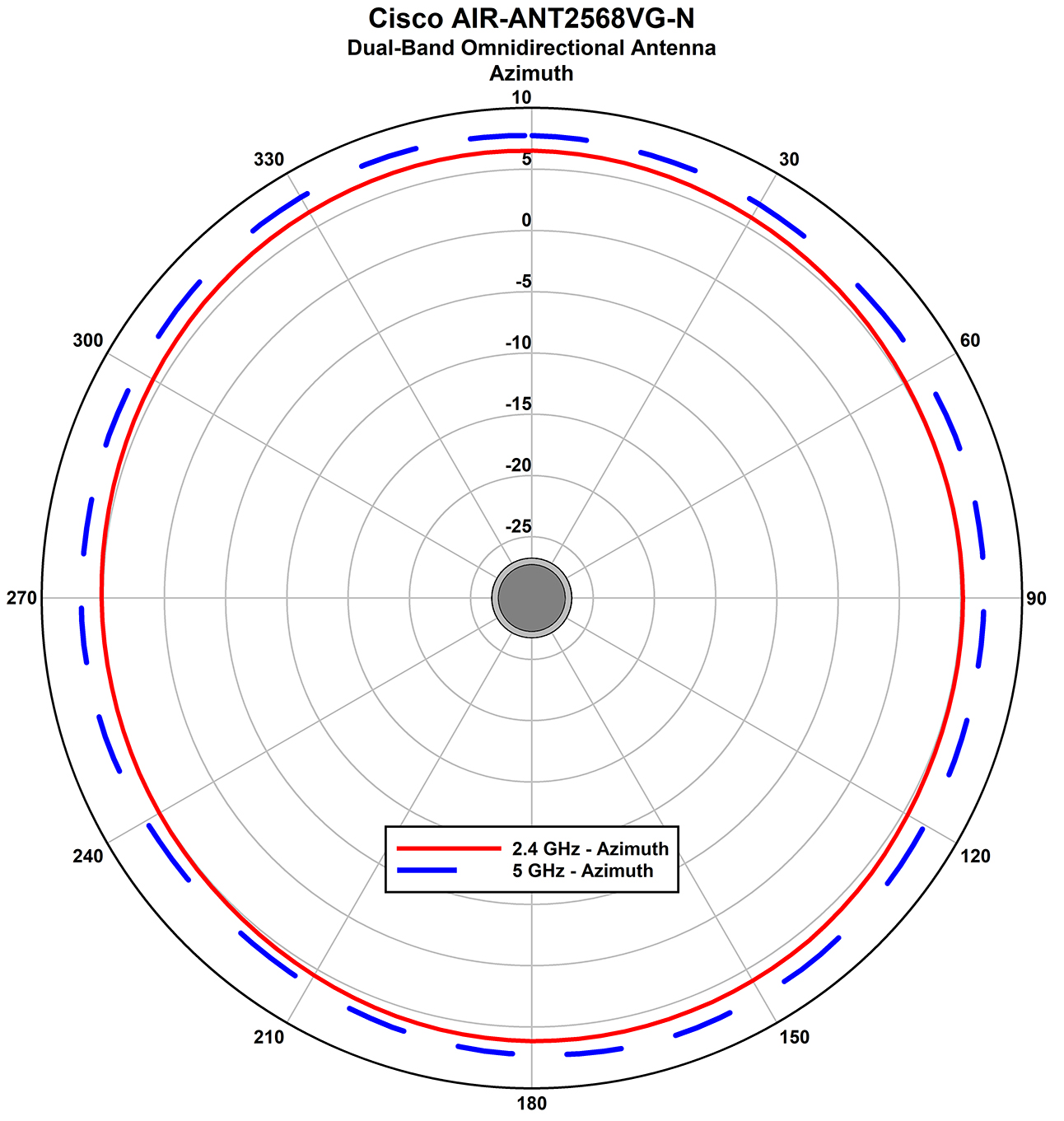
Figure 39. AIR-ANT2568VG-N: Dual-Band Omnidirectional Antenna Radiation Pattern (Azimuth)
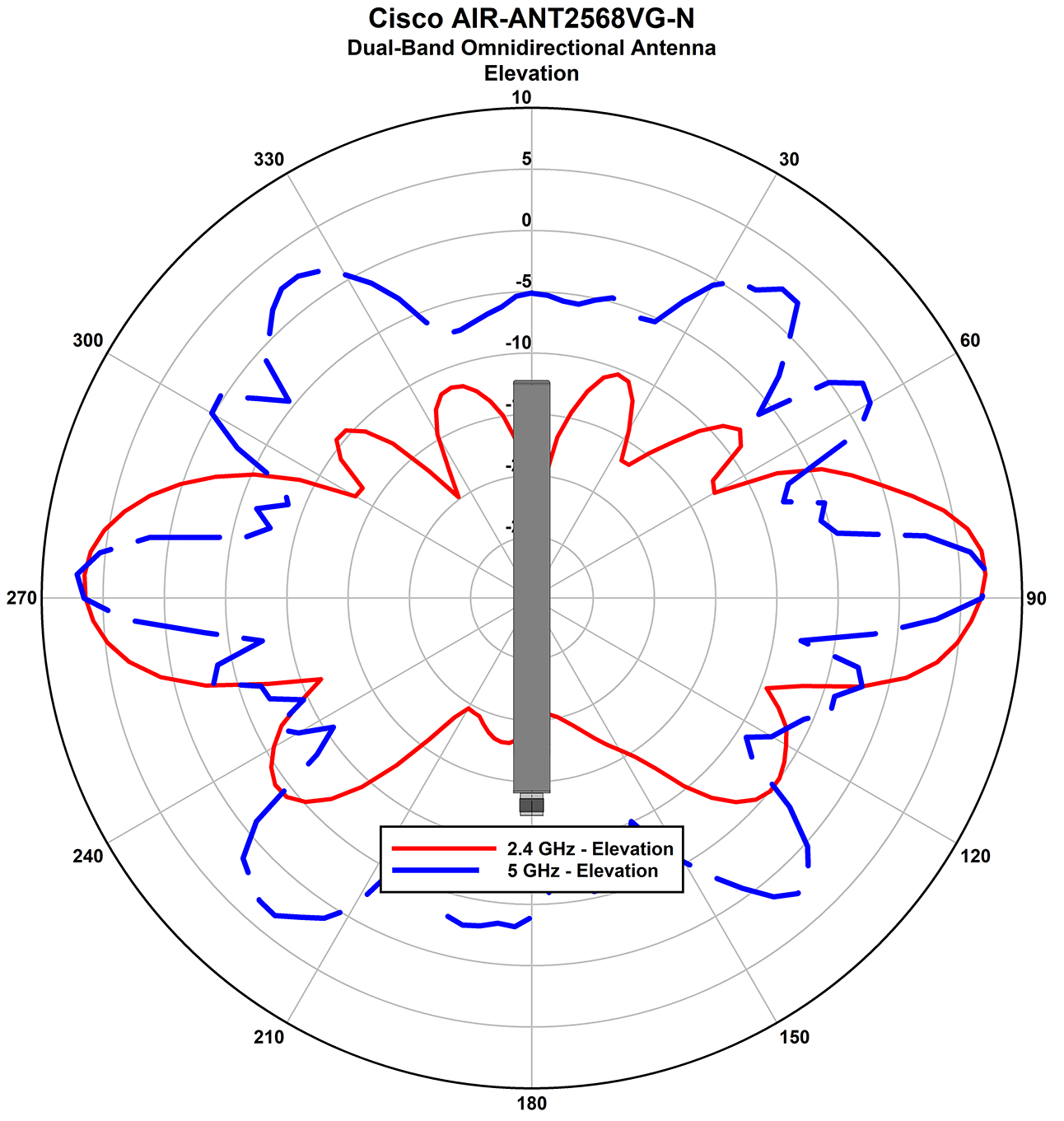
Figure 40. AIR-ANT2568VG-N: Dual-Band Omnidirectional Antenna Radiation Pattern (Elevation)
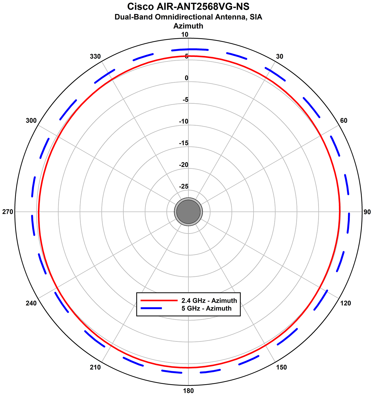
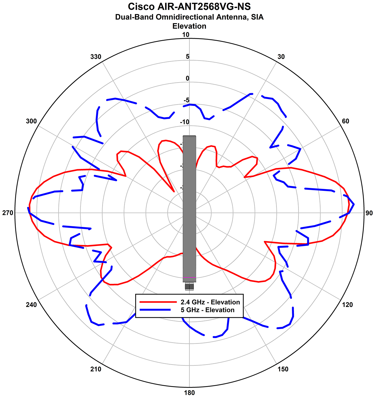
Figure 41. AIR-ANT2568VG-NS: Dual-Band Omnidirectional Antenna Radiation Pattern (Azimuth)
Figure 42. AIR-ANT2568VG-NS: Dual-Band Omnidirectional Antenna Radiation Pattern (Elevation)
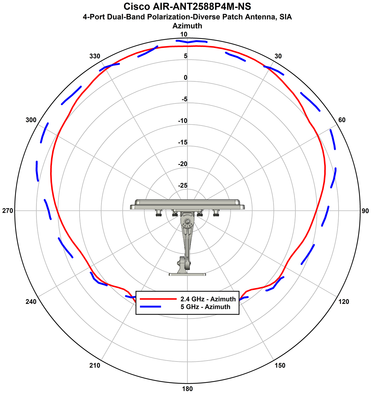
Figure 43. AIR-ANT2588P4M-NS: 4-Port Dual-Band Polarization-Diverse Patch Antenna, SIA Radiation Pattern (Azimuth)
Figure 44. AIR-ANT2588P4M-NS: 4-Port Dual-Band Polarization-Diverse Patch Antenna, SIA Radiation Pattern (Elevation)
Figure 45. AIR-ANT5114P2M-N: 2-Port 5-GHz Dual Polarized Directional Antenna Radiation Pattern (Azimuth)
Figure 46. AIR-ANT5114P2M-N: 2-Port 5-GHz Dual Polarized Directional Antenna Radiation Pattern (Elevation)
Figure 47. AIR-ANT5180V-N: 5–GHz Omnidirectional Antenna Radiation Pattern (Azimuth)
Figure 48. AIR-ANT5180V-N: 5–GHz Omnidirectional Antenna Radiation Pattern (Elevation)

Supported External Antennas

The following table shows the external antennas supported by the C9124AXE access point:

1

Port 1

Supports 2.4-GHz and 5-GHz bands

Supports SIA

Connector Type: N–Female bulkhead

4

Port 4

Supports 2.4-GHz and 5-GHz bands

Connector Type: N–Female bulkhead

2

Port 2

Supports 2.4-GHz and 5-GHz bands

Connector Type: N–Female bulkhead

5

Port 5

Supports 5-GHz band only

Supports SIA

Connector Type: N–Female bulkhead

3

Port 3

Supports 2.4-GHz and 5-GHz bands

Supports SIA

Connector Type: N–Female bulkhead

6

Port 6

Supports 5-GHz band only

Connector Type: N–Female bulkhead

Table 1. 9124AXE Access Point Supported External Antennas

PID

Antenna Gain (dBi)

Antenna Name

2.4–GHz

5–GHz

AIR-ANT2547V-N

4

7

Cisco Aironet Dual-Band Omnidirectional Colinear Array Antenna (White)

Connectors: N-Male

AIR-ANT2547VG-N

4

7

Cisco Aironet Dual-Band Omnidirectional Colinear Array Antenna (Gray)

Connectors: N-Male

AIR-ANT2547VG-NS

4

7

Cisco Aironet Dual-Band Omnidirectional Colinear Array (Gray), Self-Identifying Antenna

Connectors: N-Male

AIR-ANT2588P4M-NS=

8

8

Cisco Aironet 2.4–GHz/5–GHz 8–dBi 4-Element Dual-Polarized Patch Self-Identifying Antenna

Connectors: N-Female Bulkhead

AIR-ANT2450V-N=

5

Cisco Aironet 5–dBi Omnidirectional Antenna

AIR-ANT2480V-N=

8

Cisco Aironet 8–dBi Omnidirectional Antenna

AIR-ANT2413P2M-N=

13

Cisco Aironet 2.4–GHz 13–dBi Directional Antenna

AIR-ANT2413P2M-NS=

13

Cisco Aironet 2.4–GHz 13–dBi Directional Antenna, Self-Identifying

AIR-ANT5180V-N=

8

Cisco Aironet 8–dBi Omnidirectional Antenna

AIR-ANT5114P2M-N=

14

Cisco Aironet 5–GHz 14–dBi Directional Antenna

AIR-ANT5114P2M-NS=

14

Cisco Aironet 5–GHz 14–dBi Directional Antenna, Self-Identifying

AIR-ANT2568VG-N

6

8

Cisco Aironet Dual-Band Omnidirectional Antenna

AIR-ANT2568VG-NS

6

8

Cisco Aironet Dual-Band Omnidirectional Antenna, Self-Identifying

AIR-ANT2513P4M-N=

13

13

Cisco Aironet Four-Port Dual-Band Polarization-Diverse Array Antenna

AIR-ANT2513P4M-NS=

13

13

Cisco Aironet Four-Port Dual-Band Polarization-Diverse ArrayAntenna, Self-Identifying

For installation instructions and detailed information on any of these antennas, refer to the antenna guide at:

http://www.cisco.com/c/en/us/support/wireless/aironet-antennas-accessories/products-installation-guides-list.html

Follow all safety precautions when installing the antennas. For information on safety, see Safety Precautions when Installing Antennas.

Non-Cisco Antennas

Cisco does not support any third-party antennas. RF connectivity and compliance of third party antennas is the user’s responsibility. Cisco does not recommend any third-party antennas, and Cisco Technical Assistance Center will not be able to provide any support for third-party antennas. Cisco’s FCC Part 15 compliance is only guaranteed with Cisco antennas or antennas that are of the same design and gain as Cisco antennas.

Cisco Flexible Antenna Port

The Cisco Flexible Antenna Port feature on the C9124AXE access points allows support for either dual-band or single-band antennas on the same AP. This is configurable using a CLI command from the wireless LAN controller.

Power Sources

The Cisco Catalyst 9124AX Series Outdoor Access Point is supported on these power sources:


DANGER


Connect the unit only to DC power source that complies with the safety extra-low voltage (SELV) requirements in IEC 60950 based safety standards. Statement 1033


Caution


For PoE options and their corresponding modes of operation, see Table 1.

Caution


When the AP is installed outdoors or in a wet or damp location, the AC branch circuit powering the AP should be provided with ground fault protection (GFCI), as required by Article 210 of the National Electrical Code (NEC).

Power Adapters

The Cisco Catalyst 9124AX Series Outdoor Access Point supports the following DC power adapters::

  • PID AIR-PWRADPT-RGD2=

Power Injectors

The Cisco Catalyst 9124AX Series Outdoor Access Point supports the following power injectors:

  • AIR-PWRINJ-60RGD1=

  • AIR-PWRINJ-60RGD2=

  • AIR-PWRINJ7=

  • AIR-PWRINJ6=


DANGER


To reduce the risk of fire, use only No. 24 AWG or larger telecommunications line cord. Statement 1023


Caution


When the AP is installed outdoors or in a wet or damp location, the AC branch circuit powering the AP should be provided with ground fault protection (GFCI), as required by Article 210 of the National Electrical Code (NEC).

Ethernet (PoE) Ports

The AP supports an Ethernet uplink port (also for PoE-In). The Ethernet uplink port on the AP uses an RJ-45 connector (with weatherproofing) to link the AP to the 100BASE-T, 1000BASE-T, or 2.5GBASE-T network. The Ethernet cable is used to send and receive Ethernet data and optionally supply inline power from the power injector or a suitably powered switch port.


Tip


The AP senses the Ethernet and power signals, and automatically switch internal circuitry to match the cable connections.

DANGER


To reduce the risk of fire, use only No. 24 AWG or larger telecommunication line cord. Statement 1023


The Ethernet cable must be a shielded, outdoor rated, Category 5e (CAT 5e) or better cable. The AP senses the Ethernet and power signals and automatically switches internal circuitry to match the cable connections.