Recycling Compute Node Components

This chapter contains the following topics:

Compute Node Recycling Overview

This chapter documents the procedures to disassemble key compute node components for recycling and e-waste. When recycling your Cisco UCS hardware, always make sure to follow local e-waste and recycling regulations.


Note


For Recyclers Only! The procedures in this chapter are not standard field-service options. These procedures are for recyclers who will be reclaiming the electronics for proper disposal to comply with local eco design and e-waste regulations.


To disassemble compute node component parts, see the following topics:

Removing the Trusted Platform Module (TPM)

The TPM module is attached to the printed circuit board assembly (PCBA). You must disconnect the TPM module from the PCBA before recycling the PCBA. The TPM module is secured to a threaded standoff by a tamper-resistant screw. If you do not have the correct tool for the screw, you can use a pair of pliers to remove the screw.


Caution


Removing the TPM destroys the part so that it cannot be reinstalled or reused!


Before you begin


Caution


For Recyclers Only! This procedure is not a standard field-service option. This procedure is for recyclers who will be reclaiming the electronics for proper disposal to comply with local eco design and e-waste regulations.


To remove the Trusted Platform Module (TPM), the following requirements must be met for the compute node:

Procedure


Step 1

If the rear mezzanine card is installed, use a #2 screwdriver to remove the four captive screws, then remove the card.

Step 2

Locate the TPM module.

Step 3

Using the pliers, grip the head of the TPM and turn it counterclockwise until it releases.

Step 4

Remove the TPM module and dispose of it properly.


What to do next

Remove and dispose of the PCB Assembly. See Recycling the Primary Motherboard PCBA.

Recycling the Component PCB Assemblies (PCBAs)

The compute node has various printed circuit board assemblies (PCBAs) that must be recycled to comply with your local e-waste laws. The main motherboard PCB for both the primary and secondary as well as some smaller PCBs must be recycled.

Always comply with your local regulations governing recycling and e-waste.

Use the following procedures to disassemble the appropriate PCBAs.

Recycling the Secondary Motherboard PCBA

The secondary has a PCBA that is connected to the compute node's faceplate and sheet metal tray. You must disconnect the PCBA from the faceplate and tray to recycle the PCBA. The secondary is attached to the sheet metal tray be the following:

  • Nineteen T10 Torx screws

  • Six T8 Torx screws

  • Twelve T20 nuts

For this procedure you will need a T8, T10, and T20 screwdriver.

You will need to recycle both the secondary and primary to recycle the compute node.

Before you begin


Note


For Recyclers Only! This procedure is not a standard field-service option. This procedure is for recyclers who will be reclaiming the electronics for proper disposal to comply with local eco design and e-waste regulations.


Procedure


Step 1

If you have not already removed the secondary's top cover, remove it now.

See Removing a Compute Node Cover.

Step 2

Remove the secondary's front mezzanine module.

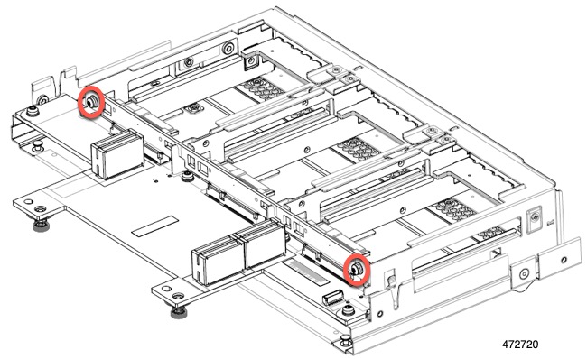
  1. Using a T8 screwdriver, remove the screws on the sidewall.

    There are two screws per side.

  2. When all four screws are removed, lift the secondary front mezzanine module to disconnect it from the motherboard.

    For additional information, see Removing the Front Mezzanine Module.

Step 3

Remove the DIMMs or DIMM blanks, by pressing outward on the release buttons on each DIMM slot, and simultaneously lifting up on the DIMM.

Step 4

Remove each CPU and its heatsink.

See Removing the CPU and Heatsink.

Step 5

Using a T10 screwdriver, remove the screws and power adapter.

Step 6

Using a T8 screwdriver, remove the screws on the sidewall.

There is one screw per side.

Step 7

Using a T10 screwdriver, remove the Torx nuts from the top of the rear mezzanine frame, then remove the rear mezzanine frame.

Step 8

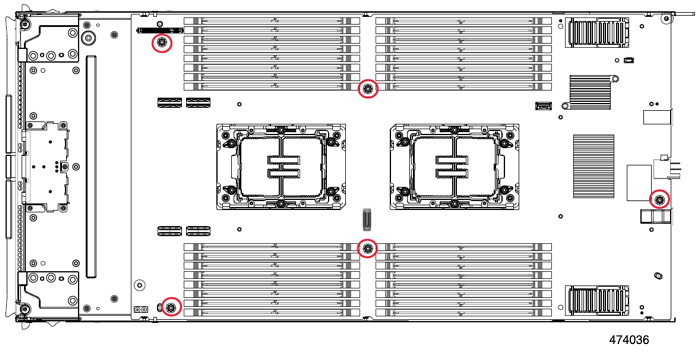
Using a T10 screwdriver, remove the two standoffs next to CPU 3, which is nearest to the front of the compute node.

Step 9

Using a T10 screwdriver, remove the Torx screws that secure the secondary PCB to the midframe.

Step 10

Using a T20 screwdriver, loosen the captive Torx nuts that hold each CPU bolster plate, then remove the plates.

There are six nuts for each plate.

Step 11

Grasp the secondary PCB along the edges and lift it up to disconnect it.

Note


You will feel some resistance when lifting the PCB, This resistance is normal. It occurs because you have to separate the board-to-board connectors that connect the primary and secondary PCBs.

Step 12

Using a T10 screwdriver, remove the two screws that secure the primary's PCB to the midframe.

Each screw is accessible through a hole in the midframe.

Step 13

Recycle the sheet metal and motherboard in compliance with your local recycling and e-waste regulations.


What to do next

Continue by Recycling the Primary Motherboard PCBA,

Recycling the Primary Motherboard PCBA

The primary has a PCBA that is connected to the compute node's faceplate and sheet metal tray. You must disconnect the PCBA from the faceplate and tray to recycle the PCBA. Each primary is attached to the sheet metal tray by the following:

  • Thirteen T10 screws

  • Twelve T20 nuts

  • Two T8 screws.

For this procedure you will need a T8, T10, and T20 screwdriver.

You will need to recycle both the secondary and primary to recycle the compute node.

Before you begin


Note


For Recyclers Only! This procedure is not a standard field-service option. This procedure is for recyclers who will be reclaiming the electronics for proper disposal to comply with local eco design and e-waste regulations.


Important


The secondary must already be disassembled and removed from the compute node before attempting this procedure. If you have not removed the secondary, remove it now. See Recycling the Secondary Motherboard PCBA.


Procedure


Step 1

Position the compute node so that the primary is facing up.

Step 2

If you have not already removed the top cover, remove it now.

See Removing a Compute Node Cover.

Step 3

Remove the FRU components from the primary as needed.

  1. (Optional) Remove the front mezzanine module.

    See Removing the Front Mezzanine Module.

  2. (Optional) Remove the screws, then remove the M.2 RAID Controller.

    See Removing the M.2 RAID Controller Module or NVMe Pass-Through Module.

  3. (Optional) If the bridge card is installed, remove it.

    See Removing the Bridge Card.

  4. (Optional) If the rear mezzanine card is installed, use a #2 screwdriver to remove the four captive screws, then remove the card.

  5. (Optional) If the MLOM VIC is installed, remove it.

    See Removing the mLOM.

  6. Remove the DIMMs or DIMM blanks, by pressing outward on the release buttons on each DIMM slot, and simultaneously lifting up on the DIMM.

  7. (Optional) If the CPUs and heatsinks are installed, remove each CPU.

    See Removing the CPU and Heatsink.

  8. Remove the TPM.

    See Removing the Trusted Platform Module (TPM).

Step 4

Using a T8 screwdriver, remove the screws on the sidewall.

There is one screw per side.

Step 5

Using a T10 screwdriver, remove the Torx nuts from the top of the rear mezzanine frame, then remove the primary's rear mezzanine frame.

Step 6

Using a T10 screwdriver, remove the two standoffs next to CPU 1, which is nearest to the front of the compute node.

Step 7

Using a T10 screwdriver, remove the Torx screws that secure the primary PCB to the midframe.

Step 8

Using a T20 screwdriver, loosen the captive Torx nuts that hold each CPU bolster plate, then remove the plates.

There are six nuts for each plate.

Step 9

Grasp the primary PCB along the edges and lift it up to disconnect it.

Step 10

Recycle the sheet metal and motherboard in compliance with your local recycling and e-waste regulations.


Recycling the Front Mezzanine Module PCBA

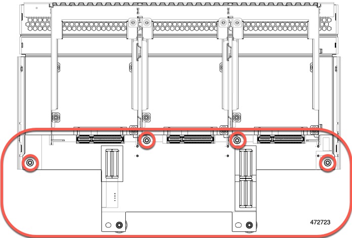
The compute node's front mezzanine module contains one PCBA, which sits horizontally and connects the drive backplane to the main motherboard. The PCBA is attached to the front mezzanine module's sheetmetal by four T8 screws.

You must disconnect the PCBA from the sheetmetal before recycling the PCBA.

Before you begin


Note


For Recyclers Only! This procedure is not a standard field-service option. This procedure is for recyclers who will be reclaiming the electronics for proper disposal to comply with local eco design and e-waste regulations.


To remove the printed circuit board assembly (PCBA), the following requirements must be met:

Gather the following tools:

  • A T8 Torx screwdriver

  • A #2 Phillips screwdriver

Procedure


Step 1

Remove the front mezzanine module from the compute node.

  1. Go to Removing the Front Mezzanine Module.

  2. Place the front mezzanine module upside down on a rubberized mat or other ESD-safe work surface.

Step 2

Disconnect the drive backplane.

  1. Using a #2 Phillips screwdriver, remove the two screws on the drive backplane.

  2. Grasp the drive backplane and lift it off of the sheetmetal frame.

Step 3

Disconnect the PCBA from the sheetmetal frame.

  1. Locate the PCBA and use a T8 Torx screwdriver to remove the four screws that secure the PCBA to the sheetmetal frame.

  2. Grasp the PCBA and detach it from the front mezzanine module.

Step 4

Dispose of the PCBA properly in accordance with your local recycling and e-waste laws.