Routing Basics and Static Routes

The system uses a routing table to determine the egress interface for packets entering the system. The following topics explain routing basics and how to configure static routing on the device.

Best Practices for Routing

Designing the routing processes in a network can be a complex process. This chapter assumes that you are configuring the Firepower Threat Defense device to work within an existing network and to participate in the routing processes that you have already established in the network.

If you are instead creating a new network, please take the time to read elsewhere about routing protocols and how to design an effective routing plan that works for your network. This chapter does not go into recommendations for choosing protocols, nor does it go into depth on how the protocols work.

If your network is very small, and you are simply linking up to an ISP, you might need nothing more than a few static routes, and not need to implement routing protocols at all.

But if you are setting up a large network that will include many routers, you probably need to implement at least one routing protocol for interior routing, such as OSPF, and possibly one for external routing, such as BGP. Your service provider can help you understand what external routing might be needed, if any. If this is your situation, first understand which routing protocols you can configure using Firepower Threat Defense, then plan your network, and finally configure the Firepower Threat Defense device according to your plan.

Routing Overview

The following topics describe how routing behaves within the Firepower Threat Defense device. Routing is the act of moving information across a network from a source to a destination. Along the way, at least one intermediate node is typically encountered. Routing involves two basic activities: determining optimal routing paths and transporting packets through a network.

Supported Routing Protocols

The following table explains the routing protocols and technologies you can configure on a FTD device using the FDM, and the method you need to use to complete the configuration.

Table 1. Supported Routing Protocols

Routing Feature

Configuration Method

Notes

BGP

Smart CLI

Configure BGP Smart CLI objects from the Device > Routing page.

Configure objects used in BGP, such as route maps, using Smart CLI objects from the Device > Advanced Configuration page.

Bi-directional forwarding detection (BFD)

FlexConfig

Configure BFD using FlexConfig objects from the Device > Advanced Configuration page. BFD is supported with BGP only.

EIGRP

Smart CLI

Configure EIGRP Smart CLI objects from the Device > Routing page.

Configure objects used in EIGRP, such as route maps, using Smart CLI objects from the Device > Advanced Configuration page.

IS-IS

FlexConfig

Configure IS-IS using FlexConfig objects from the Device > Advanced Configuration page.

Multicast routing

FlexConfig

Configure multicast routing using FlexConfig objects from the Device > Advanced Configuration page.

OSPFv2

Smart CLI

Configure OSPFv2 Smart CLI objects from the Device > Routing page.

Configure objects used in OSPFv2, such as route maps, using Smart CLI objects from the Device > Advanced Configuration page.

OSPFv3

OSPFv3 configuration is not supported.

Policy-based routing (PBR)

FlexConfig

Configure policy-based routing (PBR) using FlexConfig objects from the Device > Advanced Configuration page.

RIP

FlexConfig

Configure RIP using FlexConfig objects from the Device > Advanced Configuration page.

Static routes

FDM

Configure static routes globally or per virtual router from the Device > Routing page.

Virtual routers, VRF

FDM

Configure virtual routers from the Device > Routing page.

Route Types

There are two main types of route: static or dynamic.

Static routes are those that you define explicitly. These are stable, normally high-priority routes, that you would use to ensure traffic to the route destination is always sent out the correct interface. For example, you would create a default static route to cover all traffic not already covered by any other route, that is, 0.0.0.0/0 for IPv4 or ::/0 for IPv6. Another example would be a static route to an internal syslog server that you always want to use.

Dynamic routes are those learned through the operation of a routing protocol, such as OSPF, BGP, EIGRP, IS-IS, or RIP. You do not define the routes directly. Instead, you configure the routing protocol, and the system then communicates with neighbor routers, transmitting routing updates to them and receiving routing updates in turn.

Dynamic routing protocols adjust the routing table to changing network circumstances by analyzing incoming routing update messages. If the message indicates that a network change has occurred, the system recalculates routes and sends out new routing update messages. These messages permeate the network, stimulating routers to rerun their algorithms and change their routing tables accordingly.

Static routing is simple and serves the purpose of basic routing. It works well in environments where network traffic is relatively predictable and where network design is relatively simple. However, because static routes cannot change unless you edit them, they cannot react to changes in the network.

Unless you have a small network, you would typically combine static routes with one or more dynamic routing protocol. You would define at least one static route, as the default route for any traffic that does not match an explicit route.


Note


You can use Smart CLI to configure the following routing protocols: OSPF, BGP. Use FlexConfig to configure other routing protocols that are supported in ASA software.


The Routing Table and Route Selection

When NAT translations (xlates) and rules do not determine the egress interface, the system uses the routing table to determine the path for a packet.

Routes in the routing table include a metric called “administrative distance” that provides a relative priority to a given route. If a packet matches more than one route entry, the one with the lowest distance is used. Directly connected networks (those defined on an interface) have the distance 0, so they are always preferred. Static routes have a default distance of 1, but you can create them with any distance between 1-254.

Routes that identify a specific destination take precedence over the default route (the route whose destination is 0.0.0.0/0 or ::/0).

How the Routing Table Is Populated

The FTD routing table can be populated by statically defined routes, directly connected routes, and routes discovered by the dynamic routing protocols. Because the FTD device can run multiple routing protocols in addition to having static and connected routes in the routing table, it is possible that the same route is discovered or entered in more than one manner. When two routes to the same destination are put into the routing table, the one that remains in the routing table is determined as follows:

  • If the two routes have different network prefix lengths (network masks), then both routes are considered unique and are entered into the routing table. The packet forwarding logic then determines which of the two to use.

    For example, if the RIP and OSPF processes discovered the following routes:

    • RIP: 192.168.32.0/24

    • OSPF: 192.168.32.0/19

    Even though OSPF routes have the better administrative distance, both routes are installed in the routing table because each of these routes has a different prefix length (subnet mask). They are considered different destinations and the packet forwarding logic determines which route to use.

  • If the FTD device learns about multiple paths to the same destination from a single routing protocol, such as RIP, the route with the better metric (as determined by the routing protocol) is entered into the routing table.

    Metrics are values associated with specific routes, ranking them from most preferred to least preferred. The parameters used to determine the metrics differ for different routing protocols. The path with the lowest metric is selected as the optimal path and installed in the routing table. If there are multiple paths to the same destination with equal metrics, load balancing is done on these equal cost paths.

  • If the FTD device learns about a destination from more than one routing protocol, the administrative distances of the routes are compared, and the routes with lower administrative distance are entered into the routing table.

Administrative Distances for Routes

You can change the administrative distances for routes discovered by or redistributed into a routing protocol. If two routes from two different routing protocols have the same administrative distance, then the route with the lower default administrative distance is entered into the routing table. In the case of EIGRP and OSPF routes, if the EIGRP route and the OSPF route have the same administrative distance, then the EIGRP route is chosen by default.

Administrative distance is a route parameter that the FTD device uses to select the best path when there are two or more different routes to the same destination from two different routing protocols. Because the routing protocols have metrics based on algorithms that are different from the other protocols, it is not always possible to determine the best path for two routes to the same destination that were generated by different routing protocols.

Each routing protocol is prioritized using an administrative distance value. The following table shows the default administrative distance values for the routing protocols supported by the FTD device.

Table 2. Default Administrative Distance for Supported Routing Protocols

Route Source

Default Administrative Distance

Connected interface

0

VPN route

1

Static route

1

EIGRP Summary Route

5

External BGP

20

Internal EIGRP

90

OSPF

110

IS-IS

115

RIP

120

EIGRP external route

170

Internal and local BGP

200

Unknown

255

The smaller the administrative distance value, the more preference is given to the protocol. For example, if the FTD device receives a route to a certain network from both an OSPF routing process (default administrative distance - 110) and a RIP routing process (default administrative distance - 120), the FTD device chooses the OSPF route because OSPF has a higher preference. In this case, the router adds the OSPF version of the route to the routing table.

A VPN advertised route (V-Route/RRI)) is equivalent to a static route with the default administrative distance 1. But it has a higher preference as with the network mask 255.255.255.255.

In this example, if the source of the OSPF-derived route was lost (for example, due to a power shutdown), the FTD device would then use the RIP-derived route until the OSPF-derived route reappears.

The administrative distance is a local setting. For example, if you change the administrative distance of routes obtained through OSPF, that change would only affect the routing table for the FTD device on which the command was entered. The administrative distance is not advertised in routing updates.

Administrative distance does not affect the routing process. The routing processes only advertise the routes that have been discovered by the routing process or redistributed into the routing process. For example, the RIP routing process advertises RIP routes, even if routes discovered by the OSPF routing process are used in the routing table.

Backup Dynamic and Floating Static Routes

A backup route is registered when the initial attempt to install the route in the routing table fails because another route was installed instead. If the route that was installed in the routing table fails, the routing table maintenance process calls each routing protocol process that has registered a backup route and requests them to reinstall the route in the routing table. If there are multiple protocols with registered backup routes for the failed route, the preferred route is chosen based on administrative distance.

Because of this process, you can create floating static routes that are installed in the routing table when the route discovered by a dynamic routing protocol fails. A floating static route is simply a static route configured with a greater administrative distance than the dynamic routing protocols running on the FTD device. When the corresponding route discovered by a dynamic routing process fails, the static route is installed in the routing table.

How Forwarding Decisions Are Made

Forwarding decisions are made as follows:

  • If the destination does not match an entry in the routing table, the packet is forwarded through the interface specified for the default route. If a default route has not been configured, the packet is discarded.

  • If the destination matches a single entry in the routing table, the packet is forwarded through the interface associated with that route.

  • If the destination matches more than one entry in the routing table, then the packet is forwarded out of the interface associated with the route that has the longer network prefix length.

For example, a packet destined for 192.168.32.1 arrives on an interface with the following routes in the routing table:

  • 192.168.32.0/24 gateway 10.1.1.2

  • 192.168.32.0/19 gateway 10.1.1.3

In this case, a packet destined to 192.168.32.1 is directed toward 10.1.1.2, because 192.168.32.1 falls within the 192.168.32.0/24 network. It also falls within the other route in the routing table, but 192.168.32.0/24 has the longest prefix within the routing table (24 bits verses 19 bits). Longer prefixes are always preferred over shorter ones when forwarding a packet.


Note


Existing connections continue to use their established interfaces even if a new similar connection would result in different behavior due to a change in routes.


Routing Table for Management Traffic

As a standard security practice, it is often necessary to segregate and isolate management (from-the-device) traffic from data traffic. To achieve this isolation, the FTD device uses a separate routing table for management-only traffic vs. data traffic. Separate routing tables means that you can create separate default routes for data and management as well.

Types of Traffic for Each Routing Table

Through-the-device traffic always uses the data routing table.

From-the-device traffic, depending on the type, uses either the management-only routing table or the data routing table by default. If a match is not found in the default routing table, it checks the other routing table.

  • Management-only table from-the-device traffic includes AAA server communications.

  • Data table from-the-device traffic includes DNS server lookups and DDNS. An exception is if you only specify the Diagnostic interface for DNS, then the FTD device will only use the management-only table.

Interfaces Included in the Management-Only Routing Table

Management-only interfaces include any the Management x/x interfaces as well as any interfaces that you have configured to be management-only.


Note


The Management virtual interface uses its own Linux routing table that is not part of the FTD route lookup. Traffic originating on the Management interface includes the FDM management sessions, licensing communication, and database updates. The Diagnostic logical interface, on the other hand, uses the management-only routing table described in this section.


Fallback to the Other Routing Table

If a match is not found in the default routing table, it checks the other routing table.

Using the Non-Default Routing Table

If you need from-the-box traffic to go out an interface that isn't in its default routing table, then you might need to specify that interface when you configure it, rather than relying on the fall back to the other table. The FTD will only check routes for the specified interface. For example, if you need to communicate with a RADIUS server on a data interface, then specify that interface in the RADIUS configuration. Otherwise, if there is a default route in the management-only routing table, then it will match the default route and never fall back to the data routing table.

Equal-Cost Multi-Path (ECMP) Routing

The FTD device supports Equal-Cost Multi-Path (ECMP) routing.

You can have up to 8 equal cost static or dynamic routes per interface. For example, you can configure multiple default routes on the outside interface that specify different gateways.


route for 0.0.0.0 0.0.0.0 through outside to 10.1.1.2
route for 0.0.0.0 0.0.0.0 through outside to 10.1.1.3
route for 0.0.0.0 0.0.0.0 through outside to 10.1.1.4

In this case, traffic is load-balanced on the outside interface between 10.1.1.2, 10.1.1.3, and 10.1.1.4. Traffic is distributed among the specified gateways based on an algorithm that hashes the source and destination IP addresses, incoming interface, protocol, source and destination ports.

ECMP Across Multiple Interfaces Using Traffic Zones

If you configure traffic zones to contain a group of interfaces, you can have up to 8 equal cost static or dynamic routes across up to 8 interfaces within each zone. For example, you can configure multiple default routes across three interfaces in the zone:


route for 0.0.0.0 0.0.0.0 through outside1 to 10.1.1.2
route for 0.0.0.0 0.0.0.0 through outside2 to 10.2.1.2
route for 0.0.0.0 0.0.0.0 through outside3 to 10.3.1.2

Similarly, your dynamic routing protocol can automatically configure equal cost routes. The FTD device load-balances traffic across the interfaces with a more robust load balancing mechanism.

When a route is lost, the device seamlessly moves the flow to a different route.

Static Routes

You can create static routes to provide basic routing for your network.

About Static and Default Routes

To route traffic to a non-connected host or network, you must define a route to the host or network, either using static or dynamic routing. Generally, you must configure at least one static route: a default route for all traffic that is not routed by other means to a default network gateway, typically the next hop router.

Default Route

The simplest option is to configure a default static route to send all traffic to an upstream router, relying on the router to route the traffic for you. A default route identifies the gateway IP address to which the FTD device sends all IP packets for which it does not have a learned or static route. A default static route is simply a static route with 0.0.0.0/0 (IPv4) or ::/0 (IPv6) as the destination IP address.

You should always define a default route.

Because the FTD device uses separate routing tables for data traffic and for management traffic, you can optionally configure a default route for data traffic and another default route for management traffic. Note that from-the-device traffic uses either the management-only or data routing table by default depending on the type, but will fall back to the other routing table if a route is not found. Default routes will always match traffic, and will prevent a fall back to the other routing table. In this case, you must specify the interface you want to use for egress traffic if that interface is not in the default routing table. The Diagnostic interface is included in the management-only table. The special Management interface uses a separate Linux routing table, and has its own default route.

Static Routes

You might want to use static routes in the following cases:

  • Your networks use an unsupported router discovery protocol.

  • Your network is small and you can easily manage static routes.

  • You do not want the traffic or CPU overhead associated with routing protocols.

  • In some cases, a default route is not enough. The default gateway might not be able to reach the destination network, so you must also configure more specific static routes. For example, if the default gateway is outside, then the default route cannot direct traffic to any inside networks that are not directly connected to the FTD device.

  • You are using a feature that does not support dynamic routing protocols.

Backup Static Routes and Static Route Tracking

One of the problems with static routes is that there is no inherent mechanism for determining if the route is up or down. Static routes remain in the routing table even if the next hop gateway becomes unavailable. Static routes are only removed from the routing table if the associated interface goes down.

By implementing route tracking, using a Service Level Agreement (SLA) monitor, you can track the availability of a static route and automatically install a backup route if the primary route should fail. For example, you can define a default route to an ISP gateway and a backup default route to a secondary ISP in case the primary ISP becomes unavailable.

When you use route tracking, you associate a target IP address on the destination network to the tracked route. The system then uses ICMP echo requests to periodically verify that the address can be reached. If the system does not receive an echo reply within the time period you specify, the host is considered unreachable, and the system removes the associated route from the routing table. The system can then use an untracked backup route with a higher metric in place of the removed route.

Thus, to use a backup static route for a given destination, including for a default route, you must do the following:

  1. Create an SLA monitor that will monitor a reliable IP address on the destination network, such as a gateway or an always-up server (such as a web server or syslog server). Do not monitor the IP address of a system that might be taken off-line while the destination network remains healthy and available. See Configure SLA Monitor Objects.

  2. Create the primary route to the destination and select the SLA monitor for the route. The metric for this route should typically be 1. See Configuring Static Routes.

  3. Create the backup static route that will be used if the primary route fails. This route must have a larger metric than the primary route. For example, if the primary route is 1, the backup route could be 10. You would also normally select a different interface for the backup route.

Guidelines for Static Routing

Bridge Groups

  • In routed mode, you must specify the BVI as the gateway; you cannot specify the member interface.

  • For traffic that originates on the FTD device (such as syslog or SNMP) that is destined through a bridge group member interface for a non-directly connected network, you need to configure either a default route or static routes so the FTD device knows out of which bridge group member interface to send traffic. If you have servers that cannot all be reached through a single default route, then you must configure static routes.

  • Static route tracking is not supported for bridge group member interfaces or on the BVI.

IPv6

  • Static route tracking (SLA monitor) is not supported for IPv6.

Equal-Cost Multi-Path (ECMP) Traffic Zones

  • Keep the member interfaces of a ECMP traffic zone in the same security zone to prevent different access, SSL, or identity rules being applied to those interfaces.

  • You can have up to 8 equal-cost routes for a network in a given ECMP traffic zone.

  • You can create up to 256 ECMP traffic zones, with up to 8 interfaces per zone.

  • ECMP traffic zones can contain named physical interfaces, subinterfaces, and Etherchannels. They cannot contain the following:

    • A bridge group (BVI) or its members

    • Etherchannel member interfaces

    • HA interfaces (failover or state links)

    • Management-only interfaces

    • Interfaces used for site-to-site VPN or remote access VPN connections.

    • Virtual tunnel interfaces (VTI) or their source interfaces.

    • Interfaces configured for VPN management access.

  • You cannot enable DHCP Relay on an interface in a zone.

Configuring Static Routes

Define static routes to tell the system where to send packets that are not bound for networks that are directly connected to the interfaces on the system.

You need at least one static route, the default route, for network 0.0.0.0/0. This route defines where to send packets whose egress interface cannot be determined by existing NAT xlates (translations) or static NAT rules, or other static routes.

You might need other static routes if the default gateway cannot be used to get to all networks. For example, the default route is usually an upstream router on the outside interface. If there are additional inside networks that are not directly connected to the device, and they cannot be accessed through the default gateway, you need static routes for each of those inside networks.

You cannot define static routes for the networks that are directly connected to system interfaces. The system automatically creates these routes.

Procedure


Step 1

Click Device, then click the link in the Routing summary.

Step 2

If you enabled virtual routers, click the view icon (View configuration button.) for the router in which you are configuring a static route.

Step 3

On the Static Routing page, do one of the following:

  • To add a new route, click +.
  • Click the edit icon () for the route you want to edit.

If you no longer need a route, click the trash can icon for the route to delete it.

Step 4

Configure the route properties

  • Name—A display name for the route.

  • Description—An optional description of the purpose for the route.

  • Interface—Select the interface through which you want to send traffic. The gateway address needs to be accessible through this interface.

    For bridge groups, you configure the route for the bridge group interface (BVI), not for the member interfaces.

    If you have enabled virtual routing and forwarding, you can select an interface that belongs to a different virtual router. If you create a static route in a virtual router for an interface in a different virtual router, the route will cross virtual router boundaries, with the risk that traffic from this virtual router will leak into another virtual router. This might be the desired result, but carefully determine that you need this route leak. As you select interfaces, the name of the virtual router to which the interface belongs will be shown to the right of the interface.

  • Protocol—Select whether the route is for an IPv4 or IPv6 address.

  • Networks—Select the network objects that identify the destination networks or hosts that should use the gateway in this route.

    To define a default route, use the pre-defined any-ipv4 or any-ipv6 network objects, or create an object for the 0.0.0.0/0 (IPv4) or ::/0 (IPv6) network.

  • Gateway—Select the host network object that identifies the IP address for the gateway. Traffic is sent to this address. You cannot use the same gateway for routes on more than one interface.

    If you are defining a route in a virtual router, and the interface belongs to a different virtual router, you must leave the gateway empty. The system will route traffic to these networks to the other virtual router, and then use the target virtual router's routing table to determine the gateway.

  • Metric—The administrative distance for the route, between 1 and 254. The default for static routes is 1. If there are additional routers between the interface and the gateway, enter the number of hops as the administrative distance.

    Administrative distance is a parameter used to compare routes. The lower the number, the higher precedence the route is given. Connected routes (networks directly connected to an interface on the device) always take precedence over static routes.

Step 5

(Optional; IPv4 routes only.) Select the SLA Monitor that should track this route's viability.

An SLA Monitor can verify that an always-available host on the target network is reachable. If it becomes unreachable, the system can install a backup route. Thus, if you configure an SLA Monitor, you should also configure another static route, with a larger metric, for this network. For example, if this route has the metric 1, create a backup route with the metric 10. For more information, see Backup Static Routes and Static Route Tracking.

If the SLA Monitor object does not yet exist, click the Create SLA Monitor link at the bottom of the list and create it now.

Note


If a monitored route is removed because the monitored address cannot be pinged, the route is indicated in the static route table with a warning that the route is unreachable. Determine if the problem is temporary or if you need to reconfigure the route. Consider the possibility that the route is viable but that the monitored address is not sufficiently dependable.

Step 6

Click OK.


Configure SLA Monitor Objects

Configure Service Level Agreement (SLA) Monitor objects for use with static routes. By using an SLA monitor, you can track the health of a static route and automatically replace a failed route with a new one. For more information on route tracking, see Backup Static Routes and Static Route Tracking.

When selecting a monitoring target, you need to make sure that it can respond to ICMP echo requests. The target can be any IP address, defined in a host network object, but you should consider using the following:

  • The ISP gateway address, for dual ISP support.

  • The next hop gateway address, if you are concerned about the availability of the gateway.

  • A server on the target network, such as a syslog server, that the system needs to communicate with.

  • A persistent IP address on the destination network. A workstation that might be shut down at night is not a good choice.

Procedure

Step 1

Select Objects, then select SLA Monitors from the table of contents.

Step 2

Do one of the following:

  • To create an object, click the + button.

  • To edit an object, click the edit icon (edit icon) for the object.

To delete an unreferenced object, click the trash can icon (delete icon) for the object.

Step 3

Enter a Name for the object and optionally, a description.

Step 4

Define the SLA monitor required options:

  • Monitor Address—Select the host network object that defines the address to be monitored on the destination network. You can click Create New Network if the object you require does not exist.

    This address is monitored only if you attach the SLA monitor to a static route.

  • Target Interface—Select the interface through which to send the echo request packets. This is normally the interface on which you will define the static route. The interface source address is used as the source address in the echo request packets.

Step 5

(Optional.) Adjust the IP ICMP Echo Options.

All of the ICMP options have defaults that are appropriate in most cases, but you can tune them to fit your requirements.

  • Threshold—The number of milliseconds for a rising threshold to be declared, from 0 to 2147483647. The default is 5000 (5 seconds). This value should not be larger than the value set for the timeout. The threshold value is only used to indicate over threshold events, which do not affect reachability. You can use the frequency of threshold events to evaluate the setting for timeout.

  • Timeout—The amount of time, in milliseconds, that the route monitoring operation should wait for a response from the request packets, from 0 to 604800000 milliseconds (7 days). The default value is 5000 milliseconds (5 seconds). If the monitor does not get a response to at least one echo request during this period, the process installs the backup route.

  • Frequency—The number of milliseconds between SLA probes, from 1000 to 604800000, in multiples of 1000. You cannot set a frequency that is less than the timeout value. The default is 60000 milliseconds (60 seconds).

  • Type of Service—An integer that defines the Type of Service (ToS) type in the IP header of the ICMP echo request packet, from 0 to 255. The default is 0.

  • Number of Packets—The number of packets to be sent with each poll, from 1 to 100. The default is 1 packet.

  • Data Size—The size of the data payload to use in the echo request packets, from 0 to 16384 bytes. The default value is 28. This setting specifies the size of the payload only; it does not specify the size of the entire packet.

Step 6

Click OK.

You can now use the SLA monitor object in a static route.


Configuring ECMP Traffic Zones

Normally, to configure multiple routes for a given network prefix, using the same route metric, you need to configure the routes on the same interface. Thus, the system uses Equal-Cost Multi-Path (ECMP) routing calculations to load balance traffic sent through the interface to the gateways.

For example, you can configure multiple default routes on the outside interface that specify different gateways, and this configuration is allowed without additional changes:


route for 0.0.0.0 0.0.0.0 through outside to 10.1.1.2
route for 0.0.0.0 0.0.0.0 through outside to 10.1.1.3
route for 0.0.0.0 0.0.0.0 through outside to 10.1.1.4

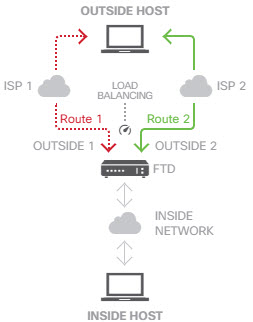
You can also use ECMP to balance traffic across multiple interfaces (within a virtual router) for the same network prefix and route metric. This configuration is necessary if the gateways are accessible through separate interfaces. For example, say you have two ISPs, and you want to load balance among the ISPs, but you do not want to divide your internal address spaces between the ISP gateways. One ISP is accessible through the outside1 interface, the other through the outside2 interface. To accomplish this, you would need to create a routing traffic zone that contains the outside1 and outside2 interfaces.


isp-zone containing outside1 and outside2
route for 0.0.0.0 0.0.0.0 through outside1 to 10.1.1.2
route for 0.0.0.0 0.0.0.0 through outside2 to 10.1.1.3

ECMP traffic zone use.


Note


An ECMP routing traffic zone is not related to security zones. Creating a security zone that contains the outside1 and outside2 interfaces does not implement a traffic zone for ECMP routing purposes.


The following procedure explains how to configure ECMP zones to take advantage of ECMP processing across interfaces.

Procedure


Step 1

Click Device, then click the link in the Routing summary.

Step 2

If you enabled virtual routers, click the view icon (View configuration button.) for the router in which you are configuring a static route.

Step 3

Click the ECMP Traffic Zones tab.

Step 4

On the ECMP Traffic Zones page, do one of the following:

  • To add a new zone, click +, or Add ECMP Traffic Zone.
  • Click the edit icon () for the zone you want to edit.

If you no longer need a zone, click the trash can icon for the zone to delete it. You must remove any static routes that depend on a zone before you can delete the zone.

Step 5

Enter a Name for the zone and optionally, a description.

Step 6

Select up to 8 Interfaces to include in the zone:

  • Click + to add an interface.

  • Click x to the right of an interface to remove it.

While selecting interfaces, keep the following restrictions in mind:

  • You can select physical interfaces, subinterfaces, and Etherchannels.

  • An ECMP traffic zone cannot include the following types of interface: a bridge group (BVI) or its members, Etherchannel member interfaces, HA interfaces (failover or state links), management-only interfaces, virtual tunnel interfaces (VTI), or interfaces configured for VPN management access.

  • You cannot include interfaces that are used in remote access or site-to-site VPN connections.

  • You cannot select interfaces that are enabled for DHCP relay, either as server or agent.

  • The interfaces must be assigned to the same virtual router.

  • An interface can be in one traffic zone only.

Step 7

Click OK.


What to do next

You can now go to the Static Routes tab and create equal-cost routes through these interfaces for the same destination. Alternately, your dynamic routing protocols can automatically configure equal-cost routes if they are distributed through the system.

Monitoring Routing

To monitor and troubleshoot routing, open the CLI console or log into the device CLI and use the following commands. You can also select some of these commands from the Commands menu on the Routing page.

  • show route displays the routing table for the data interfaces, including routes for directly-connected networks.

  • show ipv6 route displays the IPv6 routing table for the data interfaces, including routes for directly-connected networks.

  • show network displays the configuration for the virtual Management interface, including the management gateway. Routing through the virtual Management interface is not handled by the data interface routing table, unless you specify data-interfaces as the management gateway.

  • show network-static-routes displays static routes configured for the virtual Management interface using the configure network static-routes command. Normally, there will not be any static routes, as the management gateway suffices for management routing in most cases. These routes are not available to traffic on the data interfaces. This command is not available in the CLI console.

  • show ospf displays information about the OSPF processes and learned routes. Use show ospf ? to get a list of options you can include to view specific information about OSPF.

  • show bgp displays information about the BGP processes and learned routes. Useshow bgp ? to get a list of options you can include to view specific information about BGP.

  • show eigrp option displays information about the EIGRP processes and learned routes. Use show eigrp ? to get a list of options you can include; you must supply an option.

  • show isis option displays information about the IS-IS processes and learned routes. Use show isis ? to get a list of options you can include; you must supply an option.

  • show rip database displays information about the RIP processes and learned routes.

  • show vrf displays information about the virtual routers defined on the system.

  • show zone displays information about ECMP traffic zones, including the interfaces that are part of each zone.