Routed and Transparent Mode Interfaces

This chapter includes tasks to complete the interface configuration for all models in routed or transparent firewall mode.


Note

For multiple context mode, complete the tasks in this section in the context execution space. In the Configuration > Device List pane, double-click the context name under the active device IP address.


About Routed and Transparent Mode Interfaces

The ASA supports two types of interfaces: routed and bridged.

Each Layer 3 routed interface requires an IP address on a unique subnet.

Bridged interfaces belong to a bridge group, and all interfaces are on the same network. The bridge group is represented by a Bridge Virtual Interface (BVI) that has an IP address on the bridge network. Routed mode supports both routed and bridged interfaces, and you can route between routed interfaces and BVIs. Transparent firewall mode only supports bridge group and BVI interfaces.

Security Levels

Each interface must have a security level from 0 (lowest) to 100 (highest), including bridge group member interfaces. For example, you should assign your most secure network, such as the inside host network, to level 100. While the outside network connected to the Internet can be level 0. Other networks, such as DMZs can be in between. You can assign interfaces to the same security level.

Whether you assign a security level to a BVI depends on the firewall mode. In transparent mode, the BVI interface does not have a security level because it does not participate in routing between interfaces. In routed mode, BVI interfaces have a security level if you choose to route between the BVIs and other interfaces. For routed mode, the security level on a bridge group member interface only applies for communication within the bridge group. Similarly, the BVI security level only applies for inter-BVI/Layer 3 interface communication.

The level controls the following behavior:

  • Network access—By default, there is an implicit permit from a higher security interface to a lower security interface (outbound). Hosts on the higher security interface can access any host on a lower security interface. You can limit access by applying an ACL to the interface.

    If you enable communication for same-security interfaces, there is an implicit permit for interfaces to access other interfaces on the same security level or lower.

  • Inspection engines—Some application inspection engines are dependent on the security level. For same-security interfaces, inspection engines apply to traffic in either direction.

    • NetBIOS inspection engine—Applied only for outbound connections.

    • SQL*Net inspection engine—If a control connection for the SQL*Net (formerly OraServ) port exists between a pair of hosts, then only an inbound data connection is permitted through the ASA.

Dual IP Stack (IPv4 and IPv6)

The ASA supports both IPv6 and IPv4 addresses on an interface. Make sure you configure a default route for both IPv4 and IPv6.

31-Bit Subnet Mask

For routed interfaces, you can configure an IP address on a 31-bit subnet for point-to-point connections. The 31-bit subnet includes only 2 addresses; normally, the first and last address in the subnet is reserved for the network and broadcast, so a 2-address subnet is not usable. However, if you have a point-to-point connection and do not need network or broadcast addresses, a 31-bit subnet is a useful way to preserve addresses in IPv4. For example, the failover link between 2 ASAs only requires 2 addresses; any packet that is transmitted by one end of the link is always received by the other, and broadcasting is unnecessary. You can also have a directly-connected management station running SNMP or Syslog.

31-Bit Subnet and Clustering

You can use a 31-bit subnet mask in Spanned clustering mode, excluding the management interface and the Cluster Control Link.

You cannot use a 31-bit subnet mask in Individual clustering mode on any interface.

31-Bit Subnet and Failover

For failover, when you use a 31-bit subnet for the ASA interface IP address, you cannot configure a standby IP address for the interface because there are not enough addresses. Normally, an interface for failover should have a standby IP address so the active unit can perform interface tests to ensure standby interface health. Without a standby IP address, the ASA cannot perform any network tests; only the link state can be tracked.

For the failover and optional separate state link, which are point-to-point connections, you can also use a 31-bit subnet.

31-Bit Subnet and Management

If you have a directly-connected management station, you can use a point-to-point connection for SSH or HTTP on the ASA, or for SNMP or Syslog on the management station.

31-Bit Subnet Unsupported Features

The following features do not support the 31-Bit subnet:

  • BVI interfaces for bridge groups—The bridge group requires at least 3 host addresses: the BVI, and two hosts connected to two bridge group member interfaces. you must use a /29 subnet or smaller.

  • Multicast Routing

Guidelines and Limitations for Routed and Transparent Mode Interfaces

Context Mode

  • In multiple context mode, you can only configure context interfaces that you already assigned to the context in the system configuration according to Configure Multiple Contexts.

  • PPPoE is not supported in multiple context mode.

  • For multiple context mode in transparent mode, each context must use different interfaces; you cannot share an interface across contexts.

  • For multiple context mode in transparent mode, each context typically uses a different subnet. You can use overlapping subnets, but your network topology requires router and NAT configuration to make it possible from a routing standpoint.

  • DHCPv6 and prefix delegation options are not supported with multiple context mode.

  • In routed firewall mode, bridge group interfaces are not supported in multiple context mode.

Failover, Clustering

  • Do not configure failover links with the procedures in this chapter. See the Failover chapter for more information.

  • For cluster interfaces, see the clustering chapter for requirements.

  • When you use Failover, you must set the IP address and standby address for data interfaces manually; DHCP and PPPoE are not supported.

IPv6

  • IPv6 is supported on all interfaces.

  • You can only configure IPv6 addresses manually in transparent mode.

  • The ASA does not support IPv6 anycast addresses.

  • DHCPv6 and prefix delegation options are not supported with multiple context mode, transparent mode, clustering, or Failover.

Model Guidelines

  • For the ASAv50, bridge groups are not supported in either transparent or routed mode.

  • For the Firepower 2100 series, bridge groups are not supported in routed mode.

Transparent Mode and Bridge Group Guidelines

  • You can create up to 250 bridge groups, with 64 interfaces per bridge group.

  • Each directly-connected network must be on the same subnet.

  • The ASA does not support traffic on secondary networks; only traffic on the same network as the BVI IP address is supported.

  • An IP address for the BVI is required for each bridge group for to-the-device and from-the-device management traffic, as well as for data traffic to pass through the ASA. For IPv4 traffic, specify an IPv4 address. For IPv6 traffic, specify an IPv6 address.

  • You can only configure IPv6 addresses manually.

  • The BVI IP address must be on the same subnet as the connected network. You cannot set the subnet to a host subnet (255.255.255.255).

  • Management interfaces are not supported as bridge group members.

  • For the ASAv50 on VMware with bridged ixgbevf interfaces, transparent mode is not supported, and bridge groups are not supported in routed mode.

  • For the Firepower 2100 series, bridge groups are not supported in routed mode.

  • For the Firepower 1010, you cannot mix logical VLAN interfaces and physical firewall interfaces in the same bridge group.

  • In transparent mode, you must use at least 1 bridge group; data interfaces must belong to a bridge group.

  • In transparent mode, do not specify the BVI IP address as the default gateway for connected devices; devices need to specify the router on the other side of the ASA as the default gateway.

  • In transparent mode, the default route, which is required to provide a return path for management traffic, is only applied to management traffic from one bridge group network. This is because the default route specifies an interface in the bridge group as well as the router IP address on the bridge group network, and you can only define one default route. If you have management traffic from more than one bridge group network, you need to specify a regular static route that identifies the network from which you expect management traffic.

  • In transparent mode, PPPoE is not supported for the Management interface.

  • In routed mode, to route between bridge groups and other routed interfaces, you must name the BVI.

  • In routed mode, ASA-defined EtherChannel and VNI interfaces are not supported as bridge group members. EtherChannels on the Firepower 4100/9300 can be bridge group members.

  • Bidirectional Forwarding Detection (BFD) echo packets are not allowed through the ASA when using bridge group members. If there are two neighbors on either side of the ASA running BFD, then the ASA will drop BFD echo packets because they have the same source and destination IP address and appear to be part of a LAND attack.

Default Security Level

The default security level is 0. If you name an interface “inside,” and you do not set the security level explicitly, then the ASA sets the security level to 100.


Note

If you change the security level of an interface, and you do not want to wait for existing connections to time out before the new security information is used, you can clear the connections using the clear conn command.


Additional Guidelines and Requirements

  • The ASA supports only one 802.1Q header in a packet and does not support multiple headers (known as Q-in-Q support).

Configure Routed Mode Interfaces

To configure routed mode interfaces, perform the following steps.

Configure General Routed Mode Interface Parameters

This procedure describes how to set the name, security level, IPv4 address, and other options.

Before you begin

In multiple context mode, complete this procedure in the context execution space. To change from the system to a context configuration, in the Configuration > Device List pane, double-click the context name under the active device IP address.

Procedure


Step 1

Choose Configuration > Device Setup > Interface Settings > Interfaces.

Step 2

Choose the interface row, and click Edit.

The Edit Interface dialog box appears with the General tab selected.

Note 

For the Firepower 1010, you cannot configure switch ports as routed mode interfaces.

Step 3

In the Interface Name field, enter a name up to 48 characters in length.

Step 4

In the Security level field, enter a level between 0 (lowest) and 100 (highest).

Step 5

(Optional) To set this interface as a management-only interface, check the Dedicate this interface to management-only check box.

Through traffic is not accepted on a management-only interface.

Note 

The Channel Group field is read-only and indicates if the interface is part of an EtherChannel.

Step 6

If the interface is not already enabled, check the Enable Interface check box.

Step 7

To set the IP address, use one of the following options.

Note 

For failover and clustering, you must set the IP address manually; DHCP and PPPoE are not supported.

  • To set the IP address manually, click the Use Static IP radio button and enter the IP address and mask.

    For failover, set the standby IP addresses on the Configuration > Device Management > High Availability > Failover > Interfaces tab. If you do not set the standby IP address, the active unit cannot monitor the standby interface using network tests; it can only track the link state.

    For point-to-point connections, you can specify a 31-bit subnet mask (255.255.255.254). In this case, no IP addresses are reserved for the network or broadcast addresses. You cannot set the standby IP address in this case.
  • To obtain an IP address from a DHCP server, click the Obtain Address via DHCP radio button.

    1. To force a MAC address to be stored inside a DHCP request packet for option 61, click the Use MAC Address radio button.

      Some ISPs expect option 61 to be the interface MAC address. If the MAC address is not included in the DHCP request packet, then an IP address will not be assigned.

    2. To use a generated string for option 61, click Use “Cisco-<MAC>-<interface_name>-<host>”.

    3. (Optional) To obtain the default route from the DHCP server, check Obtain Default Route Using DHCP.

    4. (Optional) To assign an administrative distance to the learned route, enter a value between 1 and 255 in the DHCP Learned Route Metric field. If this field is left blank, the administrative distance for the learned routes is 1.

    5. (Optional) To enable tracking for DHCP-learned routes, check Enable Tracking for DHCP Learned Routes. Set the following values:

      Track ID—A unique identifier for the route tracking process. Valid values are from 1 to 500.

      Track IP Address—Enter the IP address of the target being tracked. Typically, this would be the IP address of the next hop gateway for the route, but it could be any network object available off of that interface.

      Note 

      Route tracking is only available in single, routed mode.

      SLA ID—A unique identifier for the SLA monitoring process. Valid values are from 1 to 2147483647.

      Monitor Options—Click this button to open the Route Monitoring Options dialog box. In the Route Monitoring Options dialog box you can configure the parameters of the tracked object monitoring process.

    6. (Optional) To set the broadcast flag to 1 in the DHCP packet header when the DHCP client sends a discover requesting an IP address, check Enable DHCP Broadcast flag for DHCP request and discover messages.

      The DHCP server listens to this broadcast flag and broadcasts the reply packet if the flag is set to 1.

    7. (Optional) To renew the lease, click Renew DHCP Lease.

  • (Single mode only) To obtain an IP address using PPPoE, check Use PPPoE.

    1. In the Group Name field, specify a group name.

    2. In the PPPoE Username field, specify the username provided by your ISP.

    3. In the PPPoE Password field, specify the password provided by your ISP.

    4. In the Confirm Password field, retype the password.

    5. For PPP authentication, click either the PAP, CHAP, or MSCHAP radio button.

      PAP passes cleartext username and password during authentication and is not secure. With CHAP, the client returns the encrypted [challenge plus password], with a cleartext username in response to the server challenge. CHAP is more secure than PAP, but it does not encrypt data. MSCHAP is similar to CHAP but is more secure because the server stores and compares only encrypted passwords rather than cleartext passwords as in CHAP. MSCHAP also generates a key for data encryption by MPPE.

    6. (Optional) To store the username and password in flash memory, check the Store Username and Password in Local Flash check box.

      The ASA stores the username and password in a special location of NVRAM. If an Auto Update Server sends a clear configure command to the ASA, and the connection is then interrupted, the ASA can read the username and password from NVRAM and re-authenticate to the Access Concentrator.

    7. (Optional) To display the PPPoE IP Address and Route Settings dialog box where you can choose addressing and tracking options, click IP Address and Route Settings.

Step 8

(Optional) In the Description field, enter a description for this interface.

The description can be up to 240 characters on a single line, without carriage returns. In the case of a failover or state link, the description is fixed as “LAN Failover Interface,” “STATE Failover Interface,” or “LAN/STATE Failover Interface,” for example. You cannot edit this description. The fixed description overwrites any description you enter here if you make this interface a failover or state link.

Step 9

Click OK.


Configure PPPoE

If the interface is connected to a DSL, cable modem, or other connection to your ISP, and your ISP uses PPPoE to provide your IP address, configure the following parameters.

Procedure


Step 1

Choose Configuration  > Interfaces  > Add/Edit Interface > General, and then click PPPoE IP Address and Route Settings.

Step 2

In the IP Address area, choose one of the following:

  • Obtain IP Address using PPP—Dynamically configure the IP address.
  • Specify an IP Address—Manually configure the IP address.

Step 3

In the Route Settings Area, configure the following:

  • Obtain default route using PPPoE—Set the default routes when the PPPoE client has not yet established a connection. When using this option, you cannot have a statically defined route in the configuration.

  • PPPoE learned route metric—Assign an administrative distance to the learned route. Valid values are from 1 to 255. If this field is left blank, the administrative distance for the learned routes is 1.

  • Enable tracking—Enable route tracking for PPPoE-learned routes. Route tracking is only available in single, routed mode.

  • Primary Track—Configure the primary PPPoE route tracking.

  • Track ID—A unique identifier for the route tracking process. Valid values are from 1 to 500.

  • Track IP Address—Enter the IP address of the target being tracked. Typically, this would be the IP address of the next hop gateway for the route, but it could be any network object available off of that interface.

  • SLA ID—A unique identifier for the SLA monitoring process. Valid values are from 1 to 2147483647.

  • Monitor Options—Click this button to open the Route Monitoring Options dialog box. In the Route Monitoring Options dialog box you can configure the parameters of the tracked object monitoring process.

  • Secondary Track—Configure the secondary PPPoE route tracking.

  • Secondary Track ID—A unique identifier for the route tracking process. Valid values are from 1 to 500.

Step 4

Click OK.


Configure Bridge Group Interfaces

A bridge group is a group of interfaces that the ASA bridges instead of routes. Bridge groups are supported in both transparent and routed firewall mode. For more information about bridge groups, see About Bridge Groups.

To configure bridge groups and associated interfaces, perform these steps.

Configure the Bridge Virtual Interface (BVI)

Each bridge group requires a BVI for which you configure an IP address. The ASA uses this IP address as the source address for packets originating from the bridge group. The BVI IP address must be on the same subnet as the connected network. For IPv4 traffic, the BVI IP address is required to pass any traffic. For IPv6 traffic, you must, at a minimum, configure the link-local addresses to pass traffic, but a global management address is recommended for full functionality, including remote management and other management operations.

For routed mode, if you provide a name for the BVI, then the BVI participates in routing. Without a name, the bridge group remains isolated as in transparent firewall mode.

Some models include a bridge group and BVI in the default configuration. You can create additional bridge groups and BVIs and reassign member interfaces between the groups.


Note

For a separate management interface in transparent mode (for supported models), a non-configurable bridge group (ID 301) is automatically added to your configuration. This bridge group is not included in the bridge group limit.


Procedure


Step 1

Choose Configuration > Interfaces, and then choose Add > Bridge Group Interface.

Step 2

In the Bridge Group ID field, enter the bridge group ID between 1 and 250.

You will later assign physical interfaces to this bridge group number.

Step 3

(Routed Mode) In the Interface Name field, enter a name up to 48 characters in length.

You must name the BVI if you want to route traffic outside the bridge group members, for example, to the outside interface or to members of other bridge groups.

Step 4

(Routed Mode) In the Security level field, enter a level between 0 (lowest) and 100 (highest).

Step 5

(Transparent Mode) Set the IP address.

  1. In the IP Address field, enter the IPv4 address.

  2. In the Subnet Mask field, enter the subnet mask or choose one from the menu.

    Do not assign a host address (/32 or 255.255.255.255) to the transparent firewall. Also, do not use other subnets that contain fewer than 3 host addresses (one each for the upstream router, downstream router, and transparent firewall) such as a /30 subnet (255.255.255.252). The ASA drops all ARP packets to or from the first and last addresses in a subnet. For example, if you use a /30 subnet and assign a reserved address from that subnet to the upstream router, then the ASA drops the ARP request from the downstream router to the upstream router.

Step 6

(Routed Mode) To set the IP address, use one of the following options.

For failover and clustering, you must set the IP address manually; DHCP is not supported.

  • To set the IP address manually, click the Use Static IP radio button and enter the IP address and mask.

  • To obtain an IP address from a DHCP server, click the Obtain Address via DHCP radio button.

    1. To force a MAC address to be stored inside a DHCP request packet for option 61, click the Use MAC Address radio button.

      Some ISPs expect option 61 to be the interface MAC address. If the MAC address is not included in the DHCP request packet, then an IP address will not be assigned.

    2. To use a generated string for option 61, click Use “Cisco-<MAC>-<interface_name>-<host>”.

    3. (Optional) To obtain the default route from the DHCP server, check Obtain Default Route Using DHCP.

    4. (Optional) To set the broadcast flag to 1 in the DHCP packet header when the DHCP client sends a discover requesting an IP address, check Enable DHCP Broadcast flag for DHCP request and discover messages.

      The DHCP server listens to this broadcast flag and broadcasts the reply packet if the flag is set to 1.

    5. (Optional) To renew the lease, click Renew DHCP Lease.

Step 7

(Optional) In the Description field, enter a description for this bridge group.

Step 8

Click OK.

A Bridge Virtual Interface (BVI) is added to the interface table, along with the physical and subinterfaces.


Configure General Bridge Group Member Interface Parameters

This procedure describes how to set the name, security level, and bridge group for each bridge group member interface.

Before you begin

  • The same bridge group can include different types of interfaces: physical interfaces, VLAN subinterfaces, VNI interfaces,redundant interfaces, and EtherChannels. The Management interface is not supported. In routed mode, EtherChannels and VNIs are not supported.

  • In multiple context mode, complete this procedure in the context execution space. To change from the system to a context configuration, in the Configuration > Device List pane, double-click the context name under the active device IP address.

  • For transparent mode, do not use this procedure for Management interfaces; see Configure a Management Interface for Transparent Mode to configure the Management interface.

Procedure


Step 1

Choose Configuration > Device Setup > Interface Settings > Interfaces.

BVIs appear in the table alongside physical interfaces, subinterfaces, redundant interfaces, and EtherChannel port-channel interfaces. In multiple context mode, only interfaces that were assigned to the context in the System execution space appear in the table.

Step 2

Choose the row for a non-BVI interface, and click Edit.

The Edit Interface dialog box appears with the General tab selected.

Note 

For the Firepower 1010, you cannot configure switch ports as bridge group members.

You cannot mix logical VLAN interfaces and physical router interfaces in the same bridge group.

Note 

In routed mode, the port-channel and vni interfaces are not supported as bridge group members.

Step 3

In the Bridge Group drop-down menu, choose the bridge group to which you want to assign this interface.

Step 4

In the Interface Name field, enter a name up to 48 characters in length.

Step 5

In the Security level field, enter a level between 0 (lowest) and 100 (highest).

Step 6

If the interface is not already enabled, check the Enable Interface check box.

Note 

The Channel Group field is read-only and indicates if the interface is part of an EtherChannel.

Step 7

(Optional) If you install a module, and you want to demonstrate the module functionality on a non-production ASA, check the Forward traffic to the ASA module for inspection and reporting check box. See the module chapter or quick start guide for more information.

Step 8

(Optional) In the Description field, enter a description for this interface.

The description can be up to 240 characters on a single line, without carriage returns. In the case of a failover or state link, the description is fixed as “LAN Failover Interface,” “STATE Failover Interface,” or “LAN/STATE Failover Interface,” for example. You cannot edit this description. The fixed description overwrites any description you enter here if you make this interface a failover or state link.

Step 9

Click OK.


Configure a Management Interface for Transparent Mode

In transparent firewall mode, all interfaces must belong to a bridge group. The only exception is the Management interface (either the physical interface, a subinterface (if supported for your model), or an EtherChannel interface comprised of Management interfaces (if you have multiple Management interfaces)) which you can configure as a separate management interface; for the Firepower 4100/9300 chassis, the management interface ID depends on the mgmt-type interface that you assigned to the ASA logical device. You cannot use any other interface types as management interfaces. You can configure one management interface in single mode or per context. For more information see Management Interface for Transparent Mode.

Before you begin

  • Do not assign this interface to a bridge group; a non-configurable bridge group (ID 301) is automatically added to your configuration. This bridge group is not included in the bridge group limit.

  • For the Firepower 4100/9300 chassis, the management interface ID depends on the mgmt-type interface that you assigned to the ASA logical device.

  • In multiple context mode, you cannot share any interfaces, including the Management interface, across contexts. You must connect to a data interface.

  • In multiple context mode, complete this procedure in the context execution space. To change from the system to a context configuration, in the Configuration > Device List pane, double-click the context name under the active device IP address.

Procedure


Step 1

Choose Configuration > Device Setup > Interface Settings > Interfaces.

Step 2

Choose the row for a Management interface, subinterface, or EtherChannel port-channel interface comprised of Management interfaces, and click Edit.

The Edit Interface dialog box appears with the General tab selected.

For the Firepower 4100/9300 chassis, the management interface ID depends on the mgmt-type interface (individual or EtherChannel) that you assigned to the ASA logical device.

Step 3

In the Bridge Group drop-down menu, leave the default --None--. You cannot assign a management interface to a bridge group.

Step 4

In the Interface Name field, enter a name up to 48 characters in length.

Step 5

In the Security level field, enter a level between 0 (lowest) and 100 (highest).

Note 

The Dedicate this interface to management only check box is enabled by default and is non-configurable.

Step 6

If the interface is not already enabled, check the Enable Interface check box.

Step 7

To set the IP address, use one of the following options.

Note 

For use with failover, you must set the IP address and standby address manually; DHCP is not supported. Set the standby IP addresses on the Configuration > Device Management > High Availability > Failover > Interfaces tab.

  • To set the IP address manually, click the Use Static IP radio button and enter the IP address and mask.

  • To obtain an IP address from a DHCP server, click the Obtain Address via DHCP radio button.

    • To force a MAC address to be stored inside a DHCP request packet for option 61, click the Use MAC Address radio button.

      Some ISPs expect option 61 to be the interface MAC address. If the MAC address is not included in the DHCP request packet, then an IP address will not be assigned.

    • To use a generated string for option 61, click Use “Cisco-<MAC>-<interface_name>-<host>”.

    • (Optional) To obtain the default route from the DHCP server, check Obtain Default Route Using DHCP.

    • (Optional) To set the broadcast flag to 1 in the DHCP packet header when the DHCP client sends a discover requesting an IP address, check Enable DHCP Broadcast flag for DHCP request and discover messages.

      The DHCP server listens to this broadcast flag and broadcasts the reply packet if the flag is set to 1.

    • (Optional) To renew the lease, click Renew DHCP Lease.

Step 8

(Optional) In the Description field, enter a description for this interface.

The description can be up to 240 characters on a single line, without carriage returns.

Step 9

Click OK.


Configure IPv6 Addressing

This section describes how to configure IPv6 addressing.

About IPv6

This section includes information about IPv6.

IPv6 Addressing

You can configure two types of unicast addresses for IPv6:

  • Global—The global address is a public address that you can use on the public network. For a bridge group, this address needs to be configured for the BVI, and not per member interface. You can also configure a global IPv6 address for the management interface in transparent mode.

  • Link-local—The link-local address is a private address that you can only use on the directly-connected network. Routers do not forward packets using link-local addresses; they are only for communication on a particular physical network segment. They can be used for address configuration or for the Neighbor Discovery functions such as address resolution. In a bridge group, only member interfaces have link-local addresses; the BVI does not have a link-local address.

At a minimum, you need to configure a link-local address for IPv6 to operate. If you configure a global address, a link-local address is automatically configured on the interface, so you do not also need to specifically configure a link-local address. For bridge group member interfaces, when you configure the global address on the BVI, the ASA automatically generates link-local addresses for member interfaces. If you do not configure a global address, then you need to configure the link-local address, either automatically or manually.

Modified EUI-64 Interface IDs

RFC 3513: Internet Protocol Version 6 (IPv6) Addressing Architecture requires that the interface identifier portion of all unicast IPv6 addresses, except those that start with binary value 000, be 64 bits long and be constructed in Modified EUI-64 format. The ASA can enforce this requirement for hosts attached to the local link.

When this feature is enabled on an interface, the source addresses of IPv6 packets received on that interface are verified against the source MAC addresses to ensure that the interface identifiers use the Modified EUI-64 format. If the IPv6 packets do not use the Modified EUI-64 format for the interface identifier, the packets are dropped and the following system log message is generated:


325003: EUI-64 source address check failed.

The address format verification is only performed when a flow is created. Packets from an existing flow are not checked. Additionally, the address verification can only be performed for hosts on the local link.

Configure the IPv6 Prefix Delegation Client

The ASA can act as a DHPCv6 Prefix Delegation client so that the client interface, for example the outside interface connected to a cable modem, can receive one or more IPv6 prefixes that the ASA can then subnet and assign to its inside interfaces.

About IPv6 Prefix Delegation

The ASA can act as a DHPCv6 Prefix Delegation client so that the client interface, for example the outside interface connected to a cable modem, can receive one or more IPv6 prefixes that the ASA can then subnet and assign to its inside interfaces. Hosts connected to the inside interfaces can then use StateLess Address Auto Configuration (SLAAC) to obtain global IPv6 addresses. Note that the inside ASA interfaces do not in turn act as Prefix Delegation servers; the ASA can only provide global IP addresses to SLAAC clients. For example, if a router is connected to the ASA, it can act as a SLAAC client to obtain its IP address. But if you want to use a subnet of the delegated prefix for the networks behind the router, you must manually configure those addresses on the router's inside interfaces.

The ASA includes a light DHCPv6 server so the ASA can provide information such as the DNS server and domain name to SLAAC clients when they send Information Request (IR) packets to the ASA. The ASA only accepts IR packets, and does not assign addresses to the clients. You will configure the client to generate its own IPv6 address by enabling IPv6 autoconfiguration on the client. Enabling stateless autoconfiguration on a client configures IPv6 addresses based on prefixes received in Router Advertisement messages; in other words, based on the prefix that the ASA received using Prefix Delegation.

IPv6 Prefix Delegation /64 Subnet Example

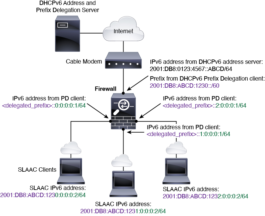
The following example shows the ASA receiving an IP address on the outside interface using the DHCPv6 address client. It also gets a delegated prefix using the DHCPv6 Prefix Delegation client. The ASA subnets the delegated prefix into /64 networks and assigns global IPv6 addresses to its inside interfaces dynamically using the delegated prefix plus a manually configured subnet (::0, ::1, or ::2) and IPv6 address (0:0:0:1) per interface. SLAAC clients connected to those inside interfaces obtain IPv6 addresses on each /64 subnet.

IPv6 Prefix Delegation /62 Subnet Example

The following example shows the ASA subnetting the prefix into 4 /62 subnets: 2001:DB8:ABCD:1230::/62, 2001:DB8:ABCD:1234::/62, 2001:DB8:ABCD:1238::/62, and 2001:DB8:ABCD:123C::/62. The ASA uses one of 4 available /64 subnets on 2001:DB8:ABCD:1230::/62 for its inside network (::0). You can then manually use additional /62 subnets for downstream routers. The router shown uses 3 of 4 available /64 subnets on 2001:DB8:ABCD:1234::/62 for its inside interfaces (::4, ::5, and ::6). In this case, the inside router interfaces cannot dynamically obtain the delegated prefix, so you need to view the delegated prefix on the ASA, and then use that prefix for your router configuration. Usually, ISPs delegate the same prefix to a given client when the lease expires, but if the ASA receives a new prefix, you will have to modify the router configuration to use the new prefix.


Enable the IPv6 Prefix Delegation Client

Enable the DHCPv6 Prefix Delegation client on one or more interfaces. The ASA obtains one or more IPv6 prefixes that it can subnet and assign to inside networks. Typically, the interface on which you enable the prefix delegation client obtains its IP address using the DHCPv6 address client; only other ASA interfaces use addresses derived from the delegated prefix.

Before you begin
  • This feature is only supported in routed firewall mode.

  • This feature is not supported in multiple context mode.

  • This feature is not supported in clustering.

  • You cannot configure this feature on a management-only interface.

  • When you use Prefix Delegation, you must set the ASA IPv6 neighbor discovery router advertisement interval to be much lower than the preferred lifetime of the prefix assigned by the DHCPv6 Server to prevent IPv6 traffic interruption. For example, if the DHCPv6 server sets the preferred Prefix Delegation lifetime to 300 seconds, you should set the ASA RA interval to be 150 seconds. To set the preferred lifetime, use the show ipv6 general-prefix command. To set the ASA RA interval, see Configure IPv6 Neighbor Discovery; the default is 200 seconds.

Procedure

Step 1

Choose Configuration > Device Setup > Interface Settings > Interfaces.

Step 2

Choose an interface, and click Edit.

The Edit Interface dialog box appears with the General tab selected.

Step 3

Click the IPv6 tab.

Step 4

In the Interface IPv6 DHCP area, click the Client Prefix Delegation Name radio button, and enter the prefix name.

Step 5

(Optional) In the Prefix Hint field, provide one or more hints about the delegated prefix you want to receive.

Typically you want to request a particular prefix length, such as ::/60, or if you have received a particular prefix before and want to ensure you get it again when the lease expires, you can enter the whole prefix as the hint (2001:DB8:ABCD:1230::/60). If you enter multiple hints (different prefixes or lengths), then it is up to the DHCP server which hint to honor, or whether to honor the hint at all.

Step 6

Click OK.

You return to the Configuration > Device Setup > Interface Settings > Interfaces pane.

Step 7

Click Apply.

Step 8

See Configure a Global IPv6 Address to assign a subnet of the prefix as the global IP address for an ASA interface.

Step 9

(Optional) See Configure the DHCPv6 Stateless Server to provide domain-name and server parameters to SLAAC clients.

Step 10

(Optional) See Configure IPv6 Network Settings to advertise the prefix(es) with BGP.


Configure a Global IPv6 Address

To configure a global IPv6 address for any routed mode interface and for the transparent or routed mode BVI, perform the following steps.

DHCPv6 and prefix delegation options are not supported with multiple context mode.


Note

Configuring the global address automatically configures the link-local address, so you do not need to configure it separately. For bridge groups, configuring the global address on the BVI automatically configures link-local addresses on all member interfaces.

For subinterfaces, we recommend that you also set the MAC address manually, because they use the same burned-in MAC address of the parent interface. IPv6 link-local addresses are generated based on the MAC address, so assigning unique MAC addresses to subinterfaces allows for unique IPv6 link-local addresses, which can avoid traffic disruption in certain instances on the ASA. See Configure the Manual MAC Address, MTU, and TCP MSS.


Before you begin

  • In multiple context mode, complete this procedure in the context execution space. To change from the system to a context configuration, in the Configuration > Device List pane, double-click the context name under the active device IP address.

Procedure


Step 1

Choose Configuration > Device Setup > Interface Settings > Interfaces.

Step 2

Choose an interface, and click Edit.

The Edit Interface dialog box appears with the General tab selected.

In transparent mode or for a bridge group in routed mode, select a BVI. For transparent mode, you can also select a management-only interface.

Step 3

Click the IPv6 tab.

Step 4

Check the Enable IPv6 check box.

Step 5

(Optional) To enforce the use of Modified EUI-64 format interface identifiers in IPv6 addresses on a local link, check the Enforce EUI-64 check box.

Step 6

(Routed interface) Configure the global IPv6 address using one of the following methods.

  • Stateless autoconfiguration—In the Interface IPv6 Addresses area, check the Enable address autoconfiguration check box.

    Enabling stateless autconfiguration on the interface configures IPv6 addresses based upon prefixes received in Router Advertisement messages. A link-local address, based on the Modified EUI-64 interface ID, is automatically generated for the interface when stateless autoconfiguration is enabled.

    Note 

    Although RFC 4862 specifies that hosts configured for stateless autoconfiguration do not send Router Advertisement messages, the ASA does send Router Advertisement messages in this case. Check the Suppress RA check box to suppress messages.

    If you want to install a default route, choose DHCP or Ignore from the drop-down menu. DHCP specifies the ASA only uses a default route from Router Advertisements that come from a trusted source (in other words, from the same server that provided the IPv6 address). Ignore specifies that Router Advertisements can be sourced from another network, which can be a riskier method.

  • Manual configuration—To manually configure a global IPv6 address:

    1. In the Interface IPv6 Addresses area, click Add.

      The Add IPv6 Address for Interface dialog box appears.

    2. In the Address/Prefix Length field, the value you enter depends on the method you want to use:

      • Full global address—If you want to manually enter the entire address, enter the full address plus the prefix length.

      • Modified EUI 64 format—Enter the IPv6 prefix and length, and then check the EUI 64 check box to generate the interface ID using the Modified EUI-64 format. For example, 2001:0DB8::BA98:0:3210/48 (full address) or 2001:0DB8::/48 (prefix, with EUI 64 checked).

      • Delegated Prefix—To derive the IPv6 prefix from the delegated prefix, enter the IPv6 address and length. Then enter the prefix name that you configured for the DHCPv6 Prefix Delegation client (See Enable the IPv6 Prefix Delegation Client) in the Prefix Name field, and click Add.

        Typically, the delegated prefix will be /60 or smaller so you can subnet to multiple /64 networks. /64 is the supported subnet length if you want to support SLAAC for connected clients. You should specify an address that completes the /60 subnet, for example ::1:0:0:0:1. Enter :: before the address in case the prefix is smaller than /60. For example, if the delegated prefix is 2001:DB8:1234:5670::/60, then the global IP address assigned to this interface is 2001:DB8:1234:5671::1/64. The prefix that is advertised in router advertisements is 2001:DB8:1234:5671::/64. In this example, if the prefix is smaller than /60, the remaining bits of the prefix will be 0's as indicated by the leading ::. For example, if the prefix is 2001:DB8:1234::/48, then the IPv6 address will be 2001:DB8:1234::1:0:0:0:1/64.

    3. Click OK.

  • Obtain an address using DHCPv6:

    1. In the Interface IPv6 DHCP area, check the Enable DHCP check box.

    2. (Optional) Check the Enable Default check box to obtain a default route from Router Advertisements.

Step 7

(BVI interface) Manually assign a global address to the BVI. For a management interface in Transparent mode, use this method as well.

  1. In the Interface IPv6 Addresses area, click Add.

    The Add IPv6 Address for Interface dialog box appears.

  2. In the Address/Prefix Length field, enter the full global IPv6 address along with the IPv6 prefix length.

  3. Click OK.

Step 8

Click OK.

You return to the Configuration > Device Setup > Interface Settings > Interfaces pane.


(Optional) Configure the Link-Local Addresses Automatically

If you do not want to configure a global address, and only need to configure a link-local address, you have the option of generating the link-local addresses based on the interface MAC addresses (Modified EUI-64 format. Because MAC addresses use 48 bits, additional bits must be inserted to fill the 64 bits required for the interface ID.)

To automatically configure the link-local addresses for an interface, perform the following steps.

Before you begin

Supported in routed mode only.

Procedure


Step 1

Choose Configuration > Device Setup > Interface Settings > Interfaces.

Step 2

Select an interface, and click Edit.

For bridge groups in routed mode, choose the BVI.

The Edit Interface dialog box appears with the General tab selected.

Step 3

Click the IPv6 tab.

Step 4

In the IPv6 configuration area, check the Enable IPv6 check box.

This option enables IPv6 and automatically generates the link-local address using the Modified EUI-64 interface ID based on the interface MAC address.

For bridge groups in routed mode, enabling IPv6 for the BVI generates link-local addresses for all member interfaces.

Step 5

Click OK.


(Optional) Configure the Link-Local Addresses Manually

If you do not want to configure a global address, and only need to configure a link-local address, you have the option of manually defining the link-local address. Note that we recommend automatically assigning the link-local address based on the Modified EUI-64 format. For example, if other devices enforce the use of the Modified EUI-64 format, then a manually-assigned link-local address may cause packets to be dropped.

To assign a link-local address to an interface, perform the following steps.

Procedure


Step 1

Choose Configuration > Device Setup > Interface Settings > Interfaces.

Step 2

Select an interface, and click Edit.

For bridge groups, choose a bridge group member interface.

The Edit Interface dialog box appears with the General tab selected.

Step 3

Click the IPv6 tab.

Step 4

(Optional) To enforce the use of Modified EUI-64 format interface identifiers in IPv6 addresses on a local link, check the Enforce EUI-64 check box.

Step 5

To set the link-local address, enter an address in the Link-local address field.

A link-local address should start with FE8, FE9, FEA, or FEB, for example fe80::20d:88ff:feee:6a82. See IPv6 Addresses for more information about IPv6 addressing.

Step 6

Click OK.


Configure IPv6 Neighbor Discovery

The IPv6 neighbor discovery process uses ICMPv6 messages and solicited-node multicast addresses to determine the link-layer address of a neighbor on the same network (local link), verify the readability of a neighbor, and keep track of neighboring routers.

Nodes (hosts) use neighbor discovery to determine the link-layer addresses for neighbors known to reside on attached links and to quickly purge cached values that become invalid. Hosts also use neighbor discovery to find neighboring routers that are willing to forward packets on their behalf. In addition, nodes use the protocol to actively keep track of which neighbors are reachable and which are not, and to detect changed link-layer addresses. When a router or the path to a router fails, a host actively searches for functioning alternates.

Procedure


Step 1

Choose Configuration > Device Setup > Interface Settings > Interfaces.

Step 2

Choose the IPv6 interface on which to configure IPv6 neighbor settings, and click Edit.

Step 3

Click the IPv6 tab.

Step 4

Enter the number of allowed DAD Attempts.

Values range from 0 to 600. A 0 value disables DAD processing on the specified interface. The default is 1 message.

DAD ensures the uniqueness of new unicast IPv6 addresses before they are assigned, and ensures that duplicate IPv6 addresses are detected in the network on a link basis. The ASA uses neighbor solicitation messages to perform DAD.

When a duplicate address is identified, the state of the address is set to DUPLICATE, the address is not used, and the following error message is generated:


325002: Duplicate address ipv6_address/MAC_address on interface

If the duplicate address is the link-local address of the interface, the processing of IPv6 packets is disabled on the interface. If the duplicate address is a global address, the address is not used.

Step 5

Enter the NS Interval in milliseconds to set the interval between IPv6 neighbor solicitation retransmissions.

Valid values for the value argument range from 1000 to 3600000 milliseconds.

Neighbor solicitation messages (ICMPv6 Type 135) are sent on the local link by nodes attempting to discover the link-layer addresses of other nodes on the local link. After receiving a neighbor solicitation message, the destination node replies by sending a neighbor advertisement message (ICPMv6 Type 136) on the local link.

After the source node receives the neighbor advertisement, the source node and destination node can communicate. Neighbor solicitation messages are also used to verify the reachability of a neighbor after the link-layer address of a neighbor is identified. When a node wants to verifying the reachability of a neighbor, the destination address in a neighbor solicitation message is the unicast address of the neighbor.

Neighbor advertisement messages are also sent when there is a change in the link-layer address of a node on a local link.

Step 6

Enter the Reachable Time in seconds to set how long a remote IPv6 node is reachable.

Set the reachable time between 0 to 3600000 milliseconds. When you set the time to 0, then the reachable time is sent as undetermined. It is up to the receiving devices to set and track the reachable time value.

The neighbor reachable time enables detecting unavailable neighbors. Shorter configured times enable detecting unavailable neighbors more quickly, however, shorter times consume more IPv6 network bandwidth and processing resources in all IPv6 network devices. Very short configured times are not recommended in normal IPv6 operation.

Step 7

Enter the RA Lifetime in seconds to set the length of time that nodes on the local link consider the ASA as the default router on the link.

Values range from 0 to 9000 seconds. Entering 0 indicates that the ASA should not be considered a default router on the selected interface.

Step 8

Check the Suppress RA check box to suppress router advertisements.

Router advertisement messages (ICMPv6 Type 134) are automatically sent in response to router solicitation messages (ICMPv6 Type 133). Router solicitation messages are sent by hosts at system startup so that the host can immediately autoconfigure without needing to wait for the next scheduled router advertisement message.

You may want to disable these messages on any interface for which you do not want the ASA to supply the IPv6 prefix (for example, the outside interface).

Enabling this option causes the ASA to appear as a regular IPv6 neighbor on the link and not as an IPv6 router.

Step 9

Enter the RA Interval to set the interval between IPv6 router advertisement transmissions.

Valid values range from 3 to 1800 seconds. The default is 200 seconds.

To add a router advertisement transmission interval value in milliseconds instead, check the RA Interval in Milliseconds check box, and enter a value from 500 to 1800000.

Step 10

Check the Hosts should use DHCP for address config check box to inform IPv6 autoconfiguration clients that they should use DHCPv6 to obtain addresses, in addition to the derived stateless autoconfiguration address.

This option sets the Managed Address Config flag in the IPv6 router advertisement packet.

Step 11

Check the Hosts should use DHCP for non-address config check box to inform IPv6 autoconfiguration clients that they should use DHCPv6 to obtain additional information from DHCPv6, such as the DNS server address.

This option sets the Other Address Config flag in the IPv6 router advertisement packet.

Step 12

Configure which IPv6 prefixes are included in IPv6 router advertisements.

  1. In the Interface IPv6 Prefixes area, click Add.

  2. Enter the Address/Prefix Length or check the Default check box to use the default prefix.

  3. Check the No Auto-Configuration check box to force hosts to configure the IPv6 address manually. Hosts on the local link with the specified prefix cannot use IPv6 autoconfiguration.

  4. Check the No Advertisements check box to disable prefix advertisement.

  5. Check the Off Link check box to configure the specified prefix as off-link. The prefix will be advertised with the L-bit clear. The prefix will not be inserted into the routing table as a Connected prefix.

  6. In the Prefix Lifetime area, specify a Lifetime Duration or Lifetime Expiration Date.

    After the preferred lifetime expires, the address goes into a deprecated state; while an address is in a deprecated state, its use is discouraged, but not strictly forbidden. After the valid lifetime expires, the address becomes invalid and cannot be used. The valid lifetime must be greater than or equal to the preferred lifetime.

    • Lifetime Duration—Values range from 0 to 4294967295. The default valid lifetime is 2592000 (30 days). The default preferred lifetime is 604800 (7 days). The maximum value represents infinity.

    • Lifetime Expiration Date—Choose a valid and preferred month and day from the drop-down lists, and then enter a time in hh:mm format.

  7. Click OK to save your settings.

Step 13

Click OK.

Step 14

Configure a static IPv6 neighbor.

The following guidelines and limitations apply for configuring a static IPv6 neighbor:

  • This feature is similar to adding a static ARP entry. If an entry for the specified IPv6 address already exists in the neighbor discovery cache—learned through the IPv6 neighbor discovery process—the entry is automatically converted to a static entry. These entries are stored in the configuration when the copy command is used to store the configuration.

  • Static entries in the IPv6 neighbor discovery cache are not modified by the neighbor discovery process.

  • The ICMP syslogs generated are caused by a regular refresh of IPv6 neighbor entries. The ASA default timer for IPv6 neighbor entry is 30 seconds, so the ASA would generate ICMPv6 neighbor discovery and response packets about every 30 seconds. If the ASA has both failover LAN and state interfaces configured with IPv6 addresses, then every 30 seconds, ICMPv6 neighbor discovery and response packets will be generated by both ASAs for both configured and link-local IPv6 addresses. In addition, each packet will generate several syslogs (ICMP connection and local-host creation or teardown), so it may appear that constant ICMP syslogs are being generated. The refresh time for IPV6 neighbor entry is configurable on the regular data interface, but not configurable on the failover interface. However, the CPU impact for this ICMP neighbor discovery traffic is minimal.

See also View and Clear Dynamically Discovered Neighbors.

  1. Choose Configuration > Device Management > Advanced > IPv6 Neighbor Discovery Cache.

  2. Click Add.

    The Add IPv6 Static Neighbor dialog box appears.

  3. From the Interface Name drop-down list, choose an interface on which to add the neighbor.

  4. In the IP Address field, enter the IPv6 address that corresponds to the local data-link address, or click the ellipsis (...) to browse for an address.

  5. In the MAC address field, enter the local data-line (hardware) MAC address.

  6. Click OK.

Step 15

Click Apply to save the running configuration.


View and Clear Dynamically Discovered Neighbors

When a host or node communicates with a neighbor, the neighbor is added to the neighbor discovery cache. The neighbor is removed from the cache when there is no longer any communication with that neighbor.

To view dynamically discovered neighbors and clear these neighbors from the IPv6 neighbor discovery cache, perform the following steps:

Procedure


Step 1

Choose Monitoring > Interfaces > IPv6 Neighbor Discovery Cache.

You can view all static and dynamically discovered neighbors from the IPv6 Neighbor Discovery Cache pane.

Step 2

To clear all dynamically discovered neighbors from the cache, click Clear Dynamic Neighbor Entries.

The dynamically discovered neighbor is removed from the cache.

Note 

This procedure clears only dynamically discovered neighbors from the cache; it does not clear static neighbors.


Monitoring Routed and Transparent Mode Interfaces

You can monitor interface statistics, status, PPPoE, and more.


Note

For the Firepower 1000, 2100 and the Firepower 4100/9300, some statistics are not shown using the ASA commands. You must view more detailed interface statistics using FXOS commands.

  • /eth-uplink/fabric# show interface

  • /eth-uplink/fabric# show port-channel

  • /eth-uplink/fabric/interface# show stats

For the Firepower 2100 in Platform mode, see also the following FXOS connect local-mgmt commands:

  • (local-mgmt)# show portmanager counters

  • (local-mgmt)# show lacp

  • (local-mgmt)# show portchannel

See the FXOS troubleshooting guide for more information.


Interface Statistics and Information

  • Monitoring  > Interfaces > Interface Graphs

    Lets you view interface statistics in graph or table form. If an interface is shared among contexts, the ASA shows only statistics for the current context. The number of statistics shown for a subinterface is a subset of the number of statistics shown for a physical interface.

  • Monitoring > Interfaces > Interface Graphs > Graph/Table

    Shows a graph for the selected statistics. The Graph window can show up to four graphs and tables at a time. By default, the graph or table displays the real-time statistics. If you enable History Metrics, you can view statistics for past time periods.

DHCP Information

  • Monitoring > Interfaces > DHCP > DHCP Client Lease Information.

    This screen displays configured DHCP client IP addresses.

  • Monitoring > Interfaces > DHCP > IPV6 DHCP Client PD Statistics

    This screen shows DHCPv6 Prefix Delegation client statistics and shows the output of the number of messages sent and received.

  • Monitoring > Interfaces > DHCP > IPV6 DHCP Client Statistics

    This screen shows DHCPv6 client statistics and shows the output of the number of messages sent and received.

  • Monitoring > Interfaces > DHCP > IPV6 DHCP Interface Statistics

    This screen displays DHCPv6 information for all interfaces. If the interface is configured for DHCPv6 stateless server configuration (see Configure the DHCPv6 Stateless Server), this screen lists the DHCPv6 pool that is being used by the server. If the interface has DHCPv6 address client or Prefix Delegation client configuration, this screen shows the state of each client and the values received from the server. This screen also shows message statistics for the DHCP server or client.

  • Monitoring > Interfaces > DHCP > IPV6 DHCP HA Statistics

    This screen shows the transaction statistics between failover units, including how many times the DUID information was synced between the units.

Static Route Tracking

  • Monitoring > Interfaces > interface connection > Track Status

    Displays information about the tracked object.

  • Monitoring > Interfaces > interface connection > Monitoring Statistics

    Displays statistics for the SLA monitoring process.

PPPoE

  • Monitoring > Interfaces > PPPoE Client > PPPoE Client Lease Information

    Displays information about current PPPoE connections.

Dynamic ACLs

Monitoring > Interfaces > Dynamic ACLs

Shows a table of the Dynamic ACLs, which are functionally identical to the user-configured ACLs except that they are created, activated and deleted automatically by the ASA. These ACLs do not show up in the configuration and are only visible in this table. They are identified by the “(dynamic)” keyword in the ACL header.

Examples for Routed and Transparent Mode Interfaces

Transparent Mode Example with 2 Bridge Groups

The following example for transparent mode includes two bridge groups of three interfaces each, plus a management-only interface:


interface gigabitethernet 0/0
  nameif inside1
  security-level 100
  bridge-group 1
  no shutdown
interface gigabitethernet 0/1
  nameif outside1
  security-level 0
  bridge-group 1
  no shutdown
interface gigabitethernet 0/2
  nameif dmz1
  security-level 50
  bridge-group 1
  no shutdown
interface bvi 1
  ip address 10.1.3.1 255.255.255.0 standby 10.1.3.2

interface gigabitethernet 1/0
  nameif inside2
  security-level 100
  bridge-group 2
  no shutdown
interface gigabitethernet 1/1
  nameif outside2
  security-level 0
  bridge-group 2
  no shutdown
interface gigabitethernet 1/2
  nameif dmz2
  security-level 50
  bridge-group 2
  no shutdown
interface bvi 2
  ip address 10.3.5.8 255.255.255.0 standby 10.3.5.9

interface management 0/0
  nameif mgmt
  security-level 100
  ip address 10.2.1.1 255.255.255.0 standby 10.2.1.2
  no shutdown

Switched LAN Segment Example with 2 Bridge Groups

The following example configures 2 bridge groups with 3 interfaces each and one regular routed interface for outside. Bridge group 1 is inside and bridge group 2 is dmz with public web servers. The bridge group member interfaces can communicate freely within the bridge group because each member is at the same security level, and we enabled same security communication. Although the inside member security level is 100 and the dmz member security level is also 100, these security levels do not apply to inter-BVI communications; only the BVI security levels affect inter-BVI traffic. The security levels of the BVIs and outside (100, 50, and 0) implicitly permit traffic from inside to dmz and inside to outside; and from dmz to outside. An access rule is applied to outside to allow traffic to the servers on dmz.


interface gigabitethernet 1/1
  nameif outside
  security-level 0
  ip address dhcp setroute
  no shutdown
!
interface gigabitethernet 1/2
  nameif inside1
  security-level 100
  bridge-group 1
  no shutdown
interface gigabitethernet 1/3
  nameif inside2
  security-level 100
  bridge-group 1
  no shutdown
interface gigabitethernet 1/4
  nameif inside3
  security-level 100
  bridge-group 1
  no shutdown
!
interface bvi 1
  nameif inside
  security-level 100
  ip address 10.10.10.1 255.255.255.0
!
interface gigabitethernet 1/5
  nameif dmz1
  security-level 100
  bridge-group 2
  no shutdown
interface gigabitethernet 1/6
  nameif dmz2
  security-level 100
  bridge-group 2
  no shutdown
interface gigabitethernet 1/7
  nameif dmz3
  security-level 100
  bridge-group 2
  no shutdown
!
interface bvi 2
  nameif dmz
  security-level 50
  ip address 209.165.201.1 255.255.255.224
!
same-security-traffic permit inter-interface
!
# Assigns IP addresses to inside hosts
dhcpd address 10.10.10.2-10.10.10.200 inside
dhcpd enable inside
!
# Applies interface PAT for inside traffic going outside
nat (inside1,outside) source dynamic any interface
nat (inside2,outside) source dynamic any interface
nat (inside3,outside) source dynamic any interface 
!
# Allows outside traffic to each server for specific applications
object network server1
  host 209.165.201.2
object network server2
  host 209.165.201.3
object network server3
  host 209.165.201.4
!
# Defines mail services allowed on server3
object-group service MAIL
  service-object tcp destination eq pop3
  service-object tcp destination eq imap4
  service-object tcp destination eq smtp
!
# Allows access from outside to servers on the DMZ
access-list SERVERS extended permit tcp any object server1 eq www
access-list SERVERS extended permit tcp any object server2 eq ftp
access-list SERVERS extended permit tcp any object server3 object-group MAIL 
access-group SERVERS in interface outside

History for Routed and Transparent Mode Interfaces

Feature Name

Platform Releases

Feature Information

IPv6 Neighbor Discovery

7.0(1)

We introduced this feature.

We introduced the following screens:

Monitoring > Interfaces > IPv6 Neighbor Discovery Cache.
Configuration > Device Management > Advanced > IPv6 Neighbor Discovery Cache.
Configuration > Device Setup > Interface Settings > Interfaces > IPv6.

IPv6 support for transparent mode

8.2(1)

IPv6 support was introduced for transparent firewall mode.

Bridge groups for transparent mode

8.4(1)

If you do not want the overhead of security contexts, or want to maximize your use of security contexts, you can group interfaces together in a bridge group, and then configure multiple bridge groups, one for each network. Bridge group traffic is isolated from other bridge groups. You can configure up to eight bridge groups of four interfaces each in single mode or per context.

We modified or introduced the following screens:


Configuration > Device Setup > Interface Settings > Interfaces

Configuration > Device Setup > Interface Settings > Interfaces > Add/Edit Bridge Group Interface

Configuration > Device Setup > Interface Settings > Interfaces > Add/Edit Interface

Address Config Flags for IPv6 DHCP Relay

9.0(1)

We modified the following screen: Configuration > Device Setup > Interfaces > IPv6.

Transparent mode bridge group maximum increased to 250

9.3(1)

The bridge group maximum was increased from 8 to 250 bridge groups. You can configure up to 250 bridge groups in single mode or per context in multiple mode, with 4 interfaces maximum per bridge group.

We modified the following screens:

Configuration > Device Setup > Interface Settings > Interfaces

Configuration > Device Setup > Interface Settings > Interfaces > Add/Edit Bridge Group Interface


Configuration > Device Setup > Interface Settings > Interfaces > Add/Edit Interface

Transparent mode maximum interfaces per bridge group increased to 64

9.6(2)

The maximum interfaces per bridge group was increased from 4 to 64.

We did not modify any screens.

IPv6 DHCP

9.6(2)

The ASA now supports the following features for IPv6 addressing:

  • DHCPv6 Address client—The ASA obtains an IPv6 global address and optional default route from the DHCPv6 server.

  • DHCPv6 Prefix Delegation client—The ASA obtains delegated prefix(es) from a DHCPv6 server. The ASA can then use these prefixes to configure other ASA interface addresess so that StateLess Address Auto Configuration (SLAAC) clients can autoconfigure IPv6 addresses on the same network.

  • BGP router advertisement for delegated prefixes

  • DHCPv6 stateless server—The ASA provides other information such as the domain name to SLAAC clients when they send Information Request (IR) packets to the ASA. The ASA only accepts IR packets, and does not assign addresses to the clients.

We added or modified the following screens:

Configuration > Device Setup > Interface Settings > Interfaces > Add Interface > IPv6

Configuration > Device Management > DHCP > DHCP Pool

Configuration > Device Setup > Routing > BGP > IPv6 Family > Networks

Monitoring > interfaces > DHCP

Integrated Routing and Bridging

9.7(1)

Integrated Routing and Bridging provides the ability to route between a bridge group and a routed interface. A bridge group is a group of interfaces that the ASA bridges instead of routes. The ASA is not a true bridge in that the ASA continues to act as a firewall: access control between interfaces is controlled, and all of the usual firewall checks are in place. Previously, you could only configure bridge groups in transparent firewall mode, where you cannot route between bridge groups. This feature lets you configure bridge groups in routed firewall mode, and to route between bridge groups and between a bridge group and a routed interface. The bridge group participates in routing by using a Bridge Virtual Interface (BVI) to act as a gateway for the bridge group. Integrated Routing and Bridging provides an alternative to using an external Layer 2 switch if you have extra interfaces on the ASA to assign to the bridge group. In routed mode, the BVI can be a named interface and can participate separately from member interfaces in some features, such as access rules and DHCP server.

The following features that are supported in transparent mode are not supported in routed mode: multiple context mode, ASA clustering. The following features are also not supported on BVIs: dynamic routing and multicast routing.

We modified the following screens:

Configuration > Device Setup > Interface Settings > Interfaces

Configuration > Device Setup > Routing > Static Routes

Configuration > Device Management > DHCP > DHCP Server

Configuration > Firewall > Access Rules

Configuration > Firewall > EtherType Rules

31-bit Subnet Mask

9.7(1)

For routed interfaces, you can configure an IP address on a 31-bit subnet for point-to-point connections. The 31-bit subnet includes only 2 addresses; normally, the first and last address in the subnet is reserved for the network and broadcast, so a 2-address subnet is not usable. However, if you have a point-to-point connection and do not need network or broadcast addresses, a 31-bit subnet is a useful way to preserve addresses in IPv4. For example, the failover link between 2 ASAs only requires 2 addresses; any packet that is transmitted by one end of the link is always received by the other, and broadcasting is unnecessary. You can also have a directly-connected management station running SNMP or Syslog. This feature is not supported for BVIs for bridge groups or with multicast routing.

We modified the following screens:

Configuration > Device Setup > Interface Settings > Interfaces > Add Interface > General