Dynamic On-Demand Tunnels


Note


To achieve simplification and consistency, the Cisco SD-WAN solution has been rebranded as Cisco Catalyst SD-WAN. In addition, from Cisco IOS XE SD-WAN Release 17.12.1a and Cisco Catalyst SD-WAN Release 20.12.1, the following component changes are applicable: Cisco vManage to Cisco Catalyst SD-WAN Manager, Cisco vAnalytics to Cisco Catalyst SD-WAN Analytics, Cisco vBond to Cisco Catalyst SD-WAN Validator, Cisco vSmart to Cisco Catalyst SD-WAN Controller, and Cisco Controllers to Cisco Catalyst SD-WAN Control Components. See the latest Release Notes for a comprehensive list of all the component brand name changes. While we transition to the new names, some inconsistencies might be present in the documentation set because of a phased approach to the user interface updates of the software product.
Table 1. Feature History

Feature Name

Release Information

Description

Dynamic On-Demand Tunnels

Cisco IOS XE Catalyst SD-WAN Release 17.3.1a

Cisco vManage Release 20.3.1

This feature enables you to configure an Inactive state for tunnels between edge devices, reducing performance demands on devices and reducing network traffic.

Dynamic On-Demand Tunnels with Transport Gateways

Cisco Catalyst SD-WAN Control Components Release 20.12.1

Cisco IOS XE Catalyst SD-WAN Release 17.12.1a

A transport gateway can serve as the hub between two spoke devices, providing the backup route that is necessary for spoke-to-spoke on-demand tunnels to operate.

Using a transport gateway as the hub simplifies the process of enabling on-demand tunnels. This method does not require any change to control policy on Cisco SD-WAN Controllers.

Information About On-Demand Tunnels

Cisco Catalyst SD-WAN supports dynamic on-demand tunnels between any two Cisco Catalyst SD-WAN spoke devices. These tunnels are triggered to be set up only when there is traffic between the two devices. After the flow of traffic between the devices stops, a user-configurable inactivity timer starts, and after the configured time, the tunnel between the devices is removed. The on-demand link between the two devices is then considered to be inactive. In this inactive state, it does not use network bandwidth and does not affect device performance.

Backup Route and Reactivating the Tunnel

To enable two spoke device peers to use on-demand tunnels, they must have an alternate route, a backup route, through a hub. Using the backup route, either spoke device can resume traffic flow between the two spokes, which reactivates the tunnel to handle the traffic directly from peer to peer.

Advantages

On-demand tunnels offer the following advantages:

  • Improved performance, especially for less-powerful platforms operating in a full-mesh network.

  • Improved latency in hub-and-spoke deployments when on-demand tunnels are used between spokes.

  • Reduced bandwidth use in the network because tunnels in Inactive state do not require Bidirectional Forwarding Detection (BFD) probes, so there is less BFD traffic produced in the network.

  • Direct tunnels between spokes, while also optimizing CPU and memory usage.

Mechanism

When you configure a site to use dynamic tunnels, the on-demand functionality is enabled. In this mode of operation, Cisco Catalyst SD-WAN edge routers do not bring up direct tunnels to other sites that are also enabled with on-demand functionality.

Cisco Catalyst SD-WAN selects one or more edge routers (typically centrally located routers) to act as backup forwarding node(s), providing a secondary path for traffic between two nodes. The backup node(s) are not enabled for on-demand. All on-demand sites form static tunnels with the backup node(s). The backup node(s) provide a static backup route for traffic between two nodes that have on-demand enabled.

The first packet of traffic between two nodes is routed though the static backup path, and triggers the on-demand tunnel to become active between the sites. The backup path continues to forward traffic until the direct path becomes active.

All on-demand sites learn the TLOCs and prefixes of all other on-demand remote sites. The prefixes also have a backup path set up through Cisco Catalyst SD-WAN Controller control policy. So in the control plane, the on-demand tunnel network has the same state as a full-mesh tunnel network, including a backup path. The control plane downloads to the data plane, routes, with the backup path and remote TLOCs that represent a potential direct path between any two sites, but it does not set up a direct path tunnel to remote TLOCs.

Traffic from either end of the on-demand tunnel triggers setting up the tunnel. This enables on-demand tunnels to accommodate network address translation (NAT) traversal.

The on-demand tunnel feature introduces two states for the on-demand branch site:

  • Inactive: The on-demand tunnel is not set up with the remote site. There is no active traffic to or from the remote site. Remote site TLOCs are inactive - no bidirectional forwarding detection (BFD) is set up, the prefix is installed with the inactive paths, and the backup path is set as the path to forward any traffic. The inactive path detects flows and triggers a direct site-to-site tunnel to be set up.

  • Active: The on-demand direct site-to-site tunnel is set up to the remote site. There is active traffic to or from the remote site. This state is identical to the case of a typical tunnel, where the remote TLOCs have BFD set up, and the prefix is installed with the direct path tunnel. In this state, tunnel activity is tracked. If there is no traffic for the “idle time” duration (default 10 minutes), the direct site-to-site tunnel is removed and the state changes to Inactive.

Steps in Illustrations

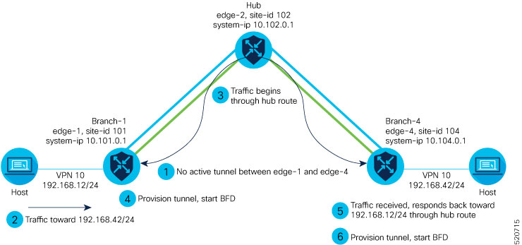
The figures below show the following steps that occur between two edge routers with an on-demand tunnel configured.

  1. There is no active tunnel between the two edge routers. edge-1 and edge-4 are in Inactive state.

  2. The host behind edge-1 initiates traffic toward the host behind edge-4.

  3. edge-1 forwards the traffic through the backup path using the hub or backup node to edge-4.

  4. edge-1 provisions the on-demand tunnel and begins bidirectional forwarding detection (BFD). edge-4 is now in Active state on edge-1.

  5. When edge-4 receives the return traffic for the host behind edge-1, it forwards the traffic through the backup path using the hub or backup node to edge-1.

  6. edge-4 provisions the on-demand tunnel and begins BFD. edge-1 is now in Active state on edge-4.

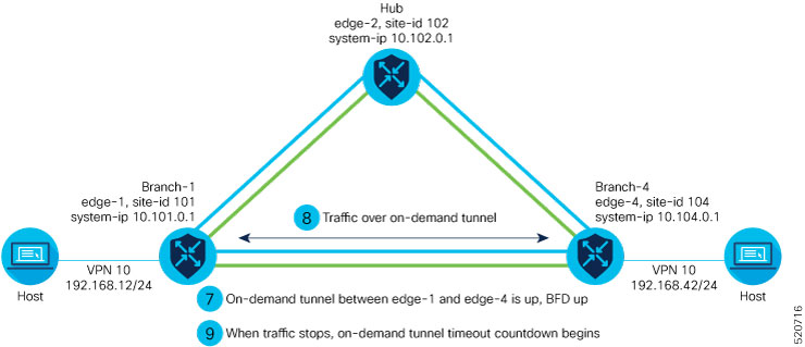
  7. At this point, the on-demand tunnel between edge-1 and edge-4 is up, and BFD is up.

  8. Traffic between the two edge devices takes the direct route through the on-demand tunnel.

  9. Both edge-1 and edge-4 track the traffic activity on the on-demand tunnel in both directions.

    If there is no traffic for the idle timeout duration, the on-demand tunnel is deleted, and the edge-1 and edge-4 devices go back to the Inactive state.

On-Demand Tunnels with a Transport Gateway

A transport gateway can serve as the hub between two spoke devices, providing the backup route that is necessary for spoke-to-spoke on-demand tunnels to operate. Using a transport gateway as the hub simplifies the process of enabling on-demand tunnels. This method does not require configuring control policy on Cisco SD-WAN Controllers.

For information about configuration, see Configure On-Demand Tunnels Using a Transport Gateway.

Prerequisites for On-Demand Tunnels

There are several prerequisites for using on-demand tunnels:

Prerequisites: OMP Settings

The Cisco Catalyst SD-WAN Controller send-path-limit must be more than the default 4.

Explanation: When on-demand tunnels are enabled, spokes use backup paths through the hub, so a higher path limit is necessary. The direct paths as well as the backup paths need to be advertised. To accommodate this, increase the Cisco Catalyst SD-WAN Controller send-path-limit to advertise all available paths. We recommend to use the maximum possible value.


Note


If there are too many Hub TLOCs configured in the on-demand tunnel control policy, the recommended value for send-path-limit is not enough always. In such cases, the on-demand tunnel feature will not work at all.

Starting from Cisco vManage Release 20.8.1 and Cisco IOS XE Catalyst SD-WAN Release 17.8.1a, the maximum send-path-limit is 32. In Cisco vManage Release 20.7.x and earlier releases, the maximum send-path-limit is 16.


For information about configuring Cisco SD-WAN Controller send-path-limit, see the routing configuration guides on the Cisco Catalyst SD-WAN Configuration Guides page.

Configure the OMP Send Path Limit Using Cisco SD-WAN Manager

  1. From the Cisco SD-WAN Manager menu, choose Configuration > Templates.

  2. Click Feature Templates.


    Note


    In Cisco vManage Release 20.7.x and earlier releases, Feature Templates is titled Feature.


  3. Click Add Template.

  4. Select a device and click Cisco OMP.

  5. In Basic Configuration, set the Number of Paths Advertised per Prefix to 16 (recommended).

Configure the OMP Send Path Limit Using a CLI Template

omp
 no shutdown
 send-path-limit 16
 graceful-restart

Prerequisites: Hub Device Traffic Engineering Service

On the hub device, the Traffic Engineering service (service TE) must be enabled.

Explanation: This ensures that the Cisco Catalyst SD-WAN Overlay Management Protocol (OMP) on the spoke devices accepts the backup path through the hub, which is being added as an intermediate path between the two spoke devices. Without this, the backup path through the hub would be considered invalid and unresolved by the spoke devices.

Enable the Traffic Engineering Service Using Cisco SD-WAN Manager

  1. In Cisco SD-WAN Manager, open Configuration > Templates.

  2. Click Feature Templates.


    Note


    In Cisco vManage Release 20.7.x and earlier releases, Feature Templates is titled Feature.


  3. Click Add Template.

  4. Select a platform.

  5. From VPN, select VPN.

  6. Ensure that in Basic Configuration, the VPN field is set to 0.

  7. From Service, click New Service and select TE.

  8. Click Add, and then click Update. The TE service appears in the table of services.

  9. Apply the VPN-0 template to the hub.

Enable the Traffic Engineering Service Using a CLI Template (Cisco IOS XE Catalyst SD-WAN Devices)

sdwan
 service TE vrf global
exit

Enable the Traffic Engineering Service Using a CLI Template (Cisco vEdge Devices)

vpn 0
 service TE
 exit

Prerequisites: Spoke Device ECMP Limit

On spoke devices, the ecmp-limit must be more than the default 4. Recommended: 16

Explanation: When on-demand tunnels are enabled, spoke devices create both direct and backup paths. To accommodate the need for more paths, increase the ecmp-limit.

Configure the ECMP Limit Using Cisco SD-WAN Manager

  1. From the Cisco SD-WAN Manager menu, choose Configuration > Templates.

  2. Click Feature Templates.


    Note


    In Cisco vManage Release 20.7.x and earlier releases, Feature Templates is titled Feature.


  3. Click Add Template.

  4. Select a device and click Cisco OMP.

  5. In Basic Configuration, set the ECMP Limit field to 16 (recommended).

Configure the ECMP Limit Using a CLI Template

omp
 no shutdown
 ecmp-limit       16

Note


You can view the current ecmp-limit using the show running-config omp command.


Restrictions for On-Demand Tunnels

  • On-demand tunnel Performance Routing (PfR) statistics collection starts fresh every time an on-demand tunnel is setup. PfR statistics are not cached for deleted on-demand tunnels after idle timeout.

  • Out of order (OOO) packets may occur when traffic moves from the backup path to the direct on-demand tunnel. Packets are forwarded by the Cisco Catalyst SD-WAN router as they are received.

  • Unidirectional flows do not trigger on-demand tunnel setup. They continue to use the backup path.

  • Multicast traffic does not trigger on-demand tunnel setup. It continues to use the backup path.

  • Do not configure a data policy that applies a set tloc-list action to an on-demand site TLOC. If configured, traffic will be dropped.

  • On-demand tunnels are not supported when the Pair Wise Key (PWK) IPSEc feature is enabled.

  • All TLOCs in the system are reset (disabled and then enabled) when you execute on-demand enable or no on-demand enable .

  • When an edge device provisions on-demand tunnels, it provisions to all the TLOCs on the remote site.

  • For a multi-home site to be in on-demand mode, you must configure on-demand enable on all of the systems at the site.

  • All edge devices using on-demand tunnels are kept active if there is a service or user traffic on any on-demand tunnel in either direction.

  • On-demand tunnels can be enabled between two sites only if both sites are enabled with on-demand mode.

  • The first packet to any host behind a remote site triggers on-demand tunnel setup to that remote site. Return traffic from that host triggers tunnel setup in the opposite direction.

  • All prefixes from on-demand remote sites must also have a backup path configured. If not, sites will not be able set up on-demand tunnels. The backup path is a static tunnel and must be always UP.

  • The setup or removal of on-demand tunnels does not affect overlay route (OMP) updates by Cisco Catalyst SD-WAN Controller, or service/LAN-side route updates (examples: OSPF or BGP).

  • If either the local site or the remote site is not in on-demand mode, static tunnels are set up between the sites.

Configure On-Demand Tunnels

The following procedures describe how to configure on-demand tunnels using different methods, including using control policy, or a simpler method using a transport gateway as a hub.

Configure On-Demand Tunnels Using Control Policy

To configure on-demand tunnels using the control policy method, do the following:

  1. Configure a control policy, as described in Configure a Centralized Control Policy for On-Demand Tunnels.

  2. On spoke devices, enable on-demand tunnels, as described in Enable On-Demand Tunnels on a Spoke Device Using Cisco SD-WAN Manager and Enable On-Demand Tunnels Using a CLI Template.

Configure a Centralized Control Policy for On-Demand Tunnels

Before You Begin

This procedure configures a centralized control policy on a Cisco Catalyst SD-WAN Controller to enable on-demand tunnels.

  • The Cisco Catalyst SD-WAN Controller centralized control policy must include the tloc-action backup action.

    Explanation: This ensures that the backup path through the hub for communication between all of the spoke devices.

  • The Cisco Catalyst SD-WAN Controller centralized control policy must accept all spoke prefix routes.

  • The Cisco Catalyst SD-WAN Controller centralized control policy must accept TLOCs of all spokes.

    For information about configuring a Cisco SD-WAN Controller centralized control policy, see the policies configuration guides on the Cisco Catalyst SD-WAN Configuration Guides page.

  • When configuring on-demand tunnels using a transport gateway, do not use the control policy procedure described here. For information, see Configure On-Demand Tunnels Using a Transport Gateway.

Configure Centralized Control Policy for On-Demand Tunnels Using Cisco SD-WAN Manager
  1. From the Cisco SD-WAN Manager menu, choose Configuration > Policies.

  2. Select Centralized Policy.

  3. Click Add Topology and select Custom Control (Route & TLOC).

  4. From Match Conditions, in Site , select one or more site lists, and click Accept.

  5. From Actions, in TLOC Action, select the Backup action.

  6. From TLOC List, select an existing TLOC list or create a new one.

Configure Centralized Control Policy for On-Demand Tunnels Using a CLI Template
viptela-policy:policy
 control-policy Dynamic-Tunnel-Control-Policy
    sequence 100
     match route
      site-list Branches
     !
     action accept
      set
       tloc-action backup
       tloc-list Hub-TLOCs
      !
     !
     sequence 200
      match tloc 
     !
     action accept 
    !
  default-action accept
 !
 lists
  site-list Branches
   site-id 200 
   site-id 300
  !
  tloc-list Hub-TLOCs
   tloc 10.0.0.1 color mpls encap ipsec
   tloc 10.0.0.1 color public-internet encap ipsec 
!
!
apply-policy
 site-list Branches
  control-policy Dynamic-Tunnel-Control-Policy out
 !
!

Configure On-Demand Tunnels Using a Transport Gateway

Before You Begin

Configure On-Demand Tunnels Using Transport Gateways

  1. On a router serving as the hub, providing a backup route between spokes, enable transport gateway functionality, as described in , in the Transport Gateway section of the Cisco Catalyst SD-WAN Routing Configuration Guide.

  2. On spoke devices, enable on-demand tunnels and configure the idle timeout, as described in Enable On-Demand Tunnels on a Spoke Device Using Cisco SD-WAN Manager.

Enable On-Demand Tunnels on a Spoke Device Using Cisco SD-WAN Manager

Before You Begin

  • See the Prerequisites for On-Demand Tunnels.

  • Do not enable on-demand on the hub device.

  • On the spoke devices, enable on-demand at the system level. In the case of multi-homed sites, enable on-demand on all systems at the site.

Enable On-Demand Tunnels on a Spoke Device

  1. From the Cisco SD-WAN Manager menu, choose Configuration > Templates.

  2. Click Feature Templates.


    Note


    In Cisco vManage Release 20.7.x and earlier releases, Feature Templates is titled Feature.


  3. Click Add Template.

  4. Select a device.

  5. From Basic Information, select Cisco System.

  6. Click Advanced.

  7. Enable On-demand Tunnel.

  8. (optional) Configure the On-demand Tunnel Idle Timeout time. The default idle timeout value is 10 minutes. Range: 1 to 65535 minutes

  9. Attach the System feature template to the device template for the spoke device.

Enable On-Demand Tunnels Using a CLI Template

For more information about using CLI templates, see CLI Add-On Feature Templates and CLI Templates. By default, CLI templates execute commands in global configuration mode.

Before You Begin

Enable On-Demand Tunnels

On the spoke devices, enable on-demand tunnels at the system level. In the case of multi-homed sites, enable on-demand on all systems in the site.

The default idle timeout value is 10 minutes. Range: 1 to 65535 minutes

Example

system 
     on-demand enable
     on-demand idle-timeout 10

Monitor the Status of On-Demand Tunnels

The following sections describe procedures for monitoring the status of on-demand tunnels.

View the Current Status of On-Demand Tunnels Using Cisco SD-WAN Manager

  1. From the Cisco SD-WAN Manager menu, choose Monitor > Devices.

    Cisco vManage Release 20.6.x and earlier: From the Cisco SD-WAN Manager menu, choose Monitor > Network.

  2. Select a device.

  3. Select Real Time.

  4. For Device Options, select one of the following:

    • On Demand Local: Displays the status of on-demand tunnels on the specified device.

    • On Demand Remote: Displays the status of on-demand tunnels on the specified device, and on all connected devices.

The output is equivalent to executing the show [sdwan] system on-demand [remote-system] [system-ip ip-address] CLI command. It displays the status of on-demand tunnels.

View a Chart of the On-Demand Tunnel Status Over Time in Cisco SD-WAN Manager

  1. From the Cisco SD-WAN Manager menu, choose Monitor > Devices.

    Cisco vManage Release 20.6.x and earlier: From the Cisco SD-WAN Manager menu, choose Monitor > Network.

  2. Select a device.

  3. From WAN, choose Tunnel.

  4. From the Chart Options drop-down list, select On-Demand Tunnel Status. The chart shows the status of tunnels as ACTIVE or INACTIVE. INACTIVE indicates that an on-demand tunnel is in Inactive mode.

View the Route to a Destination Device

Viewing the route between routers A and B can show whether the route is using an on-demand tunnel. On router A, use the traceroute command and enter router B as the destination. The command output shows whether the current route includes a hop at a hub device or whether the route is directly to the destination.

In the following examples, the router IP addresses are as follows:

  • Router A: 10.1.1.1

  • Router B: 10.1.1.2

  • Hub device: 10.100.1.100

No Active On-Demand Tunnel

In the following example, there is no active on-demand tunnel between routers A and B, so the route includes the hub device. Note that it takes two hops to reach router B.

RouterA#traceroute vrf 1 10.1.1.2 numeric
Type escape sequence to abort.
Tracing the route to 10.1.1.2
VRF info: (vrf in name/id, vrf out name/id)
1 10.100.1.100 10 msec 8 msec 0 msec
2 10.1.1.2 2 msec * 1 msec

Active On-Demand Tunnel

In the following example, there is an active on-demand tunnel between routers A and B, so the route from router A and to router B is direct.

RouterA#traceroute vrf 1 10.1.1.2 numeric
Type escape sequence to abort.
Tracing the route to 10.1.1.2
VRF info: (vrf in name/id, vrf out name/id)
1 10.1.1.2 1 msec

View OMP Routes

Viewing OMP routes can show the status of on-demand tunnels between two routers. Use the show sdwan omp routes command and view the STATUS column. The following table shows the possible values for this column, depending on whether an on-demand tunnel is active or not between two routers:

Table 2. Status of Routes, with or without an Active On-Demand Tunnel Between Two Routers

On-Demand Tunnel Between Routers A and B

STATUS for OMP Routes Between Routers A and B

STATUS for Backup Routes (through the Hub)

Not active

I, U, IA

(installed, unresolved, and inactive)

C, I, R

(chosen, installed, and resolved)

Active

C, I, R

(chosen, installed, and resolved)

R

(resolved)