Hub-and-Spoke

Hub-and-Spoke

Table 1. Feature History

Feature Name

Release Information

Description

Hub-and-Spoke Configuration

Cisco Catalyst SD-WAN Manager Release 20.12.1

Cisco IOS XE Catalyst SD-WAN Release 17.12.1a

Hub-and-spoke configuration simplifies the process of configuring a hub-and-spoke topology, making complex centralized control policy unnecessary. Instead, the configuration requires only a few simple configurations: a single command each on (a) the Cisco SD-WAN Controllers serving a network, (b) a router that serves as a hub, and (c) the routers that operate as spokes.

Information About Hub-and-Spoke

The hub-and-spoke topology is fundamental to networking, but configuring this topology can be complex, requiring expertise, and in a Cisco Catalyst SD-WAN environment, it can require lengthy centralized control policy configuration steps.

From Cisco IOS XE Catalyst SD-WAN Release 17.12.1a, a new configuration method speeds hub-and-spoke configuration without requiring complex control policy. Briefly put, this method involves configuring the Cisco SD-WAN Controllers that serve the network to enable hub-and-spoke and configuring transport gateway functionality on a router that will serve as a hub.


Note


The resulting hub-and-spoke topology applies to all VRFs.


Configuration Overview

Hub-and-spoke configuration for Cisco Catalyst SD-WAN has three parts, as described in the following table:

Intent

Devices or Controllers to Configure

Configuration

1. Enable a hub-and-spoke topology in the network.

Cisco SD-WAN Controllers that serve the network

Enable hub-and-spoke configuration in the network.

See the following:

2. Configure a router as a transport gateway to function as a hub.

Router designated as hub

Enable transport gateway functionality on the router.

See Configure a Router as a Transport Gateway, for Hub-and-Spoke.

The CLI template method uses the transport-gateway enable command.

3. Configure routers to function as spokes.

Routers designated as spokes

Configure the device site type as spoke.

See Configure the Site Type for a Router, for Hub-and-Spoke.

The CLI template method uses the site-type command.

Result

This configuration results in the following:

  • Cisco SD-WAN Controllers in the network filter the TLOC and route information that they advertise to each router in the network.

    • Routers operating as hubs (transport gateways) receive all TLOC and route information.

    • Routers operating as spokes receive TLOC and route information for the hubs (transport gateways) in the network. They do not receive TLOCs or routes for other spokes. Consequently, there are no bidirectional forwarding detection (BFD) sessions between spoke devices.

  • All spoke-to-spoke traffic flows through the transport gateway, which re-originates routes for each spoke.

Taken together, the result is a hub-and-spoke topology. Routers operating as spokes receive TLOC and route information for the hubs (transport gateways) in the network. They do not receive TLOCs or routes for other spokes. Consequently, there are no bidirectional forwarding detection (BFD) sessions between spoke devices. `

If there are non-spoke sites in the network, spoke sites continue to receive TLOCs or routes from such sites and BFD is established from spoke sites to the non-spoke sites. In this case, it is not a true hub-and-spoke topology.

Example: Hub-and-Spoke Connectivity

The detailed example in this section shows how connectivity between devices in the network changes when you convert a full-mesh network to a hub-and-spoke topology. The following table shows information about the devices in the example, and the color coding used in the numerous illustrations that follow in this example section.

Table 2. Devices, IP Addresses, Roles, Interfaces, and Prefixes

Device

Intended Role

Interfaces

Prefixes

Device0

172.16.255.15

Color in illustration: Purple

Hub

10.0.20.15 (3g)

10.1.15.15 (LTE)

None

Device1

172.16.255.35

Color in illustration: Green

Spoke1

10.5.1.35 (LTE)

10.20.35.0/24

Color in illustration: Green highlight

Device2

172.16.255.45

Color in illustration: Blue

Spoke2

10.0.6.45 (LTE)

10.20.45.0/24

Color in illustration: Blue highlight

SDWAN-Controller09

172.16.255.19

Color in illustration: Dark red

Cisco SD-WAN Controller

Not applicable

Not applicable

SDWAN-Controller10

172.16.255.20

Color in illustration: Red

Cisco SD-WAN Controller

Not applicable

Not applicable

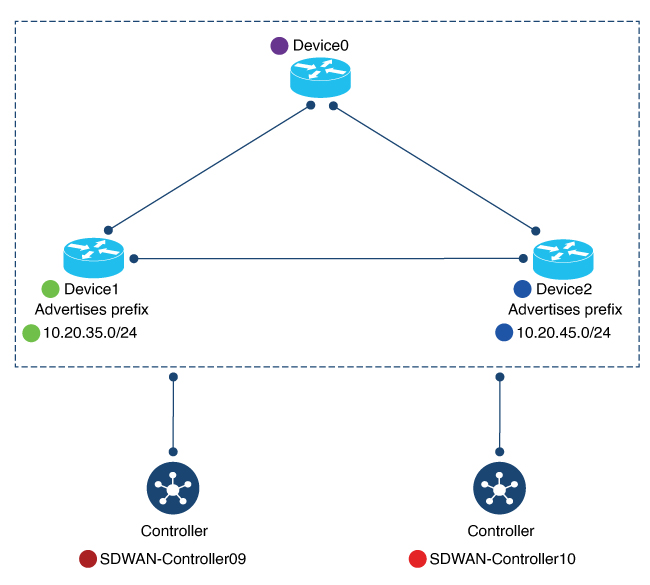
The following figure shows the initial state of the network, with full-mesh connectivity before configuring hub-and-spoke.

Figure 1. Before: Full-Mesh Connectivity

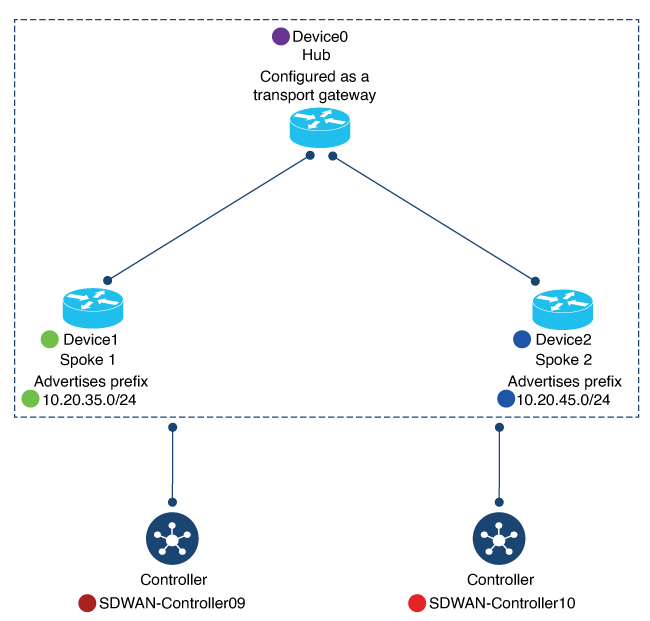
The following figure shows the network connectivity after configuring hub-and-spoke.

Figure 2. After: Hub-and-Spoke Connectivity

Device0 (Hub) Before and After

This section shows the connectivity for Device0 (hub) before and after configuring hub-and-spoke. It includes information about:

  • BFD sessions

  • OMP routes

  • IP routes

BFD Sessions

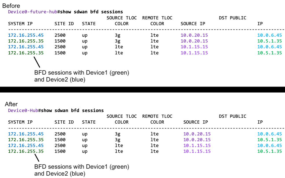
Before configuring hub-and-spoke, on Device0 (future hub), the show sdwan bfd sessions command shows that it has BFD sessions with both Device1 (Spoke1) and Device2 (Spoke1).

After configuring hub-and-spoke, Device0 (hub) retains the same BFD sessions with both Device1 (Spoke1) and Device2 (Spoke2).

Figure 3. Hub: BFD Sessions Before and After
OMP Routes

Before configuring hub-and-spoke, on Device0 (future hub), the show sdwan omp route vpn 1 command shows that the prefixes advertised by Device1 (Spoke1) and Device2 (Spoke2) are reachable only through Device1 (Spoke1) and Device2 (Spoke2), respectively.

After configuring hub-and-spoke on Device0 (hub), the Device1 (Spoke1) prefix and the Device2 (Spoke2) prefix are reachable through the hub itself (FROM PEER column shows 0.0.0.0).

Figure 4. Hub: OMP Routes Before and After
IP Routes

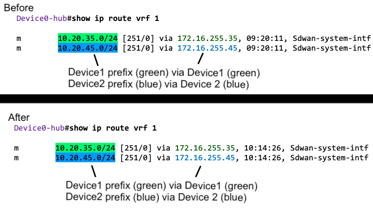
Before configuring hub-and-spoke, on Device0 (future hub), the show ip route vrf 1 command shows that the prefixes advertised by Device1 (Spoke1) and Device2 (Spoke2) are reachable through Device1 (Spoke1) and Device2 (Spoke2), respectively.

After configuring hub-and-spoke, for Device0 (hub), this remains the same.

Figure 5. Hub: IP Routes Before and After

Device1 (Spoke1) Before and After

This section shows the connectivity for Device1 (Spoke1) before and after configuring hub-and-spoke. It includes information about:

  • BFD sessions

  • OMP routes

  • IP routes

BFD Sessions

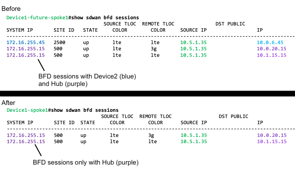
Before configuring hub-and-spoke, on Device1 (future Spoke1), the show sdwan bfd sessions command shows BFD sessions with both Device0 (future hub) and Device2 (future Spoke2).

After configuring hub-and-spoke, Device1 (Spoke1) has only BFD sessions with the hub, not with other spokes—no BFD session with Spoke2 in this example.

Figure 6. Spoke1: BFD Sessions Before and After
OMP Routes

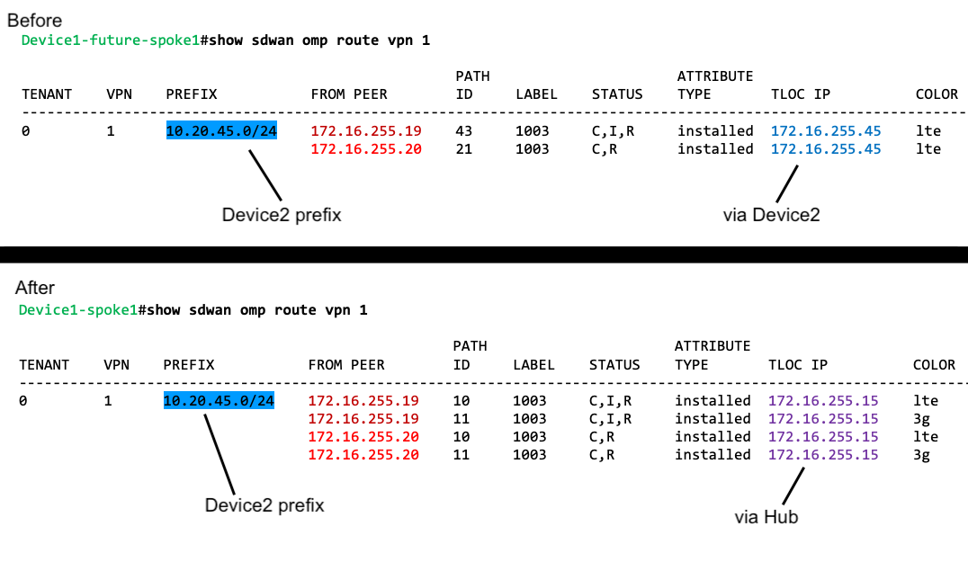
Before configuring hub-and-spoke, on Device1 (future Spoke1), the show sdwan omp route vpn 1 command shows that it can reach the Device2 (Spoke2) prefix directly through Device2. This is evident because the TLOC IP column shows the system IP of Device2.

After configuring hub-and-spoke, Device1 (Spoke1) can reach the Device2 (Spoke2) prefix only through the hub.

Figure 7. Spoke1: OMP Routes Before and After
IP Routes

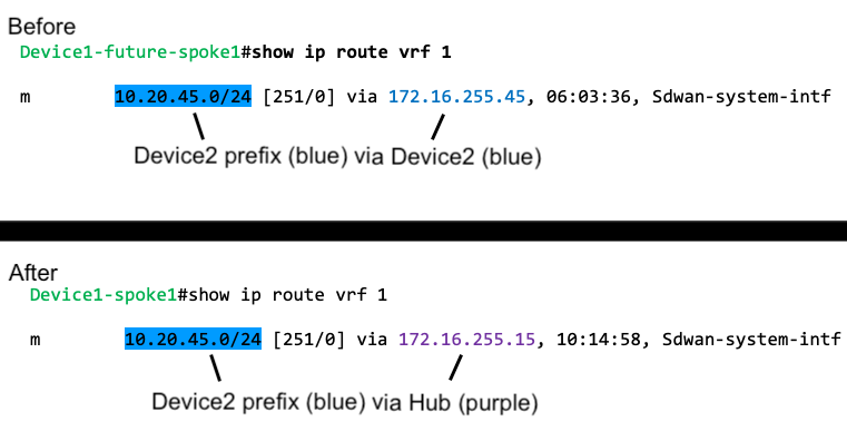
Before configuring hub-and-spoke, on Device1 (future Spoke1), the show ip route vrf 1 command shows that it can reach the Device2 prefix directly through Device2.

After configuring hub-and-spoke, Device1 (Spoke1) can reach the Device2 (Spoke2) prefix only through the hub.

Figure 8. Spoke1: IP Routes Before and After

Device2 (Spoke2) Before and After

This section shows the connectivity for Device2 (Spoke2) before and after configuring hub-and-spoke. It includes information about:

  • BFD sessions

  • OMP routes

  • IP routes

The changes for Device2 before and after configuring hub-and-spoke mostly mirror the changes for Device1.

BFD Sessions

Before configuring hub-and-spoke, on Device2 (future Spoke2), the show sdwan bfd sessions command shows BFD sessions with both Device0 (future hub) and Device1 (future Spoke1).

After configuring hub-and-spoke, Device2 (Spoke2) has only BFD sessions with the hub, not with other spokes—no BFD session with Spoke1 in this example.

Figure 9. Spoke2: BFD Sessions Before and After
OMP Routes

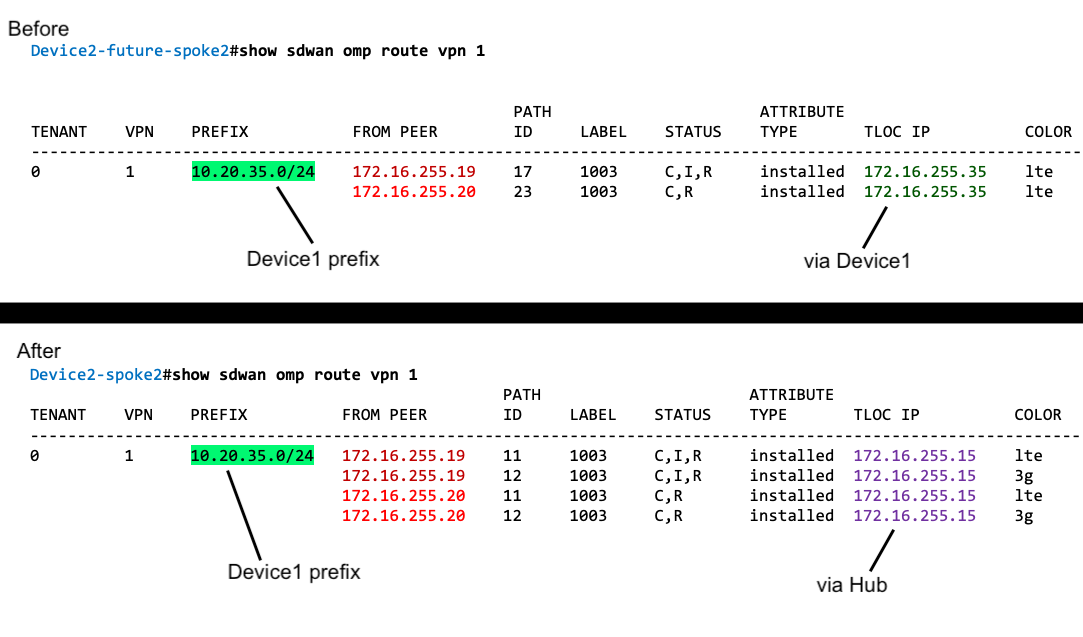
Before configuring hub-and-spoke, on Device2 (future Spoke2), the show sdwan omp route vpn 1 command shows that it can reach the Device1 (Spoke1) prefix directly through Device1. This is evident because the TLOC IP column shows the system IP of Device1.

After configuring hub-and-spoke, Device2 (Spoke2) can reach the Device1 (Spoke1) prefix only through the hub.

Figure 10. Spoke2: OMP Routes Before and After
IP Routes

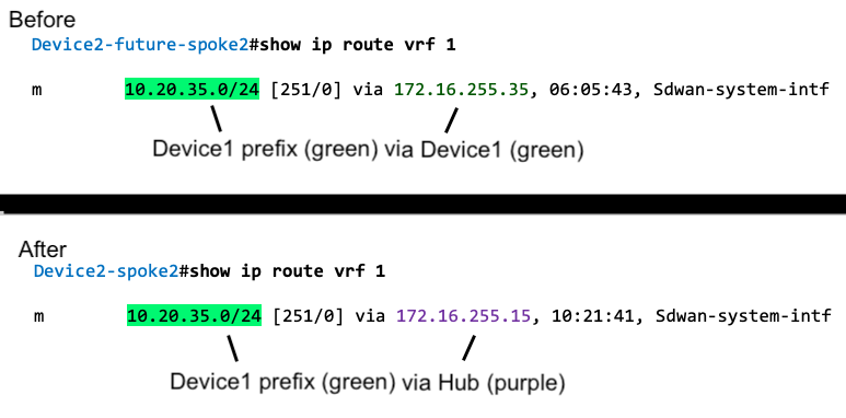
Before configuring hub-and-spoke, on Device2 (future Spoke2), the show ip route vrf 1 command shows that it can reach the Device1 prefix directly through Device1.

After configuring hub-and-spoke, Device2 (Spoke2) can reach the Device1 (Spoke1) prefix only through the hub.

Figure 11. Spoke2: IP Routes Before and After

Benefits of Hub-and-Spoke

A hub-and-spoke topology has many applications and benefits, including the following:

  • Operating each spoke network with a degree of isolation enables applying different policies, transport mechanisms, and so on to each discrete spoke.

  • Reducing the number of peers for the edge routers serving each spoke reduces the resource demands on those edge routers.

  • Routing all inter-spoke traffic through a hub enables you to apply network services, such as firewall policy, to all inter-spoke traffic.

Configuring a hub-and-spoke topology using the process described here simplifies the configuration process, avoiding complex centralized control policy.

Restrictions for Hub-and-Spoke

Restriction

Description

Transport gateway site type

When using a transport gateway as a hub, do not configure its site type as spoke.

On-demand tunnels

In a hub-and-spoke topology, on-demand tunnels are not supported. This is because spoke-to-spoke direct tunnels are not supported in the hub-and-spoke topology.

Migration

There is no automatic procedure for migrating from a hub-and-spoke topology defined by control policy to the hub-and-spoke configuration method described here.

Use Cases for Hub-and-Spoke

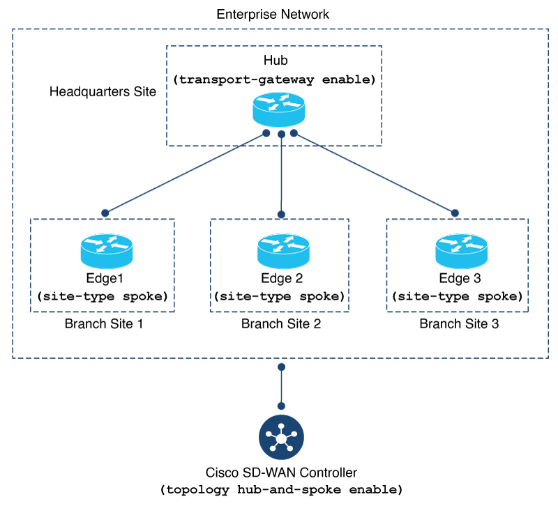
In this use case, an organization’s network includes the following elements:

  • A single device at the organization’s headquarters site that runs numerous network services, such as an enterprise firewall. Network administrators have chosen to designate this as a hub device.

  • Three branch sites, each with an edge router serving the site.

Network administrators have chosen to configure a hub-and-spoke topology to route all traffic flowing between branch sites through the hub at the headquarters site. This enables them to apply the centralized network services to all traffic between branch sites.

They configure a hub-and-spoke topology as shown in the following illustration:

Figure 12. Hub-and-Spoke Topology

Configure a Hub-and-Spoke Topology

The sections that follow describe procedures for configuring a hub-and-spoke topology using transport gateways.

Configure a Cisco Catalyst SD-WAN Controller to Enable Hub-and-Spoke Using Cisco SD-WAN Manager

  1. From the Cisco SD-WAN Manager menu, choose Configuration > Templates.

  2. Click Feature Templates.

  3. Do one of the following:

    • To create a new System template for Cisco SD-WAN Controllers, click Add Template, choose Controller, and click System.

    • To edit an existing Cisco SD-WAN Controller System template, locate a template of type Controller System in the table of existing feature templates, click adjacent to the template, and choose Edit.

  4. In the Topology field, choose Hub and Spoke.

  5. Click Save if creating a new template, or Update if editing an existing template.

Configure a Cisco SD-WAN Controller to Enable Hub-and-Spoke Using a CLI Template

For more information about using CLI templates, see CLI Add-On Feature Templates and CLI Templates. By default, CLI templates execute commands in global configuration mode.

  1. Enter system configuration mode.

    system
  2. Enable a hub-and-spoke topology.

    topology hub-and-spoke enable

    Note


    To disable hub-and-spoke functionality, use the no form of the command.


Example

system
  topology hub-and-spoke enable

Verify a Hub-and-Spoke Configuration

Hub-and-spoke configuration makes use of transport gateways and the site type parameter, which are described in the transport gateway documentation.

Verify that a Cisco Catalyst SD-WAN Controller Has Enabled Hub-and-Spoke Configuration

To verify that a Cisco SD-WAN Controller configuration includes the topology hub-and-spoke enable command, use the show running-config command.

In the following example, the Cisco SD-WAN Controller is configured to enable a hub-and-spoke topology.

sdwanController# show running-config
...
system
 topology hub-and-spoke
  enable

To verify that the topology hub-and-spoke enable command has taken effect, use the show omp summary command. The output indicates the topology. In the following example, the topology is hub-and-spoke.

sdwanController# show omp summary
per-state UP
admin-state UP
...
topology hub-and-spoke