Cloud OnRamp Overview

Cloud OnRamp for IaaS

Cloud OnRamp for IaaS extends the fabric of the Cisco SD-WAN overlay network into public clouds, allowing branches with Cisco CSR1000V Cloud Services routers to connect directly to public-cloud application providers. By eliminating the need for a physical data center, Cloud OnRamp for IaaS improves the performance of IaaS applications.

The connection between the overlay network and a public-cloud application is provided by two or four pairs of redundant Cisco CSR 1000V routers for AWS, which act together as a transit between the overlay network and the application. By using redundant routers to form the transit offers path resiliency to the public cloud. In addition, having redundant routers improves the availability of public-cloud applications. Together, the two routers can remediate in the event of link degradation. You create these routers as part of the Cloud OnRamp workflow.

Cloud OnRamp for IaaS discovers any already existing private cloud instances in geographical cloud regions and allows you to select which of them to make available for the overlay network. In such a scenario, Cloud OnRamp for IaaS allows simple integration between legacy public-cloud connections and the Cisco SD-WAN overlay network.

You configure and manage Cloud OnRamp for IaaS through the vManage NMS server. A configuration wizard in the vManage NMS automates the bring-up of the transit to a your public cloud account and automates the connections between public-cloud applications and the users of those applications at branches in the overlay network.

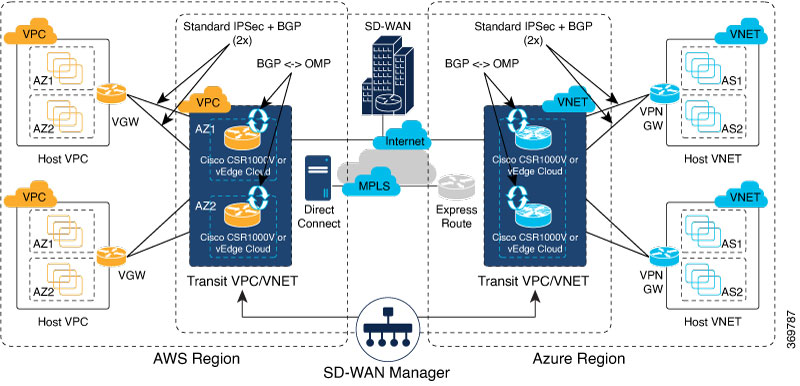
The Cloud OnRamp for IaaS works in conjunction with AWS virtual private clouds (VPCs) and Azure virtual networks (VNets). The following image provides a high level overview of multi-cloud onRamp for IaaS.

Supported Routers

Cloud OnRamp for IaaS is supported on Cisco Cloud vEdge and Cisco Cloud Services Routers (CSRs). In this topic, supported routers are referred to collectively as cloud routers.

Provision vManage for Cloud OnRamp for IaaS

Before you configure Cloud OnRamp for IaaS, ensure that you provision the vManage NMS, AWS, and Azure.

vManage NMS Prerequisites

Before you can configure Cloud OnRamp for IaaS, you must properly provision the vManage NMS.

  • Ensure that your vManage server has access to the internet and that it has a DNS server configured so that it can reach AWS. To configure a DNS server, in the vManage VPN feature configuration template, enter the IP address of a DNS server, and then reattach the configuration template to the vManage server.

  • Ensure that two cloud routers that are to be used to bring up the Cloud OnRamp for IaaS have been added to the vManage NMS and have been attached to the appropriate configuration template. (These two routers are deployed in AWS in their own VPC, and together they form the transit VPC, which is the bridge between the overlay network and AWS cloud applications.) Ensure that the configuration for these routers includes the following:

    • Hostname

    • IP address of vBond orchestrator

    • Site ID

    • Organization name

    • Tunnel interface configuration on the eth1 interface

  • Ensure that the vManage NMS is synchronized with the current time. To check the current time, click the Help (?) icon in the top bar of any vManage screen. The Timestamp field shows the current time. If the time is not correct, configure the vManage server’s time to point to an NTP time server, such as the Google NTP server. To do this, in the vManage NTP feature configuration template, enter the hostname of an NTP server, and then reattach the configuration template to the vManage server. The Google NTP servers are time.google.com, time2.google.com, time3.google.com, and time4.google.com

AWS Prerequisites

Before you can configure Cloud OnRamp for IaaS, ensure that you provision AWS properly.

  • Ensure that you have subscribed to the Viptela marketplace Amazon machine images (AMIs) and the Cisco CSR AMIs in your AWS account. See Subscribe to Cisco SD-WAN AMIs.

  • Ensure that at least one user who has administrative privileges has the AWS API keys for your AWS account. For Cloud OnRamp for IaaS, these keys are used to authenticate the vManage server with AWS and to bring up the VPC and Elastic Compute Cloud (EC2) instances.

  • Check the AWS limits associated with your account (in the Trusted Advisor section of AWS) to ensure that the following resources can be created in your account:

    • 1 VPC, which is required for creating the transit VPC

    • 6 Elastic IP addresses associated with each pair of transit Cisco CSR 1000V routers

    • 1 AWS virtual transit (VGW) for each host VPC

    • 4 VPN connections for mapping each host VPC


      Note

      Cisco IOS XE SD-WAN devices use VRFs in place of VPNs. When you complete the VPN configuration, the system automatically maps the VPN configurations to VRF configurations.


Note

Cisco CSR 1000V support C3 and C4 compute-intensive families.


Subscribe to Cisco SD-WAN AMIs

To use the Cloud OnRamp for IaaS and other Cisco SD-WAN services, you must subscribe to the Amazon Machine Image (AMI) for your router in AWS. When you subscribe, you can complete the following tasks:

  • Launch a cloud router AMI instance

  • Generate a key pair to use for the instance

  • Use the key pair to subscribe to the cloud router instance.

You subscribe to the Cisco CSR 1000V AMI only once, when you first create a Viptela AMI instance.

To create a new AMI subscription and generate a key pair:

  1. In AWS, search to locate a cloud router AMI for your devices.

  2. Select and launch an EC2 instance with the AMI instance. For more information, see Create Cisco IOS XE SD-WAN Cloud VM Instance on AWS.

  3. Generate a key pair. For full instructions, see Set Up the Cisco SD-WAN Cloud VM Instance.

  4. Click Download Key Pair. The key pair then downloads to your local computer as a .pem file.

  5. Click Launch Instance. A failure message displays, because you now need to upload the key pair to complete the subscription process.

To upload the key pair:

  1. In AWS Marketplace, search for your router AMI.

  2. Click Continue.

  3. Click Key Pair to bring up a Cisco CSR 1000V router instance. In the option to enter the key pair, upload the .pem file from your local computer. This is the file that you had generated in Step 3 when creating a new AMI subscription.

Azure Prerequisites

Before you can configure Cloud OnRamp for IaaS, you must properly provision Azure.

  • Ensure that you have accepted the terms and conditions for the Cisco CSR 1000V Router in the Azure Marketplace. See Accept the Azure Terms of Service

  • Ensure that you create an App Registration in Azure and retrieve the credentials for your Azure account. For Cloud OnRamp for IaaS, these credentials are used to authenticate the vManage server with Azure and bring up the VNet and the Virtual Machine instances. See Create and Retrieve Azure Credentials.

  • Check the Azure limits associated with your account (by going to your subscription in the portal and checking Usage + Quotas) to ensure that the following resources can be created in your account:

    • 1 VNet, which is required for creating the transit VNet

    • 1 Availability set, required for Virtual Machine distribution in the transit VNet

    • 6 Static Public IP addresses associated with the transit cloud routers

    • 1 Azure Virtual Network Gateway and 2 Static Public IP Addresses for each host VNet

    • 4 VPN connections for mapping each host VNet


      Note

      Cisco IOS XE SD-WAN devices use VRFs in place of VPNs. When you complete the VPN configurations, the system automatically maps the VPN configurations to VRF configurations.


  • F-series VMs (F4 and F8) are supported on the cloud routers.

Accept the Azure Terms of Service

To use a Cisco cloud router as part of the Cloud OnRamp workflow, you must accept marketplace terms for using a virtual machine (VM). You can do this in one of the following ways:

  • Spin up the cloud router on the portal manually, and accept the terms as part of the final page of the bringup wizard.

  • In the Azure APIs or Powershell/Cloud Shell, use the Set-AzureRmMarketplaceTerms command.

Create and Retrieve Azure Credentials

To create and retrieve Azure credentials, you must create an App Registration in Azure with Contributor privileges:

  1. Launch the Microsoft Azure portal.

  2. Create an application ID:

    1. In the left pane of the Azure portal, click Azure Active Directory.

    2. In the sub-menu, click App registrations.

    3. Click New application registration. The system displays the Create screen.

    4. In the Name field, enter a descriptive name such as CloudOnRampApp.

    5. In the Application Type field, select Web app / API

    6. In the Sign-on URL field, enter any valid sign-on URL; this URL is not used in Cloud OnRamp.

    7. Click Create. The system displays a summary screen with the Application ID.

  3. Create a secret key for the Cloud OnRamp application:

    1. In the summary screen, click Settings in the upper-left corner.

    2. In the right pane, click Keys. The system displays the Keys > Password screen.

    3. On the Passwords screen:

      1. In the Description column, enter a description for your secret key.

      2. In the Expires column, from the Duration drop-down, select the duration for your secret key.

      3. Click Save in the upper-left corner of the screen. The system displays the secret key in the Value column but then hides it permanently, so be sure to copy and save the password in a separate location.

  4. In the left pane of the Azure portal, click Subscriptions to view the subscription ID. If you have multiple subscriptions, copy and save the subscription ID which you are planning to use for configuring the Cloud OnRamp application.

  5. View the Tenant ID:

    1. In the left pane of the Azure portal, click Azure Active Directory.

    2. Click Properties. The system displays the directory ID which is equivalent to the tenant ID.

  6. Assign Contributor privileges to the application:

    1. In the left pane of the Azure portal, click Subscriptions.

    2. Click the subscription that you will be using for the Cloud OnRamp application.

    3. In the subscription pane, navigate to Access Control (IAM).

    4. Click Add. The system displays the Add Permissions screen.

    5. From the Role drop-down menu, select Contributor.

    6. From the Assign Access To drop-down, select the default value Azure AD user, group, or application.

    7. From the Select drop-down, select the application you just created for Cloud OnRamp.

    8. Click Save.

You can now log into the Cloud OnRamp application with the Azure credentials you just created and saved.

Configure Cloud OnRamp for IaaS for AWS

Configure Cloud OnRamp for IaaS for AWS

To configure Cloud OnRamp for IaaS for AWS, you create AWS transit VPCs, each of which consists of up to four pairs of Cisco IOS XE SD-WAN devices. You then map the transit virtual private clouds (VPC)s to host VPCs that already exist in the AWS cloud.

  • Transit VPCs provide the connection between the Cisco overlay network and the cloud-based applications running on host VPCs. Each transit VPC consists of up to four pairs of cloud routers that reside in their own VPC. Multiple routers are used to provide redundancy for the connection between the overlay network and cloud-based applications. On each of these two cloud routers, the transport VPN (VPN 0) connects to a branch router, and the service-side VPNs (any VPN except for VPN 0 and VPN 512) connect to applications and application providers in the public cloud.

  • Cloud OnRamp supports auto-scale for AWS. To use auto-scale, ensure that you associate two to four pairs of cloud routers to a transit VPC. Each of the devices that are associated with the transit VPC for auto-scale should have a device template attached to it.

  • Host VPCs are virtual private clouds in which your cloud-based applications reside. When a transit VPC connects to an application or application provider, it is simply connecting to a host VPC.

  • All host VPCs can belong to the same account, or each host VPC can belong to a different account. A host that belongs one account can be mapped to a transit VPC that belongs to a completely different account. You configure cloud instances by using a configuration wizard.

  1. In vManage NMS, select the Configuration > Cloud onRamp for IaaS screen.

  2. Click Add New Cloud Instance.

  3. In the Add Cloud Instance – log in to a Cloud Server popup:

    1. In the Cloud drop-down, select the Amazon Web Services radio button.

    2. Click IAM Role or Key to log in to the cloud server. It is recommended that you use IAM Role.

    3. If you select IAM Role:

      1. In the Role ARN field, enter the role ARN of the IAM role.

      2. In the External ID field, enter external ID created for the role ARN. It is recommended that the external ID include 10 to 20 characters in random order. To authenticate to the vManage NMS using an IAM role, vManage NMS must be hosted by Cisco on AWS and have the following attributes:

        • Trusts the AWS account, 200235630647, that hosts the vManage NMS.

        • Have all permissions for EC2 and VPC resources.

        • A default timeout of at least one hour.

        If vManage NMS is not hosted by Cisco on AWS, assign an IAM role with permissions to AssumeRole to the vManage server running the Cloud OnRamp process. Refer to the AWS documentation for details.

    4. If you select Key:

      1. In the API Key field, enter your Amazon API key.

      2. In the Secret Key field, enter the password associated with the API key.

  4. Click Login to log in to the cloud server.

    The cloud instance configuration wizard opens. This wizard consists of three screens that you use to select a region and discover host VPCs, add transit VPC, and map host VPCs to transit VPCs. A graphic on the right side of each wizard screen illustrates the steps in the cloud instance configuration process. The steps that are not yet completed are shown in light gray. The current step is highlighted within a blue box. Completed steps are indicated with a green checkmark and are shown in light orange.

  5. Select a region:

    1. In the Choose Region drop-down, choose a geographical region.

    2. Click Save and Finish to create a transit VPC or optionally click Proceed to Discovery and Mapping to continue with the wizard.

  6. Add a transit VPC:

    1. In the Transit VPC Name field, type a name for the transit VPC.

      The name can be up to 128 characters and can contain only uppercase and lowercase letters, the digits 0 through 9, hyphens (–), and underscores (_). It cannot contain spaces or any other characters.

    2. Under Device Information, enter information about the transit VPC:

      1. In the WAN Edge Version drop-down, select the software version of the cloud router to run on the transit VPC.

      2. In the Size of Transit WAN Edge drop-down, choose how much memory and how many CPUs to use for each of the cloud routers that run on the transit VPC.

      3. In the Max. Host VPCs per Device Pair field, select the maximum number of host VPCs that can be mapped to each device pair for the transit VPC. Valid values are 1 through 32.

      4. In the Device Pair 1# fields, select the serial numbers of each device in the pair. To remove a device serial number, click the X that appears in a field.

        The devices that appear in this field have been associated with a configuration template and support the WAN Edge Version that you selected.

      5. To add additional device pairs, click .

        To remove a device pair, click .

        A transit VPC can be associated with one to four device pairs. To enable the Cloud onRamp auto-scale feature for AWS, you must associate at least two device pairs with the transit VPC.

      6. Click Save and Finish to complete the transit VPC configuration or optionally click Proceed to Discovery and Mapping to continue with the wizard.

      7. Click Advanced if you wish to enter more specific configuration options:

        1. In the Transit VPC CIDR field, enter a custom CIDR that has a network mask in the range of 16 to 25. If you choose to leave this field empty, the Transit VPC is created with a default CIDR of 10.0.0.0/16.

        2. In the SSH PEM Key drop-down, select a PEM key pair to log in to an instance. Note that the key pairs are region-specific. Refer to the AWS documentation for instructions on creating key pairs.

      8. Click Save and Finish to complete the transit VPC configuration, or optionally click Proceed to Discovery and Mapping to continue with the wizard.

      9. Select hosts to discover:

        1. In the Select an account to discover field, select a host to map to this transit VPC.

        2. Click Discover Host VPCs.

        3. In the table that displays, choose one or more hosts to map to this transit VPC.

          You can use the search field and options to display only host VPCs that mention specific search criteria.

          You can click the Refresh icon to update the table with current information.

          You can click the Show Table Columns icon to specify which columns display in the table.

        4. Click Next.

  7. Map the host VPCs to transit VPCs:

    1. In the table of host VPCs, select the desired host VPCs.

    2. Click Map VPCs. The Map Host VPCs popup opens.

    3. In the Transit VPC drop-down, select the transit VPC to map to the host VPCs.

    4. In the VPN drop-down, select the VPN in the overlay network in which to place the mapping.

    5. Enable the Route Propagation option if you want vManage to automatically propagate routes to the host VPC routes table.

    6. Click Map VPCs.

    7. Click Save and Complete.

In the VPN feature configuration template for VPN 0, when configuring the two cloud routers that form the transit VPC, ensure that the color you assign to the tunnel interface is a public color, not a private color. Public colors are 3g, biz-internet, blue, bronze, custom1, custom2, custom3, default, gold, green, lte, metro-ethernet, mpls, public-internet, red, and silver.

Display Host VPCs

  1. In the Cloud OnRamp Dashboard, click the pane for the desired VPC. The Host VPCs/Transit VPCs screen opens, and Host VPCs is selected by default. In the bar below this, Mapped Host VPCs is selected by default, and the table on the screen lists the mapping between host and transit VPCs, the state of the transit VPC, and the VPN ID.

  2. To list unmapped host VPCs, click Unmapped Host VPCs. Then click Discover Host VPCs.

  3. To display the transit VPCs, click Transit VPCs.

Map Host VPCs to a Transit VPC

  1. In the Cloud OnRamp Dashboard, click the pane for the desired VPC. The Host VPCs/Transit VPCs screen opens.

  2. Click Un-Mapped Host VPCs.

  3. Click Discover Host VPCs.

  4. From the list of discovered host VPCs, select the desired host VPCs

  5. Click Map VPCs. The Map Host VPCs popup opens.

  6. In the Transit VPC drop-down, choose the desired transit VPC.

  7. In the VPN drop-down, choose the VPN in the overlay network in which to place the mapping.

  8. Click Map VPCs.

Unmap Host VPCs

  1. In the Cloud OnRamp Dashboard, click the pane for the desired VPC. The Host VPCs/Transit VPCs screen opens.

  2. Click Mapped Host VPCs.

  3. From the list of VPCs, select the desired host VPCs.

  4. Click Unmap VPCs.

  5. Click OK to confirm the unmapping.

Unmapping host VPCs deletes all VPN connections to the VPN gateway in the host VPC, and then deletes the VPN gateway. When you make additional VPN connections to a mapped host VPC, they will be terminated as part of the unmapping process.

Display Transit VPCs

  1. In the Cloud OnRamp Dashboard, click the pane for the desired VPC. The Host VPCs/Transit VPCs screen opens, and Host VPCs is selected by default.

  2. Click Transit VPCs.

The table at the bottom of the screen lists the transit VPCs.

Add Transit VPC

  1. In the Cloud OnRamp Dashboard, click the pane for the desired VPC. The Host VPCs/Transit VPCs screen opens, and Host VPCs is selected by default.

  2. Click Transit VPCs.

  3. Click Add Transit VPC.

    To add a transit VPC, perform operations from step 6 of Configure Cloud OnRamp for IaaS for AWS.

Delete Device Pair

The device pair must be offline.

  1. In the Cloud OnRamp Dashboard,

  2. Click a device pair ID.

  3. Verify that the status of the device pair is offline.

  4. To descale the device pairs, click the trash can icon in the Action column or click the Trigger Autoscale option.

Delete Transit VPC

Prerequisite: Delete the device pairs that are associated with the transit VPC.


Note

To delete the last pair of online device pairs, you must delete a transit VPC.


  1. In the Cloud OnRamp Dashboard, click the pane for the desired VPC. The Host VPCs/Transit VPCs screen opens, and Host VPCs is selected by default.

  2. Click Host VPCs.

  3. Select all host VPCs, and click Unmap VPCs.

    Ensure that all host mappings with transit VPCs are unmapped.

  4. Click OK to confirm the unmapping.

  5. Click Transit VPCs.

  6. Click the trash icon to the left of the row for the transit VPC.


    Note

    The trash icon is not available for the last device pair of transit VPC. Hence, to delete the last device pair, click Delete Transit drop-down list at the right corner. The trash icon is only available from the second device pair onwards.


  7. Click OK to confirm.

Add Device Pairs

  1. Click Add Device Pair.

    Ensure that the devices you are adding are already associated with a device template.

  2. In the box, select a device pair.

  3. Click the Add icon to add more device pairs.

    You can add up to a total of four device pairs to the transit VPC.

  4. Click Save.

History of Device Pairs for Transit VPCs

To display the Transit VPC Connection History page with all its corresponding events, click History for a device pair.

In this view, by default, a histogram of events that have occurred in the previous one hour is displayed and a table of all events for the selected transit VPC. The table lists all the events generated in the transit VPC. The events can be one of the following:

  • Device Pair Added

  • Device Pair Spun Up

  • Device Pair Spun Down

  • Device Pair Removed

  • Host Vpc Mapped

  • Host Vpc Unmapped

  • Host Vpc Moved

  • Transit Vpc Created

  • Transit Vpc Removed

Edit Transit VPC

You can change the maximum number of host VPCs that can be mapped to a device pair.

  1. Click Edit Transit Details. Provide a value for the maximum number of host VPCs per device pair to which the transit VPC can be mapped.

  2. Click OK.

This operation can trigger auto-scale.

Configure Cloud OnRamp for IaaS for Azure

To configure Cloud OnRamp for IaaS for Azure, you create Azure transit VNets, each of which consist of a pair of routers. You then map the host vNets to transit VNets that already exist in the Azure cloud. All VNets reside in the same resource group.

  • Transit VNets provide the connection between the overlay network and the cloud-based applications running on host VNet. Each transit VNet consists of two routers that reside in their own VNet. Two routers are used to provide redundancy for the connection between the overlay network and cloud-based applications. On each of these two cloud routers, the transport VPN (VPN 0) connects to a branch router, and the service-side VPNs (any VPN except for VPN 0 and VPN 512) connect to applications and application providers in the public cloud.

  • Host VNets are virtual private clouds in which your cloud-based applications reside. When a transit VNet connects to an application or application provider, it is simply connecting to a host VNet.

In the Cloud OnRamp configuration process, you map one or more host VPCs or host VNets to a single transit VPC or transit VNet. In doing this, you are configuring the cloud-based applications that branch users are able to access.

The mapping process establishes IPsec and BGP connections between the transit VPC or transit VNet and each host VPC or host VNet. The IPsec tunnel that connects the transit and host VPC or VNet runs IKE to provide security for the connection. For AWS, the IPsec tunnel runs IKE Version 1. For Azure, the IPsec tunnel runs IKE version 2. The BGP connection that is established over the secure IPsec tunnel allows the transit and host VPC or VNet to exchange routes so that the transit VPC or VNet can direct traffic from the branch to the proper host VPC or VNet, and hence to the proper cloud-based application.

During the mapping process, the IPsec tunnels and BGP peering sessions are configured and established automatically. After you establish the mappings, you can view the IPsec and BGP configurations, in the VPN Interface IPsec and BGP feature configuration templates, respectively, and you can modify them as necessary. You can configure Cloud OnRamp for IaaS for Azure by using the configuration wizard:

Create a Cloud Instance

  1. In vManage NMS, select the Configuration > Cloud onRamp for IaaS screen.

  2. Click Add New Cloud Instance:
  3. In the Add Cloud Instance–Log In to a Cloud Server popup:

    1. In the Cloud drop-down, select Azure as the cloud type.

    2. To give vManage programmatic access to your Azure Subscription, log in to the cloud server:

      1. In the Subscription ID field, enter the ID of the Azure subscription you want to use as part of the Cloud OnRamp workflow.

      2. In the Client ID field, enter the ID of an existing application or create a new application in Azure. To create a new application, go to your Azure Active Directory > App Registrations > New Application Registration.

      3. In the Tenant ID field, enter the ID of your Azure account. To find the tenant ID, go to your Azure Active Directory and click Properties.

      4. In the Secret Key field, enter the password associated with the client ID.

  4. Click Log In. The cloud instance configuration wizard opens.

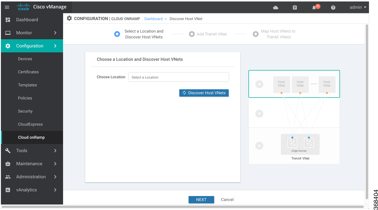
    This wizard consists of three screens that you use to select a location and discover host VNets, add transit VNet, and map host VNets to transit VNets. A graphic on the right side of each wizard screen illustrates the steps in the cloud instance configuration process. Steps not yet completed are shown in light gray. The current step is highlighted within a blue box. Completed steps are indicated with a green checkmark and are shown in light orange.

  5. Select a location and discover host VNets:

    1. In the Choose Location drop-down, select a geographical location.

    2. Click Save and Finish to create a transit VNet or optionally click Proceed to Discovery and Mapping to continue with the wizard.

  6. Add a transit VNet:

    1. In the Transit VNet Name field, type a name for the transit VNet.

      The name can be up to 32 characters and can contain only uppercase and lowercase letters, the digits 0 through 9, hyphens (–), and underscores (_). It cannot contain spaces or any other characters.

    2. Under Device Information, enter information about the transit VNet:

      1. In the WAN Edge Version drop-down, select the software version to run on the VNet transit. The drop-down lists the published versions of the Viptela software in the Azure marketplace.

      2. In the Size of Transit VNet drop-down, select how much memory and how many CPUs to create on the VNet transit.

      3. In the Device 1 drop-down, select the serial number to use.

      4. In the Device 2 drop-down, select the serial number to use.

      5. To add additional device pairs, click .

        To remove a device pair, click .

      6. Click Save and Finish to complete the transit VNet configuration or optionally click Proceed to Discovery and Mapping to continue with the wizard.

      7. Click Advanced if you wish to enter more specific configuration options.

      8. In the Transit VNet CIDR field, enter a custom CIDR that has a network mask in the range of 16 to 25. If you choose to leave this field empty, the Transit VPC is created with a default CIDR of 10.0.0.0/16.

    3. Click Save and Finish to complete the transit VPC configuration, or optionally click Proceed to Discovery and Mapping to continue with the wizard.

  7. Map the host VNets to transit VNets:

    1. In the table of host VNets, select the desired host VNet.

    2. Click Map VNets. The Map Host VNets popup opens.

    3. In the Transit VNet drop-down, choose the transit VNet to map to the host VNets.

    4. In the VPN drop-down, choose the VPN in the overlay network in which to place the mapping.

    5. In the IPSec Tunnel CIDR section, enter two pairs of interface IP addresses for each Cisco CSR 1000V to configure IPSec tunnels to reach the Azure virtual network transit. The IP addresses must be network addresses in the /30 subnet, be unique across the overlay network, and not be a part of the host VNet CIDR. If they are part of the host VNet CIDR, Azure will return an error while attempting to create VPN connections to the transit VNet.

    6. In the Azure Information section:

      1. In the BGP ASN field, enter the ASN that will be configured on the Azure Virtual Network Gateway that is spun up within the host VNet. Use an ASN that is not part of an existing configuration on Azure. For acceptable ASN values, refer to Azure documentation.

      2. In the Host VNet Gateway Subnet field, enter a host VNet subnet in which the Virtual Network Gateway can reside. It is recommended you use a /28 subnet or higher. You must not provide a subnet that is already created in the VNet.

    7. Click Map VNets.

    8. Click Save and Complete.

In the VPN feature configuration template for VPN 0, when configuring the two cloud routers that form the transit VNet, ensure that the color you assign to the tunnel interface is a public color, not a private color. Public colors are 3g, biz-internet, blue, bronze, custom1, custom2, custom3, default, gold, green, lte, metro-ethernet, mpls, public-internet, red, and silver.

Display Host VNets

  1. In the Cloud OnRamp Dashboard, click the pane for the desired VNet. The Host VNets/Transit VNets screen opens, and Host VNets is selected by default. In the bar below this, Mapped Host VNets is selected by default, and the table on the screen lists the mapping between host and transit VNets, the state of the transit VNet, and the VPN ID.

  2. To list unmapped host VNets, click Unmapped Host VNets.

  3. To display the transit  VNets, click Transit VNets.

Map Host VNets to an Existing Transit VNet

  1. In the Cloud OnRamp Dashboard, click the pane for the desired location of the required account. The Host VNets/Transit VNets screen opens.

  2. Click Unmapped Host VNets.

  3. Click Discover Host VNets.

  4. From the list of discovered host VNets, select the desired host VNet.

  5. Click Map VNets. The Map Host VNets popup opens.

  6. In the Transit VNet drop-down, select the desired transit VNet.

  7. In the VPN drop-down, choose the VPN in the overlay network in which to place the mapping.

  8. Click Map VNets.

Unmap Host VNets

  1. In the Cloud OnRamp Dashboard, click the pane for the desired VNet. The Host VNets/Transit VNets screen opens.

  2. Click Mapped Host VNets.

  3. From the list of VNets, select the desired host VNets. It is recommended that you unmap one vNet at a time. If you want to unmap multiple vNets, do not select more than three in a single unmapping operation.

  4. Click Unmap VNets.

  5. Click OK to confirm the unmapping.

Display Transit VNets

  1. In the Cloud OnRamp Dashboard, click the pane for the desired VNets. The Host VNets/Transit VNets screen opens, and Host VNets is selected by default.

  2. Click Transit VNets.

The table at the bottom of the screen lists the transit VNets.

Add a Transit VNet

  1. In the Cloud OnRamp Dashboard, click the pane for the desired VNet. The Host VNets/Transit VNets screen opens, and Host VNets is selected by default.

  2. Click Transit VNets.

  3. Click Add Transit VNet.

Delete a Transit VNet

  1. In the Cloud OnRamp Dashboard, click the pane for the desired VNet. The Host VNets/Transit VNets screen opens, and Host VNets is selected by default.

  2. Click Mapped Host VNets.

  3. Select the desired host VNet, and click Unmap VNets.

  4. Click OK to confirm the unmapping.

  5. Click Transit VNets.

  6. Click the trash icon to the left of the row for the transit VNet.

  7. Click OK to confirm.

Troubleshoot Cloud OnRamp for IaaS

This section describes how to troubleshoot common problems with Cloud OnRamp for IaaS.

Two Cisco CSR 1000V Routers are Not Available

Problem Statement

In vManage NMS, when you select the Configuration > Cloud OnRamp screen and click Add New Cloud instance, you see an error message indicating that two Cisco CSR 1000V routers are not available.

Resolve the Problem

The vManage NMS does not have two Cisco CSR 1000V routers that are running licensed Cisco SD-WAN software. Contact your operations team so that they can create the necessary Cisco CSR 1000V routers.

If the Cisco CSR 1000V routers are present and the error message persists, the two Cisco CSR 1000V routers are not attached to configuration templates. Attach these templates in the vManage Configuration > Templates Device screen. Select the Cisco CSR 1000V router, and then select Attach Devices from the More Actions icon to the right of the row.

Required Permissions for API

Problem Statement

When you enter your API keys, you get an error message indicating that this user does not have the required permissions.

Resolve the Problem

Ensure that the vManage server can reach the internet and has a DNS server configured so that it can reach AWS or Azure. To configure a DNS server, in the vManage VPN feature configuration template, enter the IP address of a DNS server, and then reattach the configuration template to the vManage server.

For AWS, check the API keys belonging to your AWS account. If you think you have the wrong keys, generate another pair of keys.

For AWS, if you are entering the correct keys and the error message persists, the keys do not have the required permissions. Check the user permissions associated with the key. Give the user the necessary permissions to create and edit VPCs and EC2 instances.

If the error message persists, check the time of the vManage server to ensure that it is set to the current time. If it is not, configure the vManage server’s time to point to the Google NTP server. In the vManage NTP feature configuration template, enter a hostname of time.google.com, time2.google.com, time3.google.com, or time4.google.com. Then reattach the configuration template to the vManage server.

No Cisco CSR 1000V Software Versions Appear in the Drop-Down

Problem Statement

When you are trying to configure transit VPC parameters for the transit VPC, no Cisco CSR 1000V software versions are listed in the drop-down.

Resolve the Problem

Ensure that your customer account has subscribed to the Cisco SD-WAN Cisco CSR 1000V routers.

Ensure that the Cisco CSR 1000V router is running software Release 19.2.0 or later.

No VPNs Appear in Drop-Down

Problem Statement

When you select the host VPCs or VNets to map, no VPNs are listed in the drop-down.

Resolve the Problem

This problem occurs when the device configuration template attached to the cloud router includes no service-side VPNs. Service-side VPNs (VPNs other than VPN 0 and VPN 512) are required to configure the IPsec connection between the two cloud routers selected for the transit and host VPCs or VNets.

This problem can also occur if the two cloud routers selected for the transit VPC or VNet have no overlapping service-side VPNs. Because the two Cisco CSR 1000V routers form and active–active pair, the same service-side VPNs must be configured on both of them.

To configure service-side VPNs, in the vManage VPN feature configuration template, configure at least one service-side VPN. Ensure that at least one of the service-side VPNs is the same on both routers. Then reattach the configuration template to the routers.

Cloud OnRamp Task Fails

Problem Statement

After you have completed mapping the host VPCs to the transit VPCs, or host VNets to transit VNets, the Cloud OnRamp tasks fails.

Resolve the Problem

Review the displayed task information that is displayed on the screen to determine why the task failed. If the errors are related to AWS or Azure resources, ensure that all required resources are in place.

Cloud OnRamp Task Succeeds, But Routers Are Down

Problem Statement

The Cloud OnRamp task was successful, but the cloud routers are still in the Down state.

Resolve the Problem

Check the configuration templates:

  • Check that all portions of the cloud router configuration, including policies, are valid and correct. If the configuration are invalid, they are not applied to the router, so the router never comes up.

  • Check that the configuration for the vBond orchestrator is correct. If the DNS name or IP address configured of the vBond orchestrator is wrong, the Cisco CSR 1000V router is unable to reach it and hence is unable to join the overlay network.

After you have determined what the configuration issues are:

  1. Delete the Cloud OnRamp components:

    1. Unmap the host VPNs and the transit VPCs or VNets.

    2. Delete the transit Cisco CSR 1000V routers.

  2. Edit the configuration templates and reattach them to the cloud routers.

  3. Repeat the Cloud OnRamp configuration process.

Desired Routes Not Exchanged

Problem Statement

The Cloud OnRamp configuration workflow is successful, the Cisco CSR 1000V routers are up and running, but the desired routes are not getting exchanged.

Resolve the Problem

In vManage NMS, check the BGP configuration on the transit cloud routers. During the mapping process when you configure Cloud OnRamp service, BGP is configured to advertise the network 0.0.0.0/0. Make sure that the service-side VPN contains an IP route that points to 0.0.0.0/0. If necessary, add a static route in the VPN feature configuration template, and then reattach the configuration to the two cloud routers that you selected for the transit VPC or VNet.

On AWS, go to the host VPC and check its route table. In the route table, click the option Enable route propagation to ensure that the VPC receives the routes.

End-to-End Ping Is Unsuccessful

Problem Statement

Routing is working properly, but an end-to-end ping is not working.

Resolve the Problem

On AWS, check the security group rules of the host VPC. The security group rules must allow the source IP address range subnets of the on-premises or branch-side devices, to allow traffic from the branch to reach AWS.

Cloud OnRamp for SaaS

Enterprise software providers deliver many applications as Software as a Service (SaaS) cloud applications, such as Dropbox, Microsoft Office365, and Salesforce. Latency and packet loss impact the performance of these applications, but in legacy networks, network administrators have little visibility into network characteristics between end users and SaaS applications. When a path is impaired in a legacy network, the manual process of shifting application traffic to an alternate path is complex, time consuming, and error prone.

Cloud OnRamp for SaaS (formerly called CloudExpress service) addresses these issues by optimizing performance for SaaS applications in the Cisco SD-WAN overlay network. From a central dashboard, Cloud OnRamp for SaaS provides clear visibility into the performance of individual cloud applications and automatically chooses the best path for each one. It responds to changes in network performance in real-time, intelligently re-routing cloud application traffic onto the best available path. The following image provdes a high level overview of OnRamp for SaaS.

Cloud OnRamp for SaaS calculates a value called the Viptela Quality of Experience (vQoE). The vQoE value weighs loss and latency using a formula customized for each application. For example, email applications tolerate latency better than video applications, and video applications tolerate loss better than email applications. The vQoE value ranges from zero to ten, with zero being the worst quality and ten being the best. Cloud OnRamp for SaaS computes vQoE values for applications and paths, then assigns applications to the paths that best match their vQoE value. Cloud OnRamp for SaaS periodically recalculates vQoE values for paths to ensure ongoing optimal application performance.

Cloud OnRamp for SaaS supports the following enterprise applications:

  • Amazon Web Service (AWS)

  • Box

  • Concur

  • Dropbox

  • Google Apps

  • GoToMeeting

  • Intuit

  • Microsoft Office 365

  • Oracle

  • Salesforce

  • SugarCRM

  • Zendesk

  • Zoho CRM

Cisco IOS XE SD-WAN devices use VRFs in place of VPNs. So, when you complete the configuration, the system automatically maps the VPN configurations to VRF configurations.

Enable Cloud OnRamp for SaaS

You can enable Cloud OnRamp for SaaS in your Cisco SD-WAN overlay network on sites with Direct Internet Access (DIA) and on DIA sites that access the internet through a secure web gateway such as Zscaler or iboss. You can also enable Cloud OnRamp for SaaS on client sites that access the internet through another site in the overlay network, called a gateway site. Gateway sites can include regional data centers or carrier-neutral facilities. When you enable Cloud OnRamp for SaaS on a client site that accesses the internet through a gateway, you also enable Cloud OnRamp for SaaS on the gateway site.

All Cisco SD-WAN devices configured for Cloud OnRamp for SaaS must meet the following requirements:

  • The devices must run Cisco SD-WAN Software Release 16.3 or higher.

  • The devices must run in vManage mode.

  • You must configure a DNS server address in VPN 0.

  • You must configure local exit interfaces in VPN 0:

    • If the local interface list contains only physical interfaces, you must enable NAT on those interfaces. You can use normal default IP routes for next hops.

    • If the local interface list contains only GRE interfaces, you do not need to enable NAT on those interfaces. You can add default routes to the IP address of the GRE tunnel to the destination.

Enable Cloud OnRamp for SaaS

  1. In vManage NMS, click Administration > Settings.

  2. Click the Edit button to the right of the Cloud onRamp for SaaS bar.

  3. In the Cloud onRamp for SaaS field, click Enabled.

  4. Click Save.

Configure Cloud OnRamp for SaaS

Add Applications

  1. In vManage NMS, select the Configuration > Cloud onRamp for SaaS screen. The Cloud OnRamp for SaaS Dashboard screen appears.

    To edit the VPN configured for an application, click the Edit icon for that application, then enter the new VPN. You can enter any VPN other than 0, which is the transport VPN, or 512, which is the management VPN.

  2. To add applications, from the Manage Cloud OnRamp for SaaS drop-down, located to the right of the title bar, select Applications to add applications to the cloud onRamp configuration.

  3. Click the Add Applications and VPN button. The Add Applications & VPN pop-up window appears.

  4. In the Applications field, select an application.

  5. In the VPN field, enter the service VPN in which that application runs. You can enter any VPN other than 0 and 512.

  6. Click Add.

  7. Repeat Steps 3 through 6 for each application you want to add.

  8. Click Save Changes.

Configure Client Sites

To configure Cloud OnRamp for SaaS on client sites that access the internet through gateways, you must configure Cloud OnRamp for SaaS both on the client sites and on the gateway sites.

Client sites in Cloud onRamp service choose the best gateway site for each application to use for accessing the internet.

  1. In vManage NMS, select the Configuration > Cloud onRamp for SaaS screen. The Cloud OnRamp for SaaS Dashboard screen opens.

  2. From the Manage Cloud OnRamp for SaaS drop-down, located to the right of the title bar, select Client Sites. The screen changes and displays the following elements:

    • Attach Sites—Add client sites to Cloud onRamp for SaaS service.

    • Detach Sites—Remove client sites from Cloud onRamp for SaaS service.

    • Client sites table—Display client sites configured for Cloud onRamp for SaaS service.

  3. In the Manage Sites screen, click the Attach Sites button. The Attach Sites screen displays all sites in the overlay network with available sites highlighted. For a site to be available, all devices at that site must be running in vManage mode.

  4. In the Available Sites pane, select a client site to attach and click the right arrow. To remove a site, select it in the Selected Sites pane and click the left arrow.

  5. Click Attach. vManage NMS pushes the feature template configuration to the devices. The Task View window displays a Validation Success message.

  6. Select Configuration > Cloud onRamp for SaaS to return to the Cloud OnRamp for SaaS Dashboard screen.

  7. From the Manage Cloud OnRamp for SaaS drop-down, located to the right of the title bar, choose Gateways. The screen changes and displays the following elements:

    • Attach Gateways—Attach gateway sites.

    • Detach Sites—Remove gateway sites from Cloud onRamp service.

    • Edit Sites—Edit interfaces on gateway sites.

    • Gateways table—Display gateway sites configured for Cloud onRamp service.

  8. In the Manage Gateways screen, click the Attach Gateways button. The Attach Gateways popup window displays all sites in your overlay network with available sites highlighted. For a site to be available, all devices at that site must be running in vManage mode.

  9. In the Available Gateways pane, select a gateway site to attach and click the right arrow. To remove a site, select it in the Selected Sites pane and click the left arrow.

  10. If you do not specify interfaces for Cloud OnRamp for SaaS to use, the system selects a NAT-enabled physical interface from VPN 0. To specify GRE interfaces for Cloud OnRamp for SaaS to use:

    1. Click the link Add interfaces to selected sites (optional), located in the bottom right corner of the window.

    2. In the Select Interfaces drop-down, select GRE interfaces to add.

    3. Click Save Changes.

  11. Click Attach. vManage NMS pushes the feature template configuration to the devices. The Task View window displays a Validation Success message.

  12. To return to the Cloud OnRamp for SaaS Dashboard, select Configuration > Cloud onRamp for SaaS.

To edit Cloud OnRamp for SaaS interfaces on gateway sites:

  1. Select the sites you want to edit and click Edit Gateways.

  2. In the Edit Interfaces of Selected Sites screen, select a site to edit.

    • To add interfaces, click the Interfaces field to select available interfaces.

    • To remove an interface, click the X beside its name.

  3. Click Save Changes to push the new template to the Cisco CSR 1000V routers.

Configure DIA Sites

  1. In vManage NMS, select the Configuration > Cloud onRamp for SaaS screen. The Cloud OnRamp for SaaS Dashboard screen opens.

    In the title bar, choose Manage Cloud OnRamp for SaaS > DIA. The screen changes and displays the following elements:

    • Attach DIA Sites—Attach DIA sites.

    • Detach DIA Sites—Remove DIA sites.

    • Edit DIA Sites—Edit interfaces on DIA sites.

    • Sites table—Display sites configured for Cloud onRamp service.

  2. From the Manage Cloud OnRamp for SaaS drop-down, located to the right of the title bar, choose Direct Internet Access (DIA) Sites.

  3. In the Manage DIA screen, click Attach DIA Sites. The Attach DIA Sites popup window displays all sites in your overlay network with available sites highlighted. For a site to be available, all devices at that site must be running in vManage mode.

  4. In the Available Sites pane, select a site to attach and click the right arrow. To remove a site, select it in the Selected Sites pane and click the left arrow.

  5. If you do not specify interfaces for Cloud OnRamp for SaaS to use, the system will select a NAT-enabled physical interface from VPN 0. If you would like to specify GRE interfaces for Cloud OnRamp for SaaS to use:

    1. Click the link, Add interfaces to selected sites (optional), located in the bottom right corner of the window.

    2. In the Select Interfaces drop-down, choose GRE interfaces to add.

    3. Click Save Changes.

  6. Click Attach. vManage NMS pushes the feature template configuration to the devices. The Task View window displays a Validation Success message.

  7. To return to the Cloud OnRamp for SaaS Dashboard, choose Configuration > Cloud onRamp for SaaS.

To edit Cloud onRamp interfaces on DIA sites:

  1. Select the sites you want to edit and click Edit DIA Sites.

  2. In the Edit Interfaces of Selected Sites screen, select a site to edit.

    • To add interfaces, click the Interfaces field to select available interfaces.

    • To remove an interface, click the X beside its name.

  3. Click Save Changes to push the new template to the Cisco IOS XE SD-WAN device s.

You have now completed configuring the Cloud OnRamp for SaaS. To return to the Cloud OnRamp for SaaS Dashboard, choose the Configuration > Cloud onRamp for SaaS screen.

Monitor Performance of Cloud OnRamp for SaaS

View Application Performance

In vManage NMS, select the Configuration > Cloud OnRamp for SaaS screen. The Cloud OnRamp for SaaS Dashboard displays the performance of each cloud application in a separate pane.

Each application pane displays the number of Cisco IOS XE SD-WAN devices accessing the application and the quality of the connection:

  • The bottom status bar displays green for devices experiencing good quality.

  • The middle status bar displays yellow for devices experiencing average quality.

  • The top status bar displays red for devices experiencing bad quality.

The number to the right of each status bar indicates how many devices are experiencing that quality of connection.

View Application Details

  1. In vManage NMS, choose the Configuration > Cloud OnRamp for SaaS screen. The Cloud OnRamp for SaaS Dashboard displays each cloud application in a separate pane.

  2. Click in an application's pane. vManage NMS displays a list of sites accessing the application.

  3. Click a graph icon in the vQoE Score column to display vQoE history for that site:

    • Click a predefined or custom time period for which to display data.

    • Hover over a point on the chart to display vQoE details for that point in time.

Cloud OnRamp for Colocation Solution Overview

Digitization is placing high demands on IT to increase their speed of services and products that are delivered to customers, partners, and employees, while maintaining a high level of security. The interconnectivity between users and applications is becoming complex digital business architecture. This means network must be fast and flexible to meet the expanding changes and demand. At the same time, users want to increase the speed and reduce complexity of deployment without compromising the security.

A Cloud OnRamp for Colocation is a campus, large branch, or a colocation, where the traffic gets aggregated. This solution is a flexible architecture that securely connects to enterprise applications that are hosted in the enterprise data center, public cloud, private or hybrid cloud to its endpoints such as, employees, devices, customers, or partners. This functionality is achieved by using Cloud Services Platform 5000 (CSP 5444) as the base Network Function Virtualization (NFV) platform that securely connects endpoints of an enterprise to applications. By deploying Cloud OnRamp for Colocation solution in colocation centers, customers can virtualize network services and other applications, and consolidate them into a single platform. The primary goal of the solution is to facilitate secure multicloud connectivity for Enterprise customers.

The Cloud OnRamp for Colocation solution offers the following benefits:

  • Performance—Enterprises can optimize application performance by strategically placing the solution in colocation centers that are closest to the SaaS and public IaaS cloud providers.

  • Agility—By virtualizing network services, enterprises can simplify their operations. Scaling up and down, and adding new services can now be done remotely. The Cisco Network Function Virtualization Infrastructure Software (NFVIS) on CSP 5444 negates the need to order, cable, rack, and stack dedicated hardware appliances when capacity must be increased or changes are required.

  • Security—The centralization of communication patterns between employees, customers, partners, and applications allows for better and more consistent implementation of security policies.

  • Cost savings—By having a central location to connect to various clouds (including private clouds), enterprises can optimize the cost of circuits to connect their users to applications. The circuit costs for a colocation facility are less than in a private data center.

Figure 1. Solution Architectural Overview
The Cisco SD-WAN Network Hub solution architectural overview comprises of several components such as, Network fabric, CSP devices, Virtualization Infrastructure software, virtual network functions, service chaining of VNFs, solution orchestrator.

The Cloud OnRamp for Colocation solution can be deployed in multiple colocations. A colocation is a stack of compute and networking fabric that brings up multiple virtual networking functions and multiple service chains on them. This stack connects branch users, endpoints to a hybrid cloud or data center. vManage is used as the orchestrator to provision the devices in a colocation. Each colocation does not have visibility of other colocations in the same site or across sites.

Manage Clusters

Use the Cloud OnRamp for Colocation screen to configure a Cloud OnRamp for Colocation cluster and service groups that can be used with the cluster.

The three steps to configure Cloud OnRamp for Colocation devices are:

A Cloud OnRamp for Colocation cluster is a collection of two to eight CSP devices and two switches. The supported cluster templates are:

  • Small cluster—2 Catalyst 9500+2 CSP

  • Medium Cluster—2 Catalyst 9500+4 CSP

  • Large Cluster—2 Catalyst 9500+6 CSP

  • X-Large Cluster—2 Catalyst 9500+8 CSP


Note

Ensure that you add a minimum of two CSP devices one-by-one to a cluster. You can keep adding three, four, and so on, up to a maximum of eight CSP devices. You can edit a Day-N configuration of any cluster, and add pairs of CSP devices to each site up to a maximum of eight CSP devices.


Ensure that all devices that you bring into a cluster have the same software version.

Following are the cluster states:

  • Incomplete—When a cluster is created from the vManage interface without providing the minimum requirement of two CSP devices and two switches. Also, cluster activation is not yet triggered.

  • Inactive—When a cluster is created from the vManage interface after providing the minimum requirement of two CSP devices and two Switches, and cluster activation is not yet triggered.

  • Init—When the cluster activation is triggered from the vManage interface and Day-0 configuration push to the end devices is pending.

  • Inprogress—When one of the CSP devices within a cluster comes up with control connections, the cluster moves to this state.

  • Pending—When the Day-0 configuration push is pending or VNF install is pending.

  • Active—When a cluster is activated successfully and NCS has pushed the configuration to the end device.

  • Failure—If Cisco Colo Manager has not been brought up or if any of the CSP devices that failed to receive an UP event.

A cluster transitioning to an active state or failure state is as follows:

  • Inactive > Init > Inprogress > Pending > Active—Success

  • Inactive > Init > Inprogress > Pending > Failure—Failure

Provision and Configure Cluster

This topic describes about activating a cluster that enable deployment of service chains.

To provision and configure a cluster, perform the following:

  1. Create a cluster by adding two to eight CSP devices and two switches.

    CSP devices can be added to a cluster and configured through vManage before bringing them up. You can configure CSP devices and Catalyst 9K switches with the global features such as, AAA, default user (admin) password, NTP, syslog, and more.

  2. Configure cluster parameters including IP address pool input such as, service chain VLAN pool, VNF management IP address pool, management gateway, VNF data plane IP pool, and system IP address pool.

  3. Configure a service group.

    A service group consists of one or more service chains.


    Note

    You can add a service chain by selecting one of the predefined or validated service chain template, or create a custom one. For each service chain, configure input and output VLAN handoff and service chain throughput or bandwidth, as mentioned.


  4. Configure each service chain by selecting each VNF from the service template. Choose a VNF image that is already uploaded to the VNF repository to bring up the VM along with required resources (CPU, memory, and disk). Provide the following information for each VNF in a service chain:

    • The specific VM instance behavior such as, HA, shared VM can be shared across service chains.

    • Day-0 configuration values for tokenized keys and not part of the VLAN pool, management IP address, or data HA IP address. The first and last VMs handoff-related information such as peering IP and autonomous system values must be provided. The internal parameters of a service chain are automatically filled by the orchestrator from the VLAN or Management or Data Plane IP address pool provided.

  5. Add the required number of service chains for each service group and create the required number of service groups for a cluster.

  6. To attach a cluster to a site or location, activate the cluster after all configuration has been completed.

    You can watch the cluster status change from in progress to active or error.

To edit a cluster, perform the following:

  1. Modify the activated cluster by adding or deleting service groups or service chains.

  2. Modify the global features configuration such as, AAA, system setting, and more.

You can predesign a service group and service chain before creating a cluster. They can be attached with a cluster after the cluster is active.

Create and Activate Clusters

This topic provide the steps about how a cluster can be formed with CSP devices, Catalyst 9500 switches as single unit, and provision the cluster with cluster-specific configuration.

Before you begin

Ensure that the clock on Cisco vManage and CSP devices are synchronized.

Procedure


Step 1

In vManage NMS, choose Configuration > Cloud OnRamp for Colocation. The CLOUD ONRAMP FOR COLOCATION screen appears, and the Configure & Provision Cluster button is highlighted. In the CLOUD ONRAMP FOR COLOCATION screen, perform the following tasks:

  1. In the Cluster tab, click the Configure & Provision Cluster button.

    A graphical representation of the default cluster, which consists of two switches each connected to two Cloud Services Platform (CSP) devices is displayed in the design view window.

  2. Provide cluster name, description, site id, and location information.

    Table 1. Cluster Information

    Field

    Description

    Cluster Name

    The cluster name can be up to 128 characters and can contain only alphanumeric characters.

    Description

    The description can be up to 2048 characters and can contain only alphanumeric characters.

    Site ID

    Specifies overlay network site identifier. This entry can be a value from 1 through 4294967295 (232– 1).

    Location

    The location can be up to 128 characters and can contain only alphanumeric characters.

  3. From the graphical representation, to configure a switch, click a switch icon, the Edit Switch dialog box is displayed. Provide a name and choose the switch serial number. Click Save.

    The switch name can be up to 128 characters and can contain only alphanumeric characters.

    When you order Cisco SD-WAN Cloud OnRamp for Colocation solution PID on CCW and buy the Catalyst 9500 switches, a serial number is assigned for the switches. These serial numbers are integrated with vManage through PNP.

    Note 

    You can keep the serial number field blank, design your cluster, and edit the cluster later to include the serial number after you have bought the switches.

  4. To configure another switch, repeat the previous step.

  5. From the graphical representation, to configure CSP, click a CSP icon in the CSP box. The Edit CSP dialog box is displayed. Provide a hostname and choose the CSP serial number. Click Save.

    The hostname can be up to 128 characters and can contain only alphanumeric characters.

    Note 

    You can keep the serial number field blank, design your cluster, and edit the cluster later to include the serial number after you have bought CSP devices. However, you cannot activate a cluster, where the serial number of CSP devices are not being included.

    Note 

    Ensure that you configure the OTP for the CSP devices to bring them up. See Bring Up Cloud Services Platform in Cisco SD-WAN Cloud OnRamp for Colocation Solution Guide.

  6. To add remaining CSP devices, repeat step e.

    After you design a cluster, an ellipsis that is enclosed in a yellow circle next to the device appears if a serial number has not been assigned for a device.
  7. To edit a CSP device configuration, click a CSP from the graphical representation, and follow the process that is mentioned in substep e.

  8. For mandatory and optional global parameters to be set for a cluster, click and choose from Cluster Settings drop-down. The dialog boxes for each of the global parameters are displayed. Enter values for the cluster settings parameters and click Save. See Cluster Settings.

  9. Click the Save Cluster button.

Step 2

In the Cluster tab, to activate a cluster, click a cluster, click the More Actions icon to the right of its row, click Activate against the cluster.


When you click Activate, vManage establishes a DTLS tunnel with CSP devices in the cluster where it connects with the switches through Cisco Colo Manager. After the DTLS connection is running, a CSP device in the cluster is chosen to host the Cisco Colo Manager. Cisco Colo Manager is brought up and vManage sends global parameter configurations to the CSP devices and switches. To verify if a cluster has been activated, you can view the task progress as shown.

To verify if cluster has been activated from the CSP end, you can view the task progress as shown.

If the Cisco Colo Manager status does not go to "HEALTHY" after "STARTING", see the "Troubleshoot Cisco Colo Manager Issues" topic in the Cisco SD-WAN Cloud OnRamp for Colocation Solution Guide .

If the status of Cisco Colo Manager goes to "HEALTHY" after "STARTING" but the status of Cisco Colo Manager shows IN-PROGRESS for more than 20 minutes after the switch configurations are already complete, see the "Switch devices are not calling home to PNP or Cisco Colo Manager" topic in the Cisco SD-WAN Cloud OnRamp for Colocation Solution Guide.

If the status of the tasks running on a CSP device does not show success for more than five minutes after the activation through OTP, see the "Troubleshoot Cloud Services Platform Issues" topic in the Cisco SD-WAN Cloud OnRamp for Colocation Solution Guide.


Note

If a cluster goes into a "PENDING" state, click the More Actions icon to the right of its row, and then click the Sync button. This action moves a cluster back to an "ACTIVE" state.


To view if a cluster moves back to an "ACTIVE" state, you can view the successful activation as shown.

To determine the service groups present on CSP devices, navigate to Monitor > Network > Colocation Cluster.

Choose a cluster and then choose a CSP device as shown in the following image. You can choose and view other CSP devices.

Cluster Settings

The cluster settings parameters are:

  • Configure login credentials for the cluster:

    1. In the Cluster Settings drop-down, click Credentials. The Credentials dialog box is displayed. Enter the values for the following fields:

      (Mandatory) Template Name: The template name can be up to 128 characters and can contain only alphanumeric characters.

      (Optional) Description: The description can be up to 2048 characters and can contain only alphanumeric characters.

    2. Click New User.

      Provide name, password, and role of a user.

  • Configure the Resource pool for the cluster:

    1. In the Cluster Settings drop-down, click Resource Pool. The Resource Pool dialog box is displayed. Enter the values for the following fields:

      (Mandatory) Name: Name of the IP address pool. The name can be up to 128 characters and can contain only alphanumeric characters.

      (Optional) Description: IP address pool description. The description can be up to 2048 characters and can contain only alphanumeric characters.

      (Mandatory) DTLS Tunnel IP: IP addresses to be used for the DTLS tunnel. To enter multiple IP addresses, separate them by commas. To enter a range, separate the IP addresses with a hyphen (for example, 172.16.0.180-172.16.255.190).

      (Mandatory) Service Chain VLAN Pool: Numbers of the VLAN to be used for service chains. To enter multiple numbers, separate them by commas. To enter a numeric range, separate the numbers with a hyphen (for example, 1021-2021).


      Note

      A VLAN range brings up VNFs, so that each circuit has VLAN configured when it comes up. The VLAN pool can only start from 1021 as switch reserves the VLANs until 1021. We recommend you to enter VLAN pools between 1021-2021.


      (Mandatory) VNF Data Plane IP Pool: IP addresses to be used for auto configuring data plane on a VNF interface. To enter multiple IP addresses, separate them by commas. To enter a range, separate the IP addresses with a hyphen (for example, 10.0.0.1-10.0.0.100).

      (Mandatory) VNF Management IP Pool: IP addresses to be used for theVNF. To enter multiple IP addresses, separate them by commas. To enter a range, separate the IP addresses with a hyphen (for example, 192.168.30.99-192.168.30.150).


      Note

      These addresses are IP addresses for secure interfaces.


      (Mandatory) Management Subnet Gateway: IP address of the gateway to the management network. It enables DNS to exit the cluster.

      (Mandatory) Management Mask: Mask value for the failover cluster. For example, /24 and not 255.255.255.0

      (Mandatory) Switch PNP Server IP: IP address of the switch device.


      Note

      The IP address of the switch is automatically picked from the management pool, which is the first IP address. You can change it if a different IP is configured in the DHCP server for the switch.


  • Optionally, configure NTP servers for the cluster:

    1. In the Cluster Settings drop-down, select NTP. The NTP configuration box is displayed. Enter the values for the following fields:

      Template Name: Name of the NTP template. The name can be up to 128 characters and can contain only alphanumeric characters.

      Description: The description can be up to 2048 characters and can contain only alphanumeric characters.

      Preferred server: IP address of the primary NTP server.

      Backup server: IP address of the secondary NTP server.

  • Optionally, configure syslog parameters for the cluster:

    1. In the Cluster Settings drop-down, select Syslog. The System Log configuration box is displayed. Enter the values for the following fields:

      Template Name: Name of the System Log template. The name can be up to 128 characters and can contain only alphanumeric characters.

      Description: The description can be up to 2048 characters and can contain only alphanumeric characters.

      Severity drop-down: Select the severity of syslog messages to be logged.

    2. To configure a syslog server, click New Server.

    3. Type the IP address of a syslog server.

If all global parameters are set through cluster settings, you can verify if the cluster has been activated successfully, as shown.

View Cluster

To view a cluster configuration, perform the following steps:

Procedure


Step 1

In vManage, choose Configuration > Cloud OnRamp for Colocation. The CLOUD ONRAMP FOR COLOCATION Cluster screen appears, and the Configure & Provision Cluster button is highlighted.

Step 2

In the Cluster tab, click a cluster, click the More Actions icon to the right of its row, and click View against the cluster.

The Cluster window opens, displaying the switches and CSP devices in the cluster and showing which cluster settings have been configured.

Step 3

You can only view the global parameters being set, configuration of switches and CSP devices.

Step 4

Click the Cancel button to return to the CLOUD ONRAMP FOR COLOCATION Cluster screen.


Edit Cluster

To modify any existing cluster configuration such as global parameters, perform the following steps:

Procedure


Step 1

In vManage, select Configuration > Cloud OnRamp for Colocation. The CLOUD ONRAMP FOR COLOCATION Cluster screen appears, and the Configure & Provision Cluster button is highlighted.

Step 2

In the Cluster tab, click a cluster, click the More Actions icon to the right of its row, and click Edit against the cluster.

The Cluster window opens, displaying the switches and CSP devices in the cluster and showing which cluster settings have been configured.

Step 3

In the cluster design window, you can modify some of the global parameters. Based on whether a cluster is in active or inactive state, following are the restrictions for editing a cluster:

  1. Inactive state.

    • Edit all global parameters, and the Resource pool parameter.

    • Add more CSP devices (up to eight).

    • Cannot edit the name or serial number of a switch or CSP device. Instead, delete the CSP or switch and add another switch or CSP with a different name and serial number.

    • Delete an entire cluster configuration.

  2. Activate state.

    • Edit all global parameters, except the Resource pool parameter.

      Note 

      The Resource pool parameter cannot be changed when the cluster is activated. However, the only way to change the Resource pool parameter is to delete the cluster and recreate it again with the correct Resource pool parameter.

    • Cannot edit the name or serial number of a switch or CSP device. Instead, delete the CSP or switch and add another switch or CSP with a different name and serial number.

    • Cannot delete a cluster in active state.

Step 4

Click the Save Cluster button.


Remove Cluster

To decommission an entire cluster , perform the following steps:

Procedure


Step 1

In Cisco vManage, in the Configuration > Certificates screen, locate and verify status of devices to be deleted, and click Invalid against the devices.

Step 2

In the Configuration|Ceritificates screen, click Send to Controllers.

Step 3

In vManage, click Configuration > Cloud OnRamp for Colocation. The CLOUD ONRAMP FOR COLOCATION Cluster screen appears, and the Configure & Provision Cluster button is highlighted.

Step 4

In the Cluster tab, locate the cluster that has invalid devices, click the More Actions icon to the right of its row, and click Deactivate against the cluster.

If the cluster is attached to one or more service groups, you are prompted with a message that service chains hosting the VMs are running on this device and whether you can continue with the cluster deletion. However, although you confirm deletion of a cluster, you are not allowed to remove the cluster without detaching the service groups that are hosted on this device. If the cluster is not attached to any service group, you are prompted with a message to confirm the cluster deletion.

Note 

You can delete the cluster, if necessary, or can keep it in deactivated state.

Step 5

To delete the cluster, select Delete.

Step 6

Click the Cancel button to return to the CLOUD ONRAMP FOR COLOCATION Cluster screen without deleting the cluster.

Step 7

To decommission invalid devices, in vManage, click Configuration > Devices.

Step 8

Locate the devices that are in the deactivated cluster, click the More Actions icon to the right of the device row, and click Decommission WAN Edge.

This action provides new tokens to your devices.

Step 9

Reset the devices to the factory default by using the command:

factory-default-reset all

Step 10

Log into NFVIS by using admin as the login name and Admin123# as the default password.

Step 11

Reset switch configuration and reboot switches. See the troubleshooting chapter in Cisco SD-WAN Cloud OnRamp for Colocation Solution Guide.


Reactivate Cluster

To add new CSP devices or when CSP devices are considered for RMA process, perform the following steps:

Procedure


Step 1

In Cisco vManage, in the Configuration > Devices screen, locate the devices that are in the deactivated cluster.

Step 2

Get new token from vManage for the devices.

Step 3

Log into NFVIS by using admin as the login name and Admin123# as the default password.

Step 4

Use the request activate chassis-number chassis-serial-number token token-number command.

Step 5

From vManage, configure the system configuration and then activate the cluster. See Create and Activate Clusters.

If the cluster has been deleted, recreate and then activate it.

Step 6

In Cisco vManage, in the Configuration > Certificates screen, locate, and verify status of devices.

Step 7

To validate the devices, click Valid if it is invalid.

Step 8

In the Configuration|Ceritificates screen, click Send to Controllers.


Create Service Chain in a Service Group

A service group consists of one or more service chains.
Table 2. Feature History

Feature Name

Release Information

Feature Description

Monitor Service Chain Health

Cisco IOS XE SD-WAN Release 16.12.1b

This feature lets you configure periodic checks on the service chain data path and reports the overall status. To enable service chain health monitoring, NFVIS version 3.12.1 or later should be installed on all CSP devices in a cluster.

Procedure


In vManage, click Configuration > Cloud OnRamp for Colocation. The CLOUD ONRAMP FOR COLOCATION Cluster screen appears, and the Configure & Provision Cluster button is highlighted. In the CLOUD ONRAMP FOR COLCATION Cluster screen, perform the following tasks:

  1. Click the Service Group tab, and then click the Create Service Group button. Provide the service group name and description.

    The service group name can be up to 128 characters and can contain only alphanumeric characters.

    The service group description can be up to 2048 characters and can contain only alphanumeric characters.

  2. Click Add Service Chain.

  3. In the Add Service Chain dialog box, provide the following information:

    Table 3. Add Service Chain Information

    Field

    Description

    Name

    The service chain name can be up to 128 characters and can contain only alphanumeric characters.

    Description

    The service chain description can be up to 2048 characters and can contain only alphanumeric characters.

    Bandwidth

    The service chain bandwidth is in MBPS. The default bandwidth is 10 MB and you can configure a maximum bandwidth of 5G.

    Input Handoff VLANS and Output Handoff VLANS

    The Input VLAN handoff and output VLAN handoff can be comma separated values (10, 20) or a range from 10 through 20.

    Monitoring

    A toggle button that allows you to enable or disable service chain health monitoring. The service chain health monitoring is a periodic monitoring service that checks health of a service chain data path and reports the overall service chain health status. By default, the monitoring service is disabled.

    A service chain with subinterfaces such as, SCHM (Service Chain Health Monitoring Service) can only monitor the service chain including the first VLAN from subinterface VLAN list.

    The service chain monitoring reports status based on end-to-end connectivity. Hence, ensure that you take care of the routing and return traffic path, especially with SD-WAN chains for better results.

    Note 
    • Ensure that you provide input and output monitoring IP addresses from input and output handoff subnets respectively. However, if the first and last VNF devices are VPN terminated, you do not need to provide an input and output monitoring IP addresses.

      For example, if the network function isn’t VPN terminated, the input monitoring IP can be 192.0.2.1/24 from the inbound subnet, 192.0.2.0/24. The inbound subnet connects to the first network function and the output monitoring IP can be 203.0.113.11/24 that comes from outbound subnet, 203.0.113.0/24 of the last network function of a service chain.

    • If the first or last VNF firewall in a service chain is in transparent mode, those service chains can’t be monitored.

    Service Chain

    Choose a topology from the service chain drop-down. For a service chain topology, you can choose any of the four validated service chains such as, Router - Firewall - Router, Firewall, Firewall - Router. See the topic "Validated Service Chains" in Cisco SD-WAN Cloud OnRamp Colocation Solution Guide.You can also create a customized service chain. See Create Custom Service Chain.

  4. In the Add Service Chain definition box, click Add.

    Based on the service chain configuration information, a graphical representation of the service group with all the service chains and its VNFs automatically appear in the design view window. A VNF appears with a "V" or "P" around its circumference specifying that it is a virtual network function. It shows all the configured service chains within each service group. A check against the service chain indicates that all configuration information for the service chain has been completed.

    After a cluster is activated, attached with the service group, and monitoring service is enabled for the service chain, when the CSP device is brought up where CCM is running, vManage chooses the same CSP device to start the monitoring service. The monitoring service monitors all service chains periodically in a round robin fashion by setting the monitoring interval to 30 minutes. See Monitor Cloud OnRamp Colocation Clusters.

  5. In the design view window, to configure a VNF, click a VNF in the service chain.

    The Configure VNF dialog box appears.
  6. Configure the VNF with the following information and perform the actions, as appropriate:

    Table 4. VNF Properties of Router and Firewall

    Field

    Mandatory or Optional

    Description

    Image Package

    Mandatory

    Choose a router or firewall package.

    Click Fetch VNF Properties. The available information for the image package is displayed in the Configure VNF dialog box.

    Name

    Mandatory

    VNF image name

    CPU

    Optional

    If you do not enter, the default value is considered, which is 1 vCpu.

    Specifies the number of virtual CPUs that are required for a VNF.

    Memory

    Optional

    If you do not enter, the default value is considered, which is 1024 MB.

    Specifies the maximum primary memory in MB that the VNF can use.

    Disk

    Optional

    If you do not enter, the default value is considered, which is 8 GB.

    Specifies disk in GB required for the VM.

    You are prompted with any custom tokenized variables from Day-0 that requires your input. Provide the values.

    In the following image, all IP addresses, VLAN, and autonomous system within the green box are system that is generated (from the VLAN, IP pools provided for the cluster) and automatically populated into Day-0 configurations of VMs.

    The Day-0 configurations of VMs are automatically populated for the Cloud Edge Service Chain.

    The following images provide an example of the configuration for VNF IP addresses and autonomous system numbers in vManage.

    For edge VMs such as first and last VM in a service chain, user must provide the following addresses as they peer with a branch and provider.

    Table 5. VNF Options for First VM in Service Chain

    Field

    Mandatory or Optional

    Description

    Firewall Mode

    Mandatory

    Choose Routed or Transparent mode.

    Note 

    Firewall mode is applicable only for firewall VMs and not other VMs.

    Enable HA

    Optional

    HA enabled or not for VNF.

    Termination mode

    Mandatory

    Specifies the following modes:

    • L3 mode selection with subinterfaces that are trunked.

      <type>selection</type> <val help="L3 Mode With Sub-interfaces(Trunked)" display="VNF-Tagged">vlan</val>

    • L3 mode with IPSEC termination from a consumer and routed to a provider gateway.

      <val help="L3 Mode With IPSEC Termination From Consumer and Routed to Provider GW" display="Tunneled">vpn</val>

    • L3 mode with access mode (nontrunked)

      <val help="L3 Mode In Access Mode (Non-Trunked)" display="Hypervisor-Tagged">routed</val>

  7. Click Configure. The service chain is configured with the VNF configuration.

  8. To add another service chain, repeat from step b.

  9. Click Save.


The new service group is listed in a table on the Service Group tab. To view the status of the service chains that are monitored, use the task view page that displays a list of all running tasks along with the total number of successes and failures. On the CSP device where service chain health monotioring is enabled, to determine the service chain health status, use the show system:system status command.

Create Custom Service Chain

You can customize service chains,
  • By including extra VNFs or add other VNF types.

  • By creating new VNF sequence that is not part of the predefined service chains.

Procedure


Step 1

Create a service group and service chains within the service group. See Create Service Chain in a Service Group.

Step 2

In the Add Service Chain dialog box, provide the service chain name, description, bandwidth, input VLAN handoff, output VLAN handoff, monitoring health information of a service chain, and service chain configuration. Click Add.

For the service chain configuration, choose Create Custom from the drop-down. An empty service chain in the design view window is available.

Step 3

To add a VNF such as a router, load balancer, firewall, and others, click a VNF icon on the left panel, and drag the icon to its proper location within the service group box. After adding all required VNFs and forming the VNF service chain, configure each of the VNFs. Click a VNF in the service group box. The Configure VNF dialog box appears. Enter the following parameters:

  1. Choose the software image to load from the Image Package drop-down.

  2. Click Fetch VNF Properties.

  3. Enter a name of the VNF in the Name field.

  4. Enter the number of virtual CPUs required for the VNF in the CPU field.

  5. Enter the amount of memory in megabytes to be allocated for the VNF in the Memory field.

  6. Enter the amount of memory for storage in gigabytes to be allocated for the VNF in the Disk field.

  7. Enter VNF-specific parameters, as required.

    Note 

    These VNF details are the custom variables that are required for Day-0 operations of the VNF.

  8. Click Configure.

  9. To delete the VNF or cancel the VNF configuration, click Delete or Cancel respectively.


The customized service chains are added to a service group.

Note

You can customize a VNF sequence with only up to four VNFs in a service chain.


Custom Service Chain with Shared PNF Devices

You can customize service chains by including supported PNF devices.

Caution

Ensure that you do not share PNF devices across clusters. A PNF device can be shared across service chains, or across service groups. However, a PNF device can now be shared only across a single cluster.


Table 6. Feature History

Feature Name

Release Information

Feature Description

Manage PNF Devices in Service Chains

Cisco IOS XE SD-WAN Release 16.12.1b

This feature lets you add Physical Network Function (PNF) devices to a network, in addition to the Virtual Network function (VNF) devices. These PNF devices can be added to service chains and shared across service chains, service groups, and a cluster. Inclusion of PNF devices in the service chain can overcome the performance and scaling issues caused by using only VNF devices in a service chain.

Before you begin

For more information on validated physical network functions, see the "Validated Physical Network Functions" topic in the Cisco SD-WAN Cloud OnRamp for Colocation Solution Guide, Release 19.2 book.

To create a customized service chain by adding a router or firewall to an existing service chain, perform the following steps:

  • If a PNF device needs to be managed by vManage, ensure that the serial number is already available in the vManage, which can then be available for selection during PNF configuration.

  • The FTD device can be in any position in a service chain.

  • An ASR 1000 Series Aggregation Services Routers can only be in the first and last position in a service chain.

  • You can add PNF devices across service chains and service groups.

  • You can share PNF devices across service groups. They can be shared across service groups by entering the same serial numbers.

  • You can share PNF devices across a single cluster and cannot share across multiple clusters.

Procedure


Step 1

Create a service group and service chains within the service group. See Create Service Chain in a Service Group.

Step 2

In the Add Service Chain dialog box, provide the service chain name, description, bandwidth, input VLAN handoff, output VLAN handoff, monitoring health information of a service chain, and service chain configuration. Click Add.

For the service chain configuration, choose Create Custom from the drop-down. An empty service chain in the design view window is available. In the left panel, the set of VNF devices and PNF devices that you can add into the service chain appears. The 'V' in the circumference of VNF devicess represents a VNF and 'P' in the circumference of PNF devices represent a PNF.

Note 

Ensure that you choose the Create Custom option for creating service chains by sharing PNF devices.

Step 3

To add a PNF such as physical routers, physical firewalls in a service chain, click the required PNF icon on the left panel, and drag the icon to its proper location within the service chain box.

After adding all required PNF devices, configure each of them.

  1. Click a PNF device in the service chain box.

    The Configure PNF dialog box appears. To configure a PNF, enter the following parameters:

  2. Check HA Enabled if HA is enabled for the PNF device.

  3. If the PNF is HA enabled, ensure that you include the HA serial number in HA Serial.

    If the PNF device is FTD, enter the following information.

    1. Enter a name of the PNF in the Name field.

    2. Choose Routed or Transparent mode as the Firewall Mode.

    3. Enter the serial number of the PNF device in the PNF Serial field.

    If the PNF device is ASR 1000 Series Aggregation Services Routers, enter the following information.

    1. Check vManaged if the device is managed by vManage.

    2. Click Fetch Properties.

    3. Enter a name of the PNF in the Name field.

    4. Enter the serial number of the PNF device in the PNF Serial field.

  4. Click Configure.

Step 4

To add service chains and share PNF devices, repeat from step 2.

Step 5

Edit an existing PNF configuration by clicking it.

Step 6

In Share NF To, choose the service chains with which the PNF should be shared.

After a PNF is shared, if you hover on a PNF, the respective shared PNF devices are highlighted in blue color. However, the PNFs from different service groups are not highlighted in blue color. After you choose a NF to be shared, a blue color rim appears on it. If the same PNF is shared across multiple service chains, it can be used in different positions by dragging and placing the PNF icons in a specific positon.

Figure 2. Single PNF in a Service Chain

Here a service chain consists of a single PNF, Ftd_Pnf (not shared with other service chains).

Figure 3. Two PNF Devices in Service Chains

Here service chains consist of two PNFs, FTdv_PNF shared across SC1 and SC2 and ASR_PNF (non shred).

Figure 4. Three PNF Devices in Service Chains

Here service chains consist of three PNF devices in two different positions along with the vManage configuration.

Step 7

To delete a NF or cancel the NF configuration, click Delete or Cancel respectively.


You must attach the service groups to a cluster. After attaching service groups containing PNF devices with a cluster, the PNF configuration is not automatically pushed to the device unlike VNF devices. Instead, you must manually configure the PNF device by noting configuration that is generated on the Monitor screen. The VLANs must be also configured on the Catalyst 9500 interfaces. See the ASR 1000 Series Aggregation Services Routers Configuration Guides and Cisco Firepower Threat Defense Configuration Guides for more information about the specific PNF configuration.

Configure PNF and Catalyst 9500

Procedure


Step 1

Identify ports from the switches where the PNF devices should be added, which are part of a service chain. To verify the availability of the ports, see "Service Chains and Port Connectivity Details" topic in Cisco SD-WAN Cloud OnRamp for Colocation Solution Guide.

Step 2

Connect with Catalyst 9500 by using either the terminal server of any of the Catalyst 9500 switches or use the vty session command with the IP address of the active switch.

Step 3

Configure VLANs from the generated configuration parameters on Catalyst 9500 with interfaces that are connected the PNF. See the Monitor screen for the generated VLAN configuration.

Step 4

To configure FTD or ASR 1000 Series on a device, note the configuration from the Monitor screen and then manually configure it on the device.


Custom Service Chain with Shared VNF Devices

You can customize service chains by including supported VNF devices.
Table 7. Feature History

Feature Name

Release Information

Feature Description

Share VNF Devices Across Service Chains

Cisco IOS XE SD-WAN Release 16.12.1b

This feature lets you share Virtual Network Function (VNF) devices across service chains to improve resource utilisation and reduce resource fragmentation.

Before you begin

Ensure that you note the following points about sharing VNF devices:

  • You can share only the first, last, or both first and last VNF devices in a service chain.

  • You can share a VNF with a minimum of one more service chain and maximum up to five service chains.

  • Each service chain can have a maximum of up to four VNF devices in a service chain.

  • You can share VNF devices only in the same service group

Procedure


Step 1

Create a service group and service chains within the service group. See Create Service Chain in a Service Group.

Step 2

In the Add Service Chain dialog box, provide the service chain name, description, bandwidth, input VLAN handoff, output VLAN handoff, monitoring health information of a service chain, and service chain configuration. Click Add.

For the service chain configuration, choose Create Custom from the drop-down. An empty service chain in the design view window is available. In the left panel, the set of VNF devices and PNF devices that you can add into the service chain appears. The 'V' in the circumference of VNF devices represents a VNF and 'P' in the circumference of PNF devices represent a PNF.

Note 

Ensure that you choose the Create Custom option for creating a shared VNF package.

Step 3

To add a VNF such as a router, load balancer, firewall, and others, click a VNF icon on the left panel, and drag the icon to its proper location within the service chain box.

After adding all required VNF devices, configure each of them.

  1. Click a VNF in the service chain box.

    The Configure VNF dialog box appears. To configure VNF, enter the following parameters:

  2. Choose the software image to load from the Image Package drop-down.

    To create a customized VNF package from vManage, see Create Customized VNF Image.

  3. Click Fetch VNF Properties.

  4. Enter a name of the VNF in the Name field.

  5. Enter the number of virtual CPUs required for the VNF in the CPU field.

  6. Enter the amount of memory in megabytes to be allocated for the VNF in the Memory field.

  7. Enter the amount of memory for storage in gigabytes to be allocated for the VNF in the Disk field.

  8. Enter VNF-specific parameters, as required. See Create Service Chain in a Service Group for more information about VNF-specific properties.

    These VNF-specific parameters are the custom user variables that are required for Day-0 operations of the VNF.

    For a complete information about the list of user and system variables for different VNF types such as vEdge, ASAv, CSR1000v when located at various positions, see .

    Note 
    Ensure that you provide the values of the user variables if they are defined as mandatory, and for the system variables, vManage automatically sets the values for them.
  9. Click Configure.

Step 4

To share VNF devices, repeat from step 2.

Step 5

Edit an existing VNF configuration by clicking it.

Step 6

Scroll down the VNF configuration slider to find the Share NF To field. Select the service chains from the Share NF To drop-down list with which the VNF should be shared.

After a VNF is shared, if you hover on a VNF, the respective shared VNF devices are highlighted in blue color. After you choose a NF to be shared, a blue rim appears on it.

Step 7

To delete a VNF or cancel the VNF configuration, click Delete or Cancel respectively.


You must attach service groups to a cluster.

Shared VNF Use Cases

The following images depict some of the shared VNF use cases and their predefined variable list:

Figure 5. Shared First vEdge VNF

The vEdge VNF in the first position is shared with the second service chain in the first position. The input to the first VNF is in access mode (hypervisor-tagged) and the neighbor (ASAv firewall) is in HA mode. To view and use the variable list that is associated for this scenario and various other scenarios, see the "vEdge Variable List" topic in the Cisco SD-WAN Cloud OnRamp for Colocation Solution Guide.

Figure 6. Shared First vEdge VNF

The vEdge VNF in the first position is shared with the second service chain in the first position. The input to the first VNF is in access mode (hypervisor-tagged) and the neighbor is in StandAlone mode. To view and use the variable list that is associated for this scenario and various other scenarios, see the "vEdge Variable List" topic in the Cisco SD-WAN Cloud OnRamp for Colocation Solution Guide.

Figure 7. Shared First vEdge VNF

The vEdge VNF in the first position is shared with the second service chain in the first position. The input to the first VNF is in trunk mode (VNF-tagged) and the neighbor is in StandAlone mode. To view and use the variable list that is associated for this scenario and various other scenarios, see the "vEdge Variable List" topic in the Cisco SD-WAN Cloud OnRamp for Colocation Solution Guide.

Figure 8. Shared First vEdge VNF

The vEdge VNF in the first position is shared with the second service chain in the first position. The input to the first VNF is in trunk mode (VNF-tagged) and the neighbor is in HA mode. To view and use the variable list that is associated for this scenario and various other scenarios, see the "vEdge Variable List" topic in the Cisco SD-WAN Cloud OnRamp for Colocation Solution Guide.

Figure 9. Shared Last CSR VNF

The CSR VNF in the last position is shared with the second service chain in the second position. The output from the last VNF is in access mode (hypervisor-tagged) and the neighbor (ASAv firewall) is in StandAlone mode. To view and use the variable list that is associated for this scenario and various other scenarios, see the "CSR Variable List" topic in the Cisco SD-WAN Cloud OnRamp for Colocation Solution Guide.

Figure 10. Shared Last CSR VNF

The CSR VNF in the last position is shared with the second service chain in the second position. The output from the last VNF is in access mode (hypervisor-tagged) and the neighbor is in StandAlone mode. To view and use the variable list that is associated for this scenario and various other scenarios, see the "CSR Variable List" topic in the Cisco SD-WAN Cloud OnRamp for Colocation Solution Guide.

Figure 11. Shared Last CSR VNF

The CSR VNF in the last position is shared with the second service chain in the second position. The output from the last VNF is in access mode (hypervisor-tagged) and the neighbor (Firewall_Service) is in HA mode. To view and use the variable list that is associated for this scenario and various other scenarios, see the "CSR Variable List" topic in the Cisco SD-WAN Cloud OnRamp for Colocation Solution Guide.

Figure 12. Shared Last CSR VNF

The CSR VNF in the last position is shared with the second service chain in the second position. The output from the last VNF is in access mode (hypervisor-tagged) and the neighbor (Firewall_Service) is in HA mode. To view and use the variable list that is associated for this scenario and various other scenarios, see the "CSR Variable List" topic in the Cisco SD-WAN Cloud OnRamp for Colocation Solution Guide .

Figure 13. Shared First ASAv VNF

The ASAv VNF in the first position is shared with the second service chain in the first position. The input to the first VNF is in access mode (hypervisor-tagged) and the neighbor (CSR) is in redundant mode. To view and use the variable list that is associated for this scenario and various other scenarios, see the "ASAv Variable List" topic in the Cisco SD-WAN Cloud OnRamp for Colocation Solution Guide.

Figure 14. Shared First ASAv VNF

The ASAv (Firewall_Service) VNF in the first position is shared with the second service chain in the first position. The input to the first VNF is in access mode (hypervisor-tagged) and the neighbor is in StandAlone mode. To view and use the variable list that is associated for this scenario and various other scenarios, see the "ASAv Variable List" topic in the Cisco SD-WAN Cloud OnRamp for Colocation Solution Guide.

Figure 15. Shared First ASAv VNF

The ASAv (Firewall_Service) VNF in the first position is shared with the second service chain in the first position. The input to the first VNF is in access mode (hypervisor-tagged) and the neighbor, which is a router is in redundant mode. To view and use the variable list that is associated for this scenario and various other scenarios, see the "ASAv Variable List" topic in the Cisco SD-WAN Cloud OnRamp for Colocation Solution Guide.

Figure 16. Shared First ASAv VNF

The ASAv VNF in the first position in HA mode is shared with the second service chain in the first position. The input to the first VNF is in trunk mode (vnf-tagged) and the neighbor (CSR) is in redundant mode. To view and use the variable list that is associated for this scenario and various other scenarios, see the "ASAv Variable List" topic in the Cisco SD-WAN Cloud OnRamp for Colocation Solution Guide.

View Service Groups

To view service groups, perform the following steps:

Procedure


In vManage, click Configuration > Cloud OnRamp for Colocation. The CLOUD ONRAMP FOR COLOCATION Cluster screen appears, and the Configure & Provision Cluster button is highlighted. In the CLOUD ONRAMP FOR COLOCATION Cluster screen, perform the following tasks:

  1. Click the Service Group tab.

  2. To view the service chains in the design view window, click a service chain box.


Edit Service Group

Before attaching a service group with a cluster, you can edit all parameters. After attaching a service group with a cluster, you can only edit monitoring configuration parameters. Also, after attaching a service group, you can only add new service chains but not edit or attach a service chain. Hence, ensure that you detach a service group from a cluster before editing an existing service chain. To edit and delete a service group, perform the following steps:

Procedure


In vManage, click Configuration > Cloud OnRamp for Colocation. The CLOUD ONRAMP FOR COLOCATION Cluster screen appears, and the Configure & Provision Cluster button is highlighted. In the CLOUD ONRAMP FOR COLOCATION Cluster screen, perform the following tasks:

  1. Click the Service Group tab.

  2. To modify either service chain configuration or modify a VNF configuration, click a router or firewall VNF icon.

  3. To add new service chains, click a service chain button.


Attach and Detach Service Group with Cluster

To complete the Cloud OnRamp for Colocation configuration, you must attach service groups to a cluster. To attach or detach a service group from a cluster, perform the following steps:

Procedure


Step 1

In vManage, click Configuration > Cloud OnRamp for Colocation. The CLOUD ONRAMP FOR COLOCATION Cluster screen appears, and the Configure & Provision Cluster button is highlighted. To attach a service group with a cluster, perform the following steps:

  1. In the Cluster tab, click a cluster from the table, click the More Actions icon to the right of its row, and click Attach Service Groups.

Step 2

In the Attach Service Groups dialog box, select a service group from the available service groups.

Step 3

Click the right arrow to move the chosen service groups to the selected box.

Step 4

Click Attach.

Step 5

To detach a service group from a cluster, perform the following action:

  1. In the Cluster tab, click a cluster from the table, click the More Actions icon to the right of its row.

  2. Click Detach Service Groups.

You cannot attach or detach an individual service chain within a group.
Step 6

To verify if service groups have been attached and detached, you can view from the following vManage screen:

If the statuses of the tasks are "FAILURE" or in "PENDING" state for long duration, see the topic, "Troubleshoot Service Chain Issues" in the Cisco SD-WAN Cloud OnRamp for Colocation Solution Guide.

If a Cisco Colo Manager task fails, see the topic, "Troubleshoot Cisco Colo Manager Issues" in the Cisco SD-WAN Cloud OnRamp for Colocation Solution Guide.


Note

If a cluster goes into a "PENDING" state, click the More Actions icon to the right of its row and then click the Sync button. This action moves the cluster back to an "ACTIVE" state. The sync button keeps the vManage synched with the devices and is visible when a cluster is active.


Figure 17. Sync Button for a Cluster

View Information About VNFs

You can view performance specifications and required resources for each VNF. Reviewing this information can help you to determine which VNF to use when you are designing a network service. To view information about VNFs, perform the following steps:

Procedure


Step 1

In Cisco vManage, click Monitor > Network.

The right pane displays VNF information in a tabular format. The table includes information such as CPU use, memory consumption, and disk, and other core parameters that define performance of a network service.

Step 2

Click a CSP device from the table.

Step 3

From the left pane, click VNF Status.

Step 4

From the table, click the VNF name. The right pane displays information about the specific VNF. You can click the network utilization, CPU utilization, memory utilization, and disk utilization to monitor the resources utilization of a VNF.

The primary part of the right pane contains the following VNF information:

Table 8. VNF Information

Chart options bar

VNF information in graphical format

VNF information in color coded format

  • Chart Options drop-down—Click Chart Options drop-down list to select the type of data to display.

  • Time periods—Click either a predefined time period, or a custom time period for which to display data.

Choose a VNF from the Select Device drop-down list to display information for the VNF.

The VNFs are assigned a state based on the following operational status of VNF life cycle:

  • Green—

    • VNF is deployed but not alive.

    • VNF is healthy, deployed, and successfully booted up. An active state is also referred as alive.

  • Red—VNF deployment or any other operation fails, or VNF stops.

  • Yellow—VNF is transitioning from one state to another.

The detail part of the right pane contains:

  • Filter criteria

  • VNF table that lists information about all VNFs or VMs. By default, the first six VNFs are checked. The network utilization charts for VNICs attached to SR-IOVand OVS switches are displayed.

    The graphical display plots information for the checked VNFs

    • Click the checkbox at the left to select and deselect VNFs. You can select and display information for a maximum of six VNFs at one time.

    • To change the sort order of a column, click the column title.


View Cisco Colo Manager Health from vManage

You can view Cisco Colo Manager health for a device, Cisco Colo Manager host system IP, Cisco Colo Manager IP, and Cisco Colo Manager state. Reviewing this information can help you to determine which VNF to use when you are designing a network service. To view information about VNFs, perform the following steps:

Procedure


Step 1

In vManage, click Monitor > Network.

The right pane displays VNF information in a tabular format. The table includes information such as CPU use, memory consumption, and disk, and other core parameters that define performance of a network service.

Step 2

Click a CSP device from the table.

Step 3

From the left pane, click Colo Manager.

The right pane displays information about the memory usage, CPU usage, uptime, and so on, of the colo manager.


Monitor Cloud OnRamp Colocation Clusters

You can view the cluster information and their health states. Reviewing this information can help you to determine which CSP device is responsible for hosting each VNF in a service chain. To view information about a cluster, perform the following steps:

Procedure


Step 1

In vManage, click Monitor > Network.

Step 2

To monitor clusters, click the Colocation Clusters tab.

All clusters with its relevant information are displayed in tabular format. Click a cluster name.

In the primary part of the left pane, you can view the PNF devices in a service group that are attached to a cluster along with the switches. In the right pane, you can view the cluster information such as the available and total CPU resources, available and allocated memory, and so on, based on Cloud OnRamp for Colocation size.

The detail part of the left pane contains:

  • Filter criteria: Select the fields to be displayed from the search options drop-down.

  • A table that lists information about all devices in the cluster (CSP devices, PNFs, and switches).

    Click a CSP cluster. VNF information is displayed in tabular format. The table includes information such as VNF name, service chains, CPU use, memory consumption, disk, management IP, and other core parameters that define performance of network service. See View Information About VNFs.

Step 3

Click the Services tab.

In this tab, you can view:

  • The monitoring information of a service chain can be viewed in tabular format. The first two columns display the name and description of the service chain within the service group and the remaining columns mention about the VNF, PNF statuses, monitoring service enablemement, and the overall health of a service chain. The various health statuses and their representations are:

    • Healthy—Up arrow in green. A service chain is in 'Healthy' status when all the VNF, PNF devices are running and are in healthy state. Ensure that you configure the routing and policy correctly.

    • Unhealthy—Down arrow in red. If one of the VNFs or PNFs are in unhealthy state, the service chain is reported to be in 'Unhealthy' status. For example, after deploying a service chain, if one of the network function IP address changes on the WAN or LAN side, or the firewall policy is not configured to let the traffic pass through, then unnhealthy state is reported. This is because the network function or overall service chain is Unhealthy or both are in Unhealthy state.

    • Undetermined—Down arrow in yellow. This is a third state that is reported when the health of the service chain cannot be determined. This state is also reported when there is no status such as healthy or unhealthy available for the monitored service chain over a time period. You cannot query or search a service chain with undetermined status.

      If a service chain consists of a single PNF and PNF is orchestrated outside of vManage, then it cannot be monitored. If a service chain consists of a single network function, firewall that has VPN termination on both sides which cannot be monitored, then it is reported as Undetermined.

      Note 

      If the status of a service chain is undetermined, you cannot choose the service chain to view the detailed monitoring information.

    Figure 18. Service Chain Health Monitoring Results
  • Click a service group that is in Healthy or Unhealthy state. The primary part of the service chain monitoring in the right pane contains the following elements:

    Figure 19. Service Chain Health Monitoring Status

    Graphical display that plots the latency information of the service chain, VNFs, PNFs.

    The detail part of the right pane contains:

    • Filter criteria

    • A table that lists information about all service chains, VNFs, PNFs, their health status, and types.

      • Check the checkbox at the left of a row to select and deselect a service chain, VNF, PNF.

      • To change the sort order of a column, click the column title.

    In the following image, the status details column indicate the monitored data path and it provides the per hop analysis.

  • Click the Diagram button and view the service group with all its service chains and VNFs in the design view window.

  • Click a VNF. You can view CPU, memory, and disk allocated to the VNF in a dialog box.

  • Select a service group from the Service Groups drop-down. The design view displays the selected service group with all its service chains and VNFs.

Step 4

Click the Network Functions tab.

In this tab, you can view:

  • All the virtual or physical network functions in tabular format. From the Show button, you can choose to display either a VNF or PNF.

    VNF information is displayed in tabular format. The table includes information such as VNF name, service chains, CPU use, memory consumption, disk, management IP, Share NF column, and other core parameters that define performance of network service. Click a VNF to view more information about the VNF. See View Information About VNFs.

  • PNF information is displayed in tabular format. The table includes information such as the serial number and PNF type. To view and note configuration of a specific PNF, click the desired PNF serial number. Ensure that you manually note all the configuration of the PNFs and then configure the PNF devices. For example, the following are some of the PNF configuration where you position the PNF at various locations in the service chain. See Custom Service Chain with Shared PNF Devices to create services chains by adding PNFs. Also, see the ASR 1000 Series Aggregation Services Routers Configuration Guides and Cisco Firepower Threat Defense Configuration Guides to configure the PNFs manually.

    Figure 20. PNF in the First Position with Service Chain Side Parameters
    Figure 21. PNF in the First Position with Outside Neighbor Information
    Figure 22. PNF Shared Across Two Service Chains

    The ServiceGroup2_chain3 is a PNF-only service chain and therefore no configuration gets generated. The PNF is in the last position of the ServiceGroup2_chain1, so only INSIDE variables gets generated.

    Figure 23. PNF Shared Across Two Service Chains with Outside Neighbor Information

Manage VM Catalog and Repository

vManage supports uploading a prepackaged Cisco VM image, tar.gz in this phase. Alternatively, you can package the VM image by providing a root disk image in any of the supported formats (qcow2). Use the linux command-line NFVIS VM packaging tool, nfvpt.py to package the qcow2 or alternatively create a customized VM image from vManage. See Create Customized VNF Image.

If VM is SR-IOV capable, which means sriov_supported is set to true in image_properties.xml in the vm package *.tar.gz. Also, the service chain network is automatically connected to SR-IOV network. If sriov_supported is set to false, OVS network is created on the data port channel. It is attached to VM VNICs for service chaining, which is done by using the OVS network. For the Cloud OnRamp for Colocation solution, service chaining a VM uses homogeneous type of network. This type of network means it is either OVS or SR-IOV, and not a combination of SR-IOV and OVS.

Only two data VNICs are attached to any VM–one for inbound traffic and the other for outbound traffic. If more than two data interfaces are required, use subinterfaces configuration within the VM. The VM packages are stored in the VM catalog.


Note

Each VM type such as firewall can have multiple VM images that are uploaded to vManage from same or different vendors being added to the catalog. Also, different versions that are based on the release of the same VM can be added to the catalog. However, ensure that the VM name is unique.


The Cisco VM image format can be bundled as *.tar.gz and can include:

  • Root disk images to boot the VM.

  • Package manifest for checksum validation of the file listing in the package.

  • Image properties file in XML format that lists the VM meta data.

  • (Optional) Day-0 configuration, other files that are required to bootstrap the VM.

  • (Optional) HA Day-0 configuration if VM supports stateful HA.

  • System generated properties file in XML format that lists the VM system properties

VM images can be hosted on both HTTP server local repository that vManage hosts or the remote server.

If VM is in NFVIS supported VM package format such as, tar.gz, vManage performs all the processing and you can provide variable key and values during VNF provisioning.


Note

vManage only manages the Cisco VNFs, whereas Day-1 and Day-N configurations within VNF are not supported for other VNFs. See the NFVIS Configuration Guide, VM Image Packaging for more information about VM package format and content, and samples on image_properties.xml and manifest (package.mf).

To upload multiple packages for the same VM, same version, Communication Manager (CM) type, ensure that one of the three values (name, version, VNF type) are different. Then, you can repackage the VM *.tar.gz to be uploaded.


Upload VNF Images

The VNF images are stored in software respository. These VNF images are referenced during service chain deployment, and then they are pushed to NFVIS during service chain attachment.
Procedure

In vManage, click Maintenance > Software Repository. The Maintenance|Software Repository screen appears, and the Add New Software button is highlighted. To upload VNF images, use the Virtual Images tab. In the Maintenance|Software Repository screen, perform the following tasks:

  1. To add a prepackaged VNF image, click the Virtual Images tab, and then click the Upload Virtual Images button.

  2. Choose the location to store the virtual image.

    • To store the virtual image on the local vManage server and then get it downloaded to CSP devices over a control plane connection, click vManage. The Upload Software to vManage dialog box appears.

      1. Drag and drop the virtual image file to the dialog box or click Browse to choose the virtual image from the local vManage server. For example, CSR.tar.gz, ASAv.tar.gz.

      2. Click Upload to add the image to the virtual image repository. The virtual image repository table displays the added virtual image, and it is available for installing on the CSP devices.

    • To store the image on a remote vManage server and then get it downloaded to CSP devices over an out-of-band management connection, click Remote Server - vManage. The Upload Virtual Image to Remote Server - vManage dialog box appears.

      1. In vManage Hostname/IP Address, enter the IP address of an interface on the vManage server that is in a management VPN (typically, VPN 512).

      2. Drag and drop the virtual image file to the dialog box, or click Browse to choose the virtual image from the local vManage server.

      3. Click Upload to add the image to the virtual image repository. The virtual image repository table displays the added virtual image, and it is available for installing on the CSP devices.

  3. Click Submit.


You can have multiple VNF entries such as a firewall from same or different vendors. Also, different versions of VNF that are based on the release of the same VNF can be added. However, ensure that the VNF name is unique.

Create Customized VNF Image

Before you begin
You can upload one or more qcow2 images in addition to a root disk image as an input file along with VM-specific properties, bootstrap configuration files (if any), and generate a compressed TAR file. Through custom packaging, you can:
  • Create a custom VM package along with image properties and bootstrap files (if needed) into a TAR archive file.

  • Tokenize custom variables and apply system variables that are passed with the bootstrap configuration files.

Ensure that the following custom packaging requirements are met:

  • Root disk image for a VNF–qcow2

  • Day-0 configuration files–system and tokenized custom variables

  • VM configuration–CPU, memory, disk, NICs

  • HA mode–If a VNF supports HA, specify Day-0 primary and secondary files, NICs for a HA link

  • Additional Storage–If additional storage is required, specify predefined disks (qcow2), storage volumes (NFVIS layer)

Procedure

Step 1

In the Maintenance > Software Repository screen, click the Add Custom VNF Package button from the Virtual Images tab.

Step 2

Configure the VNF with the following VNF package properties and click Save.

Table 9. VNF Package Properties
Field Mandatory or Optional Description

Package Name

Mandatory

Specifies the filename of the target VNF package. It is the NFVIS image name with .tar or .gz extensions.

App Vendor

Mandatory

Specifies whether Cisco VNFs or third-party VNFs.

Name

Mandatory

Specifies name of the VNF image.

Version

Optional

Specifies version number of the program.

Type

Mandatory

Choose VNF type.

Supported VNF types are: Router, Firewall, Load Balancer, and Other.

Step 3

To package a VM qcow2 image, click File Upload under Image, and browse to choose a qcow2 image file.

Step 4

To choose a bootstrap configuration file for VNF, if any, click the Bootstrap Files button under Day 0 Configuration, click File Upload, and then browse to choose a bootstrap file.

Include the following Day-0 configuration properties:
Table 10. Day-0 Configuration

Field

Mandatory or Optional

Description

Mount

Mandatory

Specifies the path where the bootstrap file gets mounted.

Parseable

Mandatory

Specifies whether a Day-0 configuration file can be parsed or not.

Options are: true or false. By default, it is true.

High Availability

Mandatory

Choose high availability of a Day-0 configuration file.

Supported values are: Standalone, HA Primary, HA Secondary.

Note 

If any bootstrap configuration is required for a VNF, you must create bootstrap-config or day0-config.

Step 5

To add a Day-0 configuration, click Add, and then click Save. The Day-0 configuration appears in the Day 0 Config File table. You can tokenize the bootstrap configuration variables with system and custom variables. To tokenize variables of a Day-0 configuration file, click View Configuration File against the configuration file. In the Day 0 configuration file dialog box, perform the following tasks:

Note 

The bootstrap configuration file is an XML or a text file, and contains properties specific to a VNF and the environment. For a shared VNF, see the topic, Additional References in Cisco SD-WAN Cloud OnRamp for Colocation Solution Guide for the list of system variables that must be added for different VNF types..

  1. To add a system variable, in the CLI configuration dialog box, select and highlight a property from the text fields. Click System Variable. The Create System Variable dialog box appears.

  2. Choose a system variable from the Variable Name drop-down, and click Done. The highlighted property is replaced by the system variable name.

  3. To add a custom variable, in the CLI configuration dialog box, select and highlight a custom variable attribute from the text fields. Click Custom Variable. The Create Custom Variable dialog box appears.

  4. Enter custom variable name and choose a type from Type drop-down.

  5. To set the custom variable attribute, do the following:

    • To ensure that the custom variable is mandatory when creating a service chain, check the Type check box against Mandatory.

    • To ensure that a VNF includes both primary and secondary Day-0 files, check the Type check box against Common.

  6. Click Done, and then click Save. The highlighted custom variable attribute is replaced by the custom variable name.

Step 6

To upload extra VM images, expand Advance Options, click Upload Image, and then browse to choose an additional qcow2 image file. Choose the root disk, Ephemeral disk 1, or Ephemeral disk 2, and click Add. The newly added VM image appears in the Upload Image table.

Note 

Ensure that you do not combine ephemeral disks and storage volumes when uploading extra VM images.

Step 7

To add the storage information, expand Add Storage, and click Add volume. Provide the following storage information and click Add. The added storage details appear in the Add Storage table.

Table 11. Storage Properties

Field

Mandatory or Optional

Description

Size

Mandatory

Specifies the disk size that is required for the VM operation. The maximum disk size can be 256 if the size unit is GiB.

Size Unit

Mandatory

Choose size unit.

Supported units are: MIB, GiB, TiB.

Device Type

Optional

Choose a disk or CD-ROM. Default is a disk.

Location

Optional

Specifies location of the disk or CD-ROM. By default, it is local.

Format

Optional

Choose a disk image format.

Supported formats are: qcow2, raw, and vmdk. Buy default, it is raw.

Bus

Optional

Choose a value from the drop-down.

Supported values for a bus are: virtio, scsi, and ide. By default, it is virtio.

Step 8

To add VNF image properties, expand Image Properties and provide the following image information.

Table 12. VNF Image Properties

Field

Mandatory or Optional

Description

SR-IOV Mode

Mandatory

Specifies enabling or disabling SR-IOV support. By default, it is enabled.

Monitored

Mandatory

VM health monitoring for those VMs that can be bootstrapped.

Options are: enable or disable. By default, it is enabled.

Bootup Time

Mandatory

Specifies monitoring timeout period for a monitored VM. By default, it is 600 seconds.

Serial Console

Optional

Specifies serial console that is supported or not.

Options are: enable or disable. By default, it is disabled.

Privileged Mode

Optional

Allows special features like promiscuous mode and snooping.

Options are: enable or disable. By default, it is disabled.

Dedicate Cores

Mandatory

Facilitates allocation of a dedicated resource (CPU) to supplement a VM's low latency (for example, router and firewall). Otherwise, shared resources are used.

Options are: enable or disable. By default, it is enabled.

Step 9

To add VM resource requirements, expand Resource Requirements and provide the following information.

Table 13. VM Resource Requirements

Field

Mandatory or Optional

Description

Default CPU

Mandatory

Specifies CPUs supported by a VM. The maximum numbers of CPUs supported are 8.

Default RAM

Mandatory

Specifies RAM supported by a VM. The RAM can range from 2–32.

Disk Size

Mandatory

Specifies disk size in GB supported by a VM. The disk size can range from 4–256.

Max number of VNICs

Optional

Specifies maximum number of VNICs allowed for the VM. The number of VNICs can range from 8–32 and the default value is 8.

Management VNIC ID

Mandatory

Specifies the management VNIC ID corresponding to the management interface. Valid range is from 0 to maximum number of VNICs.

Number of Management VNICs ID

Mandatory

Specifies number of VNICs.

High Availability VNIC ID

Mandatory

Specifies VNIC IDs where high availability is enabled. Valid range is from 0–maximum number of VNICs. It should not conflict with management VNIC Id. The default value is 1.

Number of High Availability VNICs ID

Mandatory

Specifies maximum number of VNIC IDs where high availability is enabled. Valid range is 0–(maximum number of VNICs-number of management VNICs-2) and default value is 1.

Step 10

To add Day-0 configuration drive options, expand Day0 Configuration Drive options and provide the following information.

Table 14. Day-0 Configuration Drive Options

Field

Mandatory or Optional

Description

Volume Label

Mandatory

Displays the volume label of the Day-0 configuration drive.

Options are: V1 or V2. By default, it is V2. V2 is the config-drive label config-2. V1 is config-drive label cidata.

Init Drive

Optional

Mounts the Day-0 configuration file as a disk. The default drive is CD-ROM.

Init Bus

Optional

Choose an init bus.

Supported values for a bus are: virtio, scsi, and ide. By default, it is ide.


The Software Repository table displays the customized VNF image, and it is available for choosing while creating a custom service chain.

View VNF Images

Procedure

In vManage, click Maintenance > Software Repository. The Maintenance|Software Repository screen appears, and the Add New Software button is highlighted. To view VNF images, use the Virtual Images tab. In the Maintenance|Software Repository screen, perform the following tasks:

  1. To view VNF images, click the Virtual Images tab. The images in the repository are displayed in the table.

  2. To filter the list, search or type a string in the Search box.

    The Software Version column provides the version of the software image.

    The Software Location column indicates where the software images are stored. It can be stored either in the repository on the vManage server or in a repository in a remote location.

    The Version Type Name column provides the type of firewall.

    The Available Files column lists the names of the VNF image files.

    The Update On column displays when the software image was added to the repository.

  3. To view details of a VNF image, click a VNF image, click the More Actions icon, and click Show Info against the VNF image.


Delete VNF Images

Procedure

In vManage, click Maintenance > Software Repository. The Maintenance|Software Repository screen appears, and the Add New Software button is highlighted. To upload VM images, use the Virtual Images tab. In the Maintenance|Software Repository screen, perform the following tasks:

  1. To delete a VM image, click the Virtual Images tab. The images in the repository are displayed in the table.

  2. In the repository table, click a VM image.

  3. Click the More Actions icon to the right of its row, and click Delete against the VM image.

    Note 

    If a VNF image is being download to a router, you cannot delete the VNF image until the download process completes.


Note

If the VNF image is referenced by a service chain, it cannot be deleted.


Upgrade NFVIS Software Through vManage

To upload and upgrade NFVIS, the upgrade image must be available as an archive file that can be uploaded to vManage repository through vManage. After you upload the NFVIS image, the upgraded image can be applied to a CSP device by using the Software Upgrade screen in vManage. You can perform the following tasks during upgrading NFVIS software through vManage:

Upload NFVIS Upgrade Image

Procedure

Step 1

Download the NFVIS upgrade image from a prescribed location to your local system. You can also download the software image to an FTP server in your network.

Step 2

Log into Cisco vManage, at the URL HTTPS: //vManage-ip-address/, as a user with "admin" credentials.

Step 3

In the Maintenance > Software Repository screen, click the Add New Software > Remote Server/Remote Server - vManage button.

You can either store the software image on a remote file server, on a remote vManage server, or on a vManage server.

Note 

The vManage server is available in the current version.

vManage server–saves software images on a local vManage server.

Remote server–saves the URL pointing to the location of the software image and can be accessed through an FTP or HTTP URL.

Remote vManage server–saves software images on a remote vManager server and location of the remote vManage server is stored in the local vManage server.

Step 4

To add the image to the software repository, browse and choose the NFVIS upgrade image that you had downloaded in step1.

Step 5

Click Add|Upload.


The Software Repository table displays the added NFVIS upgrade image, and it is available for installing on the CSP devices. See the "Software Repository" topic in the Cisco SD-WAN Configuraion Guides.

Upgrade CSP Device with NFVIS Upgrade Image

Before you begin
Ensure that the NFVIS software versions are the files that have .nfvispkg extension.
Procedure

Step 1

In the Maintenance > Software Upgrade > WAN Edge screen, view the list of all CSP devices along with their current and available versions.

Step 2

Select one or more devices, and click Upgrade.

Step 3

Choose a CSP device on which to upgrade the NFVIS software image.

Step 4

Click the Upgrade button. The Software Upgrade dialog box appears.

Step 5

Choose the NFVIS software version to install on the CSP device. If software is located on a remote server, choose the appropriate remote version.

Step 6

To automatically upgrade and activate with the new NFVIS software version and reboot the CSP device, check the Activate and Reboot checkbox.

If you do not check the Activate and Reboot checkbox, the CSP device downloads and verifies the software image. However, the CSP device continues to run the old or current version of the software image. To enable the CSP device to run the new software image, you must manually activate the new NFVIS software version by selecting the device again and clicking the Activate button on the Software Upgrade page. For more information about activation, see the "Activate a New Software Image" topic in the Cisco SD-WAN Configuration Guides.

Step 7

Click Upgrade.

To view the status of software upgrades, the task view page displays a list of all running tasks along with total number of successes and failures. The page periodically refreshes and displays messages to indicate the progress or status of the upgrade. You can easily access the software upgrade status page by clicking the Tasks icon located in the vManage toolbar.

Note 
If two or more CSP devices belonging to the same cluster are upgraded, the software upgrade for the CSP devices happen in a sequence.
Note 

The Set the Default Software Version option is not available for NFVIS images.


The CSP device reboots and the new NFVIS version is activated on it. This reboot happens during the Activate phase. The activation can either happen immediately after upgrade if you check the Activate and Reboot check box, or by manually selecting the activate button after selecting the device again.

To verify if CSP device has rebooted and is running, vManage polls your entire network every 90 seconds up to 30 times.


Note

You can delete an NFVIS software image from a CSP device if the image version is not the active version that is running on the device.