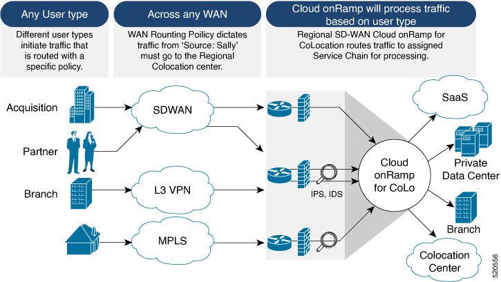
Deploy Cloud onRamp for Colocation Solution
This topic outlines the sequence of how to get started with the colo devices and build clusters on Cisco vManage. Once a cluster is created and configured, you can follow the steps that are required to activate the cluster. Understand how to design service groups or service chains and attach them to an activated cluster. The supported Day-N operations are also listed in this topic.
-
Complete the solution prerequisites and requirements. See Prerequisites and Requirements of Cloud onRamp for Colocation Solution .
-
Complete wiring the CSP devices (set up CIMC for initial CSP access) and Cisco Catalyst 9500-40X or Cisco Catalyst 9500-48Y4C switches (set up console server) along with OOB or management switches. Power on all devices.
-
Set up and configure DHCP server. See Provision DHCP Server per Colocation.
-
-
Verify the installed version of Cisco NFVIS and install NFVIS, if necessary. See Install Cisco NFVIS Cloud OnRamp for Colocation on Cisco CSP.
-
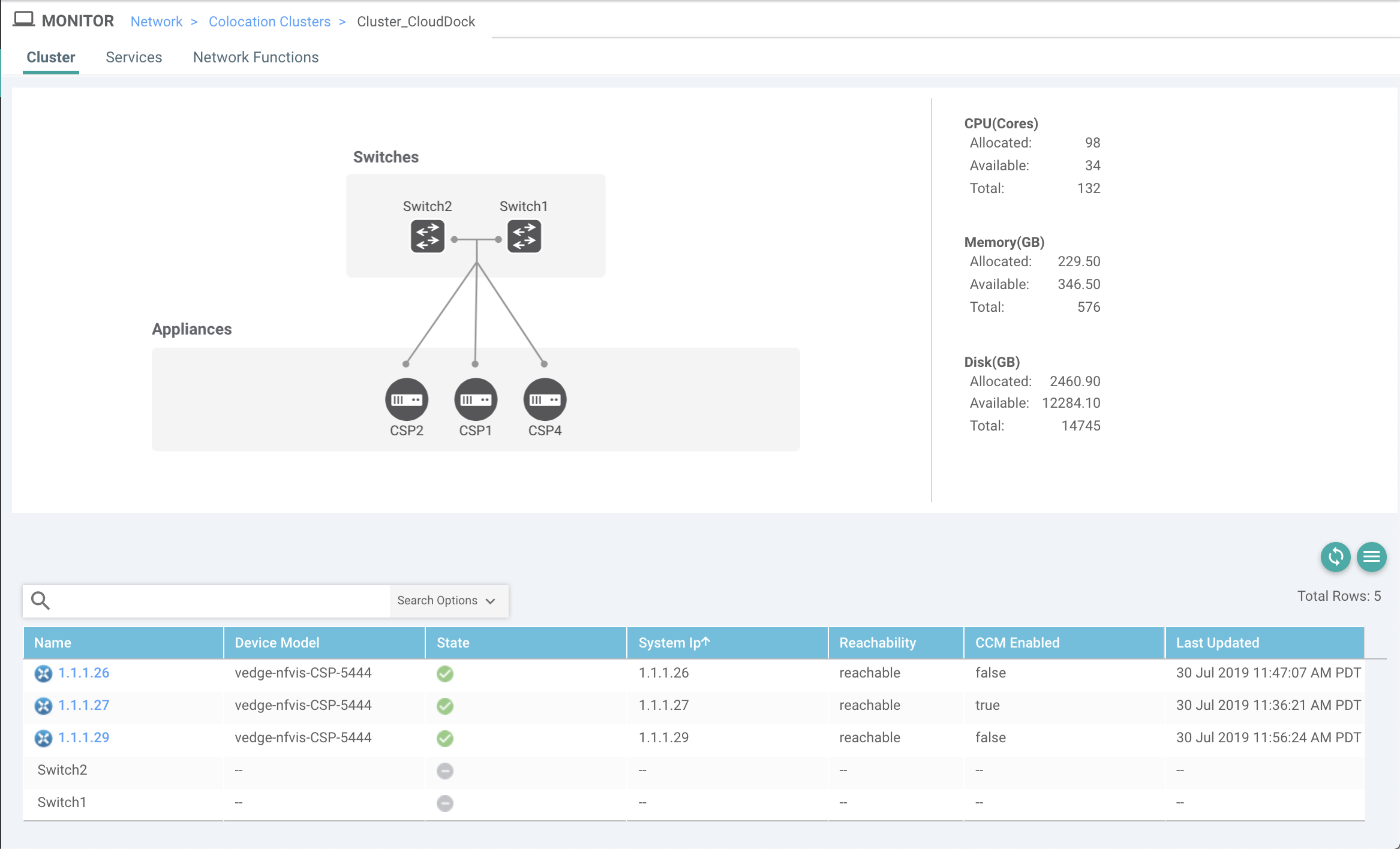
Set up or provision a cluster. A cluster constitutes of all the physical devices including CSP devices, and Cisco Catalyst 9500-40X or Cisco Catalyst 9500-48Y4C switches. See Get Started with Cisco SD-WAN Cloud onRamp for CoLocation Solution.
-
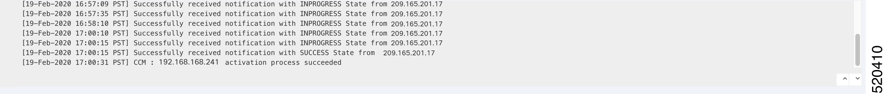
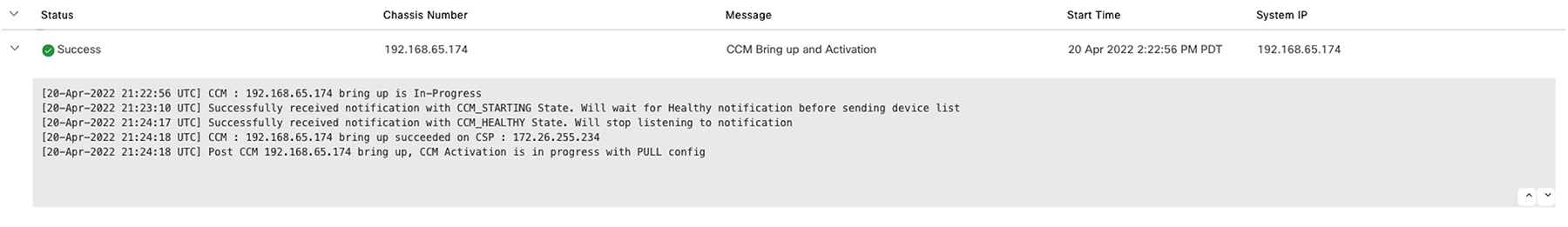
Bring up CSP devices. See Bring Up Cloud Services Platform Devices.
-
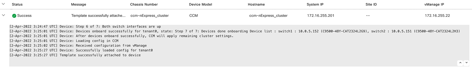
Bring up Cisco Catalyst 9500-40X or Cisco Catalyst 9500-48Y4C switches. See Bring Up Switch Devices.
-
Provision and configure a cluster. See Provision and Configure Cluster.
Configure a cluster through cluster settings. See Cluster Settings.
-
-
Activate a cluster. See Create and Activate Clusters.
-
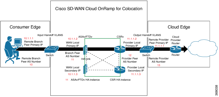
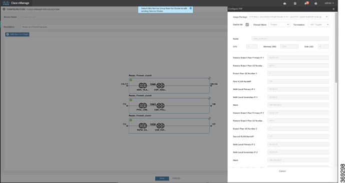
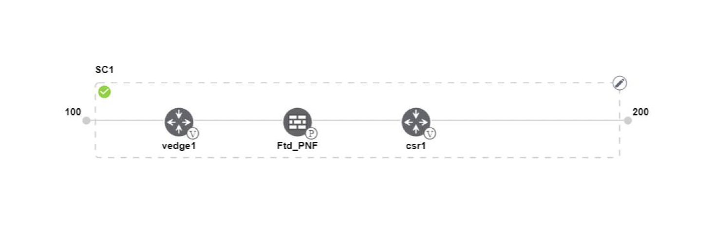
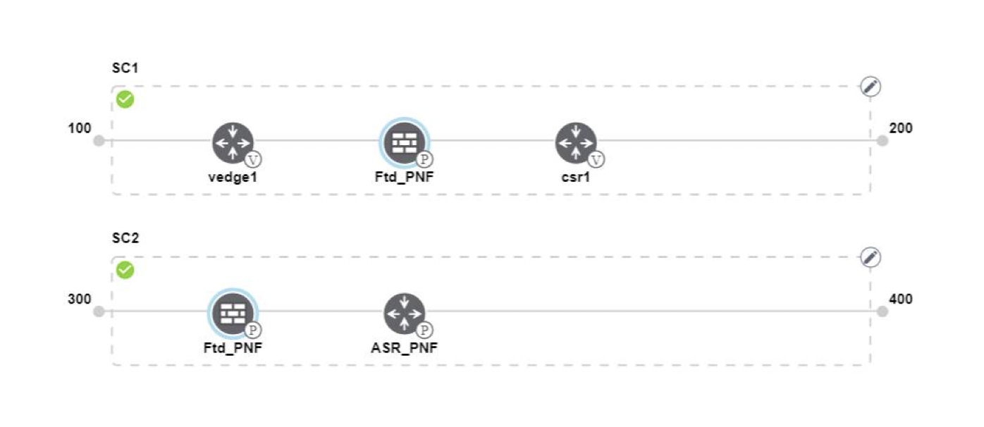
Design service group or service chain. See Manage Service Groups.

Note
You can design a service chain and create a service group anytime before creating clusters or activating clusters after all VMs are uploaded to the repository.
-
Attach or Detach service group and service chains to a cluster. See Attach or Detach a Service Group in a Cluster.
Note
Service chains can be attached to a cluster after the cluster is active.
-
(Optional) Perform all Day-N operations.
-
Detach a service group to detach service chains. See Attach or Detach a Service Group in a Cluster.
-
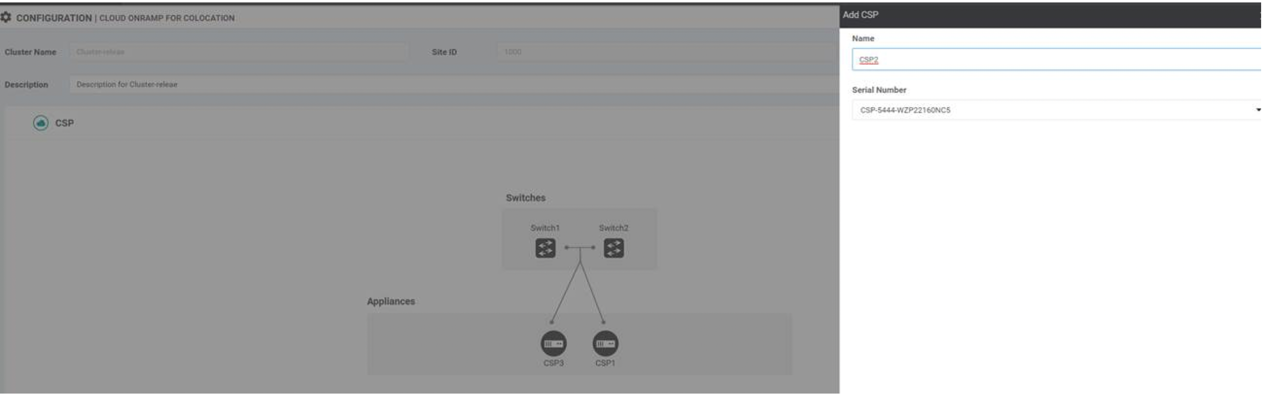
Add and delete CSP devices from a cluster. See Add Cloud OnRamp Colocation Devices and Delete Cloud OnRamp for Colocation Devices.
-
Deactivate a cluster. See Remove Cluster.
-
Reactivate a cluster. See Reactivate Cluster.
-
Design more service group or service chain. See Create Service Chain in a Service Group.
-


 Feedback