Configure Network Interfaces

In the Cisco SD-WAN overlay network design, interfaces are associated with VPNs. The interfaces that participate in a VPN are configured and enabled in that VPN. Each interface can be present only in a single VPN.

At a high level, for an interface to be operational, you must configure an IP address for the interface and mark it as operational (no shutdown). In practice, you always configure additional parameters for each interface.

You can configure up to 512 interfaces on a Cisco IOS XE SD-WAN device. This number includes physical interfaces, loopback interfaces, and subinterfaces.


Note

To maximize the efficiency of the load-balancing among Cisco vSmart Controllers, use sequential numbers when assigning system IP addresses to the Cisco IOS XE SD-WAN devices in the domain. Example of a sequential numbering schemes is 172.1.1.1, 172.1.1.2, 172.1.1.3, and so on.


Note

Ensure that any network interface configured on a device has a unique IP address.


Configure VPN

VPN

Use the VPN template for all Cisco SD-WAN devices running the Cisco SD-WAN software.

To configure VPNs using Cisco vManage templates, follow this general workflow:

  1. Create VPN feature templates to configure VPN parameters. You create a separate VPN feature template for each VPN. For example, create one feature template for VPN 0, a second for VPN 1, and a third for VPN 512.

    For Cisco vManage Network Management Systems and Cisco vSmart Controllers, you can configure only VPNs 0 and 512. Create templates for these VPNs only if you want to modify the default settings for the VPN. For Cisco IOS XE SD-WAN devices, you can create templates for these two VPNs and for additional VPN feature templates to segment service-side user networks.

    • VPN 0Transport VPN, which carries control traffic via the configured WAN transport interfaces. Initially, VPN 0 contains all of a device's interfaces except for the management interface, and all interfaces are disabled.

    • VPN 512Management VPN, which carries out-of-band network management traffic among the Cisco IOS XE SD-WAN devices in the overlay network. The interface used for management traffic resides in VPN 512. By default, VPN 512 is configured and enabled on all Cisco IOS XE SD-WAN devices. For controller devices, by default, VPN 512 is not configured.

    • VPNs 1511, 51365530Service VPNs, for service-side data traffic on Cisco IOS XE SD-WAN devices.

  2. Create interface feature templates to configure the interfaces in the VPN. See VPN-Interface-Ethernet.

Create a VPN Template


Note

Cisco IOS XE SD-WAN devices use VRFs for segmentation and network isolation. However, the following steps still apply if you are configuring segmentation for Cisco IOS XE SD-WAN devices through Cisco vManage. When you complete the configuration, the system automatically converts the VPNs to VRFs for Cisco IOS XE SD-WAN devices.


Procedure


Step 1

In Cisco vManage NMS, choose Configuration > Templates.

Step 2

In the Device tab, click Create Template.

Step 3

From the Create Template drop-down, select From Feature Template.

Step 4

From the Device Model drop-down, select the type of device for which you are creating the template.

Step 5

To create a template for VPN 0 or VPN 512:

  1. Click the Transport & Management VPN tab located directly beneath the Description field, or scroll to the Transport & Management VPN section.

  2. From the VPN 0 or VPN 512 drop-down, click Create Template. The VPN template form displays. The top of the form contains fields for naming the template, and the bottom contains fields for defining VPN parameters.

Step 6

To create a template for VPNs 1 through 511, and 513 through 65527:

  1. Click the Service VPN tab located directly beneath the Description field, or scroll to the Service VPN section.

  2. Click the Service VPN drop-down.

  3. From the VPN drop-down, click Create Template. The VPN template form displays. The top of the form contains fields for naming the template, and the bottom contains fields for defining VPN parameters.

Step 7

In the Template Name field, enter a name for the template. The name can be up to 128 characters and can contain only alphanumeric characters.

Step 8

In the Template Description field, enter a description of the template. The description can be up to 2048 characters and can contain only alphanumeric characters.


Changing the Scope for a Parameter Value

When you first open a feature template, for each parameter that has a default value, the scope is set to Default (a ), and the default setting or value is shown. To change the default or to enter a value, click the scope drop-down to the left of the parameter field and select one of the following:

Parameter Name

Description

Device Specific

Use a device-specific value for the parameter. For device-specific parameters, you cannot enter a value in the feature template. You enter the value when you attach a device to a device template.

When you click Device Specific, the Enter Key box opens. This box displays a key, which is a unique string that identifies the parameter in a CSV file that you create. This file is an Excel spreadsheet that contains one column for each key. The header row contains the key names (one key per column), and each row after that corresponds to a device and defines the values of the keys for that device. You upload the CSV file when you attach a device to a device template. For more information, see Create a Template Variables Spreadsheet

To change the default key, type a new string and move the cursor out of the Enter Key box.

Examples of device-specific parameters are system IP address, hostname, GPS location, and site ID.

Global

Enter a value for the parameter, and apply that value to all devices.

Examples of parameters that you might apply globally to a group of devices are DNS server, syslog server, and interface MTUs.

Once you have created and named the template, enter the following values. Parameters marked with an asterisk are required.

Configure Basic VPN Parameters

To configure basic VPN parameters, choose the Basic Configuration tab and then configure the following parameters. Parameters marked with an asterisk are required to configure a VPN.

Parameter Name Description
VPN*

Enter the numeric identifier of the VPN.

Range for Cisco IOS XE SD-WAN devices: 0 through 65527

Values for Cisco vSmart Controller and Cisco vManage devices: 0, 512

Name Enter a name for the VPN.
Note 

For Cisco IOS XE SD-WAN devices, you cannot enter a device-specific name for the VPN.


Note

To complete the configuration of the transport VPN on a router, you must configure at least one interface in VPN 0.


To save the feature template, click Save.

Configure DNS and Static Hostname Mapping

To configure DNS addresses and static hostname mapping, click the DNS tab and configure the following parameters:

Parameter Name Options Description
Primary DNS Address Select either IPv4 or IPv6, and enter the IP address of the primary DNS server in this VPN.
New DNS Address Click New DNS Address and enter the IP address of a secondary DNS server in this VPN. This field appears only if you have specified a primary DNS address.
Mark as Optional Row Check Mark as Optional Row to mark this configuration as device-specific. To include this configuration for a device, enter the requested variable values when you attach a device template to a device, or create a template variables spreadsheet to apply the variables.
Hostname Enter the hostname of the DNS server. The name can be up to 128 characters.
List of IP Addresses Enter up to eight IP addresses to associate with the hostname. Separate the entries with commas.
To save the DNS server configuration, click Add.

To save the feature template, click Save.

Mapping Host Names to IP Addresses


! IP DNS-based host name-to-address translation is enabled
  ip domain lookup
! Specifies hosts 192.168.1.111 and 192.168.1.2 as name servers
  ip name-server 192.168.1.111 192.168.1.2
! Defines cisco.com as the default domain name the device uses to complete
! Set the name for unqualified host names  
  ip domain name cisco.com

Configure Interfaces in the WAN Transport VPN (VPN 0)

This topic describes how to configure the general properties of WAN transport and service-side network interfaces. For information about how to configure specific interface types and properties—including cellular interfaces, DHCP, PPPoE, VRRP, and WLAN interfaces.

VPN 0 is the WAN transport VPN. This VPN handles all control plane traffic, which is carried over OMP sessions, in the overlay network. For a Cisco IOS XE SD-WAN device device to participate in the overlay network, at least one interface must be configured in VPN 0, and at least one interface must connect to a WAN transport network, such as the Internet or an MPLS or a metro Ethernet network. This WAN transport interface is referred to as a tunnel interface. At a minimum, for this interface, you must configure an IP address, enable the interface, and set it to be a tunnel interface.

To configure a tunnel interface on a Cisco vSmart Controller or a Cisco vManage NMS, you create an interface in VPN 0, assign an IP address or configure the interface to receive an IP address from DHCP, and mark it as a tunnel interface. The IP address can be either an IPv4 or IPv6 address. To enable dual stack, configure both address types. You can optionally associate a color with the tunnel.


Note

You can configure IPv6 addresses only on transport interfaces, that is, only in VPN 0.


Tunnel interfaces on Cisco IOS XE SD-WAN devices must have an IP address, a color, and an encapsulation type. The IP address can be either an IPv4 or IPv6 address. To enable dual stack, configure both address types.

On Cisco vSmart Controllers and Cisco vSmart Controller NMSs, interface-name can be either eth number or loopback number. Because Cisco vSmart Controllers and Cisco vSmart Controller NMSs participate only in the overlay network's control plane, the VPNs that you can configure on these devices are VPN 0 and VPN 512. Hence, all interfaces are present only on these VPNs.

To enable the interface, include the no shutdown command.

For the tunnel interface, you can configure a static IPv4 or IPv6 address, or you can configure the interface to receive its address from a DHCP server. To enable dual stack, configure both an IPv4 and an IPv6 address on the tunnel interface.

Color is a Cisco SD-WAN software construct that identifies the transport tunnel. It can be 3g, biz-internet, blue, bronze, custom1, custom2, custom3, default, gold, green, lte, metro-ethernet, mpls, private1 through private6, public-internet, red, and silver. The colors metro-ethernet, mpls, and private1 through private6 are referred to as private colors, because they use private addresses to connect to the remote side Cisco IOS XE SD-WAN device in a private network. You can use these colors in a public network provided that there is no NAT device between the local and remote Cisco IOS XE SD-WAN devices.

To limit the remote TLOCs that the local TLOC can establish BFD sessions with, mark the TLOC with the restrict option. When a TLOC is marked as restricted, a TLOC on the local router establishes tunnel connections with a remote TLOC only if the remote TLOC has the same color.

On a Cisco vSmart Controller or Cisco vSmart Controller NMS, you can configure one tunnel interface. On a Cisco IOS XE SD-WAN device, you can configure up to eight tunnel interfaces.

On Cisco IOS XE SD-WAN devices, you must configure the tunnel encapsulation. The encapsulation can be either IPsec or GRE. For IPsec encapsulation, the default MTU is 1442 bytes, and for GRE it is 1468 bytes, These values are a function of overhead required for BFD path MTU discovery, which is enabled by default on all TLOCs. (For more information, see Configuring Control Plane and Data Plane High Availability Parameters .) You can configure both IPsec and GRE encapsulation by including two encapsulation commands under the same tunnel-interface command. On the remote Cisco IOS XE SD-WAN device, you must configure the same tunnel encapsulation type or types so that the two routers can exchange data traffic. Data transmitted out an IPsec tunnel can be received only by an IPsec tunnel, and data sent on a GRE tunnel can be received only by a GRE tunnel. The Cisco SD-WAN software automatically selects the correct tunnel on the destination Cisco IOS XE SD-WAN device.

A tunnel interface allows only DTLS, TLS, and, for Cisco IOS XE SD-WAN devices, IPsec traffic to pass through the tunnel. To allow additional traffic to pass without having to create explicit policies or access lists, enable them by including one allow-service command for each service. You can also explicitly disallow services by including the no allow-service command. Note that services affect only physical interfaces. You can allow or disallow these services on a tunnel interface:

Service

Cisco vSmart Controller

Cisco vSmart Controller

all (Overrides any commands that allow or disallow individual services)

X

X

bgp

dhcp (for DHCPv4 and DHCPv6)

dns

https

X

icmp

X

X

netconf

X

ntp

ospf

sshd

X

X

stun

X

X

The allow-service stun command pertains to allowing or disallowing a Cisco IOS XE SD-WAN device to generate requests to a generic STUN server so that the device can determine whether it is behind a NAT and, if so, what kind of NAT it is and what the device's public IP address and public port number are. On a Cisco IOS XE SD-WAN device that is behind a NAT, you can also have tunnel interface to discover its public IP address and port number from the Cisco vBond Orchestrator.

With this configuration, the Cisco IOS XE SD-WAN device uses the Cisco vBond Orchestrator as a STUN server, so the router can determine its public IP address and public port number. (With this configuration, the router cannot learn the type of NAT that it is behind.) No overlay network control traffic is sent and no keys are exchanged over tunnel interface configured to the the Cisco vBond Orchestrator as a STUN server. However, BFD does come up on the tunnel, and data traffic can be sent on it. Because no control traffic is sent over a tunnel interface that is configured to use the Cisco vBond Orchestrator as a STUN server, you must configure at least one other tunnel interface on the Cisco IOS XE SD-WAN device so that it can exchange control traffic with the Cisco vSmart Controller and the Cisco vSmart Controller NMS.

You can log the headers of all packets that are dropped because they do not match a service configured with an allow-service command. You can use these logs for security purposes, for example, to monitor the flows that are being directed to a WAN interface and to determine, in the case of a DDoS attack, which IP addresses to block.

Configure the System Interface

For each Cisco IOS XE SD-WAN device, you configure a system interface with the system system-ip command. The system interface's IP address is a persistent address that identifies the Cisco IOS XE SD-WAN device. It is similar to a router ID on a regular router, which is the address used to identify the router from which packets originated.

Specify the system IP address as an IPv4 address in decimal four-part dotted notation. Specify just the address; the prefix length (/32) is implicit.

The system IP address can be any IPv4 address except for 0.0.0.0/8, 127.0.0.0/8, and 224.0.0.0/4, and 240.0.0.0/4 and later. Each device in the overlay network must have a unique system IP address. You cannot use this same address for another interface in VPN 0.

The system interface is placed in VPN 0, as a loopback interface named system. Note that this is not the same as a loopback address that you configure for an interface.

To display information about the system interface, use the show interface command. For example:

The system IP address is used as one of the attributes of the OMP TLOC. Each TLOC is uniquely identified by a 3-tuple comprising the system IP address, a color, and an encapsulation. To display TLOC information, use the show omp tlocs command.

For device management purposes, it is recommended as a best practice that you also configure the same system IP address on a loopback interface that is located in a service-side VPN that is an appropriate VPN for management purposes. You use a loopback interface because it is always reachable when the router is operational and when the overlay network is up. If you were to configure the system IP address on a physical interface, both the router and the interface would have to be up for the router to be reachable. You use a service-side VPN because it is reachable from the data center. Service-side VPNs are VPNs other than VPN 0 (the WAN transport VPN) and VPN 512 (the management VPN), and they are used to route data traffic.


Note

Use of port-channels on the Service Side VPN is not supported on Cisco IOS XE SD-WAN devices.

Configure Control Plane High Availability

A highly available Cisco SD-WAN network contains two or more Cisco vSmart Controllers in each domain. A Cisco SD-WAN domain can have up to eight Cisco vSmart Controllers, and each Cisco IOS XE SD-WAN device, by default, connects to two of them. You change this value on a per-tunnel basis:

Configure Other Interfaces

Configure Interfaces in the Management (VRF mgmt-intf)

On all Cisco SD-WAN devices, VPN 512 is used for out-of-band management, by default as part of the factory-default configuration. On Cisco IOS XE SD-WAN devices the management VPN is converted to VRF Mgmt-Intf.

Cisco XE SD-WAN devices use VRFs in place of VPNs.

Device# show sdwan running-config | sec vrf definition Mgmt-intf
vrf definition Mgmt-intf
 address-family ipv4
  exit-address-family
 !
 address-family ipv6
  exit-address-family
 !
============
interface GigabitEthernet0
 no shutdown
 vrf forwarding Mgmt-intf
 negotiation auto
exit
============
config-t
ip route vrf Mgmt-intf 10.0.0.1 10.0.0.1 

To display information about the configured management interfaces, use the show interface command. For example:

Device# show interface gigabitEthernet0 
GigabitEthernet0 is up, line protocol is up 
  Hardware is RP management port, address is d478.9bfe.9f7f (bia d478.9bfe.9f7f)
  Internet address is 10.34.9.177/16
  MTU 1500 bytes, BW 1000000 Kbit/sec, DLY 10 usec, 
     reliability 255/255, txload 1/255, rxload 1/255
  Encapsulation ARPA, loopback not set
  Keepalive set (10 sec)
  Full Duplex, 1000Mbps, link type is auto, media type is RJ45
  output flow-control is unsupported, input flow-control is unsupported
  ARP type: ARPA, ARP Timeout 04:00:00
  Last input 00:00:00, output 00:00:00, output hang never
  Last clearing of "show interface" counters never
  Input queue: 0/75/0/0 (size/max/drops/flushes); Total output drops: 0
  Queueing strategy: fifo
  Output queue: 0/40 (size/max)
  5 minute input rate 8000 bits/sec, 12 packets/sec
  5 minute output rate 1000 bits/sec, 2 packets/sec
     4839793 packets input, 415574814 bytes, 0 no buffer
     Received 3060073 broadcasts (0 IP multicasts)
     0 runts, 0 giants, 0 throttles 
     0 input errors, 0 CRC, 0 frame, 0 overrun, 0 ignored
     0 watchdog, 0 multicast, 0 pause input
     82246 packets output, 41970224 bytes, 0 underruns
     Output 0 broadcasts (0 IP multicasts)
     0 output errors, 0 collisions, 0 interface resets
     0 unknown protocol drops
     0 babbles, 0 late collision, 0 deferred
     0 lost carrier, 0 no carrier, 0 pause output
     0 output buffer failures, 0 output buffers swapped out


Note

VPN 512 is not advertised in the overlay. It is local to the device. If you need a management VPN that is reachable through the overlay, create a VPN with a number other than 512.


Configure Loopback Interfaces

Use the interface name format loopback string, where string can be any alphanumeric value and can include underscores (_) and hyphens (–). The total interface name, including the string "loopback", can be a maximum of 16 characters long. (Note that because of the flexibility of interface naming in the CLI, the interfaces lo0 and loopback0 are parsed as different strings and as such are not interchangeable. For the CLI to recognize as interface as a loopback interface, its name must start with the full string loopback.)

One special use of loopback interfaces is to configure data traffic exchange across private WANs, such as MPLS or metro Ethernet networks. To allow a router that is behind a private network to communicate directly over the private WAN with other edge routers, you direct data traffic to a loopback interface that is configured as a tunnel interface rather than to an actual physical WAN interface.

Configure Subinterfaces

When you create a subinterface that does not specify an IP MTU value, the subinterface inherits the IP MTU value from the parent interface. If you want the subinterface to have a different IP MTU value, use the ip mtu command in the subinterface configuration to set the IP MTU for the sub interface.

For example:

interface GigabitEthernet0/0/0
description Main interface
no shutdown
arp timeout 1200
no ip address
ip mtu 1504 
mtu 1504 
 
interface GigabitEthernet0/0/0.100
description LAN VPN 1
no shutdown
encapsulation dot1Q 100
ip address 10.0.0.1 255.255.255.0
ip mtu 1500
mtu 1500

Role-Based Access Control by VPN

VPN Dashboard Overview

Users configured with VPN group can access only the VPN Dashboard, and it is read-only access. User with Admin access can create the VPN groups and has access to both Admin Dashboard and VPN Dashboard(s). Admin user can view these dashboards in the left panel as shown in the following figures:

Configure and Manage VPN Segments

To configure VPN Segments:

  1. Navigate to Administration > VPN Segments in Cisco vManage. The following web page displays with the list of segments that are configured.

  2. To edit or delete an existing segment, click the Edit or Delete in the More Info (…) column on the right side.

  3. To add new segment, click Add Segment. Add Segment window appears.

  4. Enter the name of the segment in the Segment Name field.

  5. Enter the number of VPNs you want to configure in VPN Number field.

  6. Click Add to add a new segment.

Configure and Manage VPN Groups

To configure VPN Groups:

  1. Navigate to Administration > VPN Groups in Cisco vManage. The following web page displays with the list of segments that are configured.

  2. To edit or delete an VPN group, click the Edit or Delete in the More Info (…) column on the right side.

  3. To view the existing VPN in the dashboard, click on View Dashboard in the More Info column. The VPN Dashboard displays the device details of the VPN device configured.

  4. To add new VPN group, click Add Group. Add VPN Group window appears.

  5. In the Create VPN Group pane, Enter VPN group name in the VPN Group Name field.

  6. Enter a brief description of the VPN in the Description field.

  7. Enable the user group access checkbox and enter the User Group Name.

  8. In the Assign Segment pane, click on Add Segment drop-down to add new or existing segment to the VPN group.

  9. Enter the Segment Name and VPN Number in the respective fields.

  10. Click Add to add the configure VPN group to a device.

Configure User with User group

To create users with user group that is associated with the VPN group:

  1. Navigate to Administration > Manage Users from Cisco vManage. The manage Users window appears.

  2. To edit, delete, or change password for an existing user, click the Edit, Delete, or Change Password in the More Info (…) column on the right side.

  3. Click on Add User to add a new user.

  4. In the Add New User page, add Full Name, Username, Password, and Confirm Password details.

  5. In the User Group drop-down, select the user group where you want to add a user.

  6. If you want to add a User Group, click on Add User Group button.

  7. Enter the user group name in the Group Name field.

  8. Select the Read or Write checkbox that you want to assign to a user group as shown in the figure.

Configure Interface Properties

Set the Interface Speed

When a Cisco IOS XE SD-WAN device comes up, the Cisco SD-WAN software autodetects the SFPs present in the router and sets the interface speed accordingly. The software then negotiates the interface speed with the device at the remote end of the connection to establish the actual speed of the interface. To display the hardware present in the router, use the show hardware inventory command:

To display the actual speed of each interface, use the show interface command. Here, interface ge0/0, which connects to the WAN cloud, is running at 1000 Mbps (1Gbps; it is the 1GE PIM highlighted in the output above), and interface ge0/1, which connects to a device at the local site, has negotiated a speed of 100 Mbps.

For non-physical interfaces, such as those for the system IP address and loopback interfaces, the interface speed is set by default to 10 Mbps.

To override the speed negotiated by the two devices on the interface, disable autonegotiation and configure the desired speed:

For Cisco vSmart Controllers and Cisco vManage NMS systems, the initial interface speeds are 1000 Mbps, and the operating speed is negotiated with the device at the remote end of the interface. The controller interface speed may vary depending upon the virtualization platform, the NIC used, and the drivers that are present in the software.

Set the Interface MTU

By default, all interfaces have an MTU of 1500 bytes. You can modify this on an interface:

The MTU can range from 576 through 2000 bytes.

To display an interface's MTU, use the show interface command.

For Cisco vBond Orchestrator, Cisco vManage, and Cisco vSmart Controller devices, you can configure interfaces to use ICMP to perform path MTU (PMTU) discovery. When PMTU discovery is enabled, the device to automatically negotiates the largest MTU size that the interface supports in an attempt to minimize or eliminate packet fragmentation:

On Cisco IOS XE SD-WAN device, the Cisco SD-WAN BFD software automatically performs PMTU discovery on each transport connection (that is, for each TLOC, or color). BFD PMTU discovery is enabled by default, and it is recommended that you use it and not disable it. To explicitly configure BFD to perform PMTU discovery, use the bfd color pmtu-discovery configuration command. However, you can choose to instead use ICMP to perform PMTU discovery:

BFD is a data plane protocol and so does not run on Cisco vBond Orchestrator, Cisco vManage, and Cisco vSmart Controller devices.

Monitoring Bandwidth on a Transport Circuit

You can monitor the bandwidth usage on a transport circuit, to determine how the bandwidth usage is trending. If the bandwidth usage starts approaching a maximum value, you can configure the software to send a notification. Notifications are sent as Netconf notifications, which are sent to the Cisco vManage NMS, SNMP traps, and syslog messages. You might want to enable this feature for bandwidth monitoring, such as when you are doing capacity planning for a circuit or when you are gathering trending information about bandwidth utilization. You might also enable this feature to receive alerts regarding bandwidth usage, such as if you need to determine when a transport interface is becoming so saturated with traffic that a customer's traffic is impacted, or when customers have a pay-per-use plan, as might be the case with LTE transport.

To monitor interface bandwidth, you configure the maximum bandwidth for traffic received and transmitted on a transport circuit. The maximum bandwidth is typically the bandwidth that has been negotiated with the circuit provider. When bandwidth usage exceeds 85 percent of the configured value for either received or transmitted traffic, a notification, in the form of an SNMP trap, is generated. Specifically, interface traffic is sampled every 10 seconds. If the received or transmitted bandwidth exceeds 85 percent of the configured value in 85 percent of the sampled intervals in a continuous 5-minute period, an SNMP trap is generated. After the first trap is generated, sampling continues at the same frequency, but notifications are rate-limited to once per hour. A second trap is sent (and subsequent traps are sent) if the bandwidth exceeds 85 percent of the value in 85 percent of the 10-second sampling intervals over the next 1-hour period. If, after 1 hour, another trap is not sent, the notification interval reverts to 5 minutes.

You can monitor transport circuit bandwidth on Cisco IOS XE SD-WAN devices and on Cisco vManage NMSs.

To generate notifications when the bandwidth of traffic received on a physical interface exceeds 85 percent of a specific bandwidth, configure the downstream bandwidth:

To generate notifications when the bandwidth of traffic transmitted on a physical interface exceeds 85 percent of a specific bandwidth, configure the upstream bandwidth:

In both configuration commands, the bandwidth can be from 1 through 2147483647 (232 / 2) – 1 kbps.

To display the configured bandwidths, look at the bandwidth-downstream and bandwidth-upstream fields in the output of the show interface detail command. The rx-kbps and tx-kbps fields in this command shows the current bandwidth usage on the interface.

Enable DHCP Server using Cisco vManage

Table 1. Feature History

Feature Name

Release Information

Feature Description

DHCP Option Support

Cisco IOS XE SD-WAN Release 16.12.1b

This feature allows DHCP server options, 43 and 191 to configure vendor-specific information in client-server exchanges.

Use the DHCP-Server template for all Cisco SD-WANs

You enable DHCP server functionality on a Cisco SD-WAN device interface so it can assign IP addresses to hosts in the service-side network.

To configure a Cisco SD-WAN device to act as a DHCP server using Cisco vManage templates:

  1. Create a DHCP-Server feature template to configure DHCP server parameters, as described in this topic.

  2. Create one or more interface feature templates, as described in the VPN-Interface-Ethernet and the VPN-Interface-PPP-Ethernet help topics.

  3. Create a VPN feature template to configure VPN parameters. See the VPN help topic.

To configure a Cisco IOS XE SD-WAN device interface to be a DHCP helper so that it forwards broadcast DHCP requests that it receives from DHCP servers, in the DHCP Helper field of the applicable interfaces template, enter the addresses of the DHCP servers.​

Navigate to the Template Screen and Name the Template

  1. In Cisco vManage NMS, select the Configuration ► Templates screen.

  2. In the Device tab, click Create Template.

  3. From the Create Template drop-down, select From Feature Template.

  4. From the Device Model drop-down, select the type of device for which you are creating the template.

  5. Click the Service VPN tab located directly beneath the Description field, or scroll to the Service VPN section.

  6. Click the Service VPN drop-down.

  7. Under Additional VPN Templates, located to the right of the screen, click VPN Interface.

  8. From the Sub-Templates drop-down, select DHCP Server.

  9. From the DHCP Server drop-down, click Create Template. The DHCP-Server template form is displayed. The top of the form contains fields for naming the template, and the bottom contains fields for defining DHCP Server parameters.
  10. In the Template Name field, enter a name for the template. The name can be up to 128 characters and can contain only alphanumeric characters.

  11. In the Template Description field, enter a description of the template. The description can be up to 2048 characters and can contain only alphanumeric characters.

When you first open a feature template, for each parameter that has a default value, the scope is set to Default (indicated by a check mark), and the default setting or value is shown. To change the default or to enter a value, click the scope drop-down to the left of the parameter field.

Minimum DHCP Server Configuration

To configure DHCP server functionality, select the Basic Configuration tab and configure the following parameters. Parameters marked with an asterisk as required to configure DHCP servers.

Table 2.

Parameter Name

Description

Address Pool*

Enter the IPv4 prefix range, in the format prefix/length, for the pool of addresses in the service-side network for which the router interface acts as DHCP server.

Exclude Addresses

Enter one or more IP addresses to exclude from the DHCP address pool. To specify multiple individual addresses, list them separated by a comma. To specify a range of addresses, separate them with a hyphen.

Maximum Leases

Specify the number of IP addresses that can be assigned on this interface.Range: 0 through 4294967295

Lease Time

Specify how long a DHCP-assigned IP address is valid.Range: 0 through 4294967295 seconds

Offer Time

Specify how long the IP address offered to a DHCP client is reserved for that client. By default, an offered IP address is reserved indefinitely, until the DHCP server runs out of addresses. At that point, the address is offered to another client.Range: 0 through 4294967295 secondsDefault: 600 seconds

Administrative State

Select Up to enable or Down to disable the DHCP functionality on the interface. By default, DHCP server functionality is disabled on an interface.

To save the feature template, click Save.

Configure Static Leases

To configure a static lease to assign a static IP address to a client device on the service-side network, click the Static Lease tab. Then click Add New Static Lease and configure the following parameters:

Table 3.

Parameter Name

Description

MAC Address

Enter the MAC address of the client to which the static IP address is being assigned.

IP Address

Enter the static IP address to assign to the client.

Hostname

Enter the hostname of the client device.

To edit a static lease, click the pencil icon to the right of the entry.

To remove a static lease, click the trash icon to the right of the entry.

To save the feature template, click Save.

Configure Advanced Options

To configure a advanced DHCP server options, click the Advanced tab and then configure the following parameters:

Table 4.

Parameter Name

Description

Interface MTU

Specify the maximum MTU size of packets on the interface.Range: 68 to 65535 bytes

Domain Name

Specify the domain name that the DHCP client uses to resolve hostnames.

Default Gateway

Enter the IP address of a default gateway in the service-side network.

DNS Servers

Enter one or more IP address for a DNS server in the service-side network. Separate multiple entries with a comma. You can specify up to eight addresses.

TFTP Servers

Enter the IP address of a TFTP server in the service-side network. You can specify one or two addresses. If two, separate them with a comma.

To save the feature template, click Save.

Configure DHCP server using CLI

Device# config-transaction
Device(dhcp-config)# ip dhcp pool DHCP-POOL
Device(dhcp-config)# network 10.1.1.1 255.255.255.0
Device(dhcp-config)# default-router 10.1.1.2
Device(dhcp-config)# dns-server 172.16.0.1
Device(dhcp-config)# domain-name DHCP-DOMAIN
Device(dhcp-config)# exit
Device(config)ip dhcp excluded-address 10.1.1.2 10.1.1.10
Device(

Release Information

Introduced in Cisco vManage NMS in Release 15.2.

Configuring PPPoE

The Point-to-Point Protocol over Ethernet (PPPoE) connects multiple users over an Ethernet local area network to a remote site through common customer premises equipment. PPPoE is commonly used in a broadband aggregation, such as by digital subscriber line (DSL). PPPoE provides authentication with the CHAP or PAP protocol. In the Cisco SD-WAN overlay network, Cisco SD-WAN devices can run the PPPoE client. The PPPoE server component is not supported.

To configure PPPoE client on a Cisco SD-WAN device, you create a PPP logical interface and link it to a physical interface. The PPPoE connection comes up when the physical interface comes up. You can link a PPP interface to only one physical interface on a Cisco SD-WAN device, and you can link a physical interface to only one PPP interface. To enable more than one PPPoE interfaces on a Cisco SD-WAN device, configure multiple PPP interfaces.

It is recommended that you configure quality of service (QoS) and shaping rate on a PPPoE-enabled physical interface, and not on the PPP interface.

PPPoE-enabled physical interfaces do not support:

  • 802.1Q

  • Subinterfaces

  • NAT, PMTU, and tunnel interfaces. These are configured on the PPP interface and therefore not available on PPPoE-enabled interfaces.

The Cisco SD-WAN implementation of PPPoE does not support the Compression Control Protocol (CCP) options, as defined in RFC 1962.

Configure PPPoE from vManage Templates

To use vManage templates to configure PPPoE on Cisco IOS XE SD-WAN device, you create three feature templates and one device template:

  • Create a VPN-Interface-PPP feature template to configure PPP parameters for the PPP virtual interface.

  • Create a VPN-Interface-PPP-Ethernet feature template to configure a PPPoE-enabled interface.

  • Optionally, create a VPN feature template to modify the default configuration of VPN 0.

  • Create a device template that incorporates the VPN-Interface-PPP, VPN-Interface-PPP-Ethernet, and VPN feature templates.

To create a VPN-Interface-PPP feature template to configure PPP parameters for the PPP virtual interface:

Table 5.

Parameter Field

Procedure

Template Name

Enter a name for the template. It can be up to 128 alphanumeric characters.

Description

Enter a description for the template. It can be up to 2048 alphanumeric characters.

Shutdown

Click No to enable the PPP virtual interface.

Interface Name

Enter the number of the PPP interface. It can be from 1 through 31.

Description (optional)

Enter a description for the PPP virtual interface.

Authentication Protocol

Select either CHAP or PAP to configure one authentication protocol, or select PAP and CHAP to configure both. For CHAP, enter the hostname and password provided by your ISP. For PAP, enter the username and password provided by your ISP. If you are configuring both PAP and CHAP, to use the same username and password for both, click Same Credentials for PAP and CHAP.

AC Name (optional)

Select the PPP tab, and in the AC Name field, enter the name of the the name of the access concentrator used by PPPoE to route connections to the Internet.

IP MTU

Click the Advanced tab, and In the IP MTU field, ensure that the IP MTU is at least 8 bytes less than the MTU on the physical interface. The maximum MTU for a PPP interface is 1492 bytes. If the PPPoE server does not specify a maximum receive unit (MRU), the MTU value for the PPP interface is used as the MRU.

Save

Click Save to save the feature template.

  1. In vManage NMS, select the Configuration ► Templates screen.

  2. From the Templates title bar, select Feature.

  3. Click Add Template.

  4. In the left pane, select Cisco IOS XE SD-WAN device Cloud or a router model.

  5. In the right pane, select the VPN-Interface-PPP template.

  6. In the template, configure the following parameters:

To create a VPN-Interface-PPP-Ethernet feature template to enable the PPPoE client on the physical interfaces:

  1. In the vManage NMS, select the Configuration ► Templates screen.

  2. From the Templates title bar, select Feature.

  3. Click Add Template.

  4. In the left pane, select Cloud or a router model.

  5. In the right pane, select the VPN-Interface-PPP-Ethernet template.

  6. In the template, configure the following parameters:

Parameter Field

Procedure

Template Name

Enter a name for the template. It can be up to 128 alphanumeric characters.

Description

Enter a description for the template. It can be up to 2048 alphanumeric characters.

Shutdown

Click No to enable the PPPoE-enabled interface.

Interface Name

Enter the name of the physical interface in VPN 0 to associate with the PPP interface.

Description (optional)

Enter a description for the PPPoE-enabled interface.

IP Confguration

Assign an IP address to the physical interface:

  • To use DHCP, select Dynamic. The default administrative distance of routes learned from DHCP is 1.

  • To configure the IP address directly, enter of the IPv4 address of the interface.

DHCP Helper (optional)

Enter up to four IP addresses for DHCP servers in the network.

Save

Click Save to save the feature template.

To create a VPN feature template to configure the PPPoE-enabled interface in VPN 0, the transport VPN:

  1. In the vManage NMS, select the Configuration ► Templates screen.

  2. From the Templates title bar, select Feature.

  3. Click Add Template.

  4. In the left pane, select Cloud or a router model.

  5. In the right pane, select the VPN template.

  6. In the template, configure the following parameters:

Parameter Field

Procedure

Template Name

Enter a name for the template. It can be up to 128 alphanumeric characters.

Description

Enter a description for the template. It can be up to 2048 alphanumeric characters.

VPN Identifier

Enter VPN identifier 0.

Name

Enter aname for the VPN.

Other interface parameters

Configure the desired interface properties.

Save

Click Save to save the feature template.

To create a device template that incorporates the VPN-Interface-PPP, VPN-Interface-PPP-Ethernet, and VPN feature templates:

  1. In the vManage NMS, select the Configuration ► Templates screen.

  2. From the Templates title bar, select Device.

  3. Click Create Template, and from the drop-down list select From Feature Template.

  4. From the Device Model drop-down, select the type of device for which you are creating the device template. vManage NMS displays the feature templates for the device type you selected. Required templates are indicated with an asterisk (*).

  5. Enter a name and description for the device template. These fields are mandatory. The template name cannot contain special characters.

  6. In the Transport & Management VPN section, under VPN 0, from the drop-down list of available templates, select the desired feature template. The list of available templates are the ones that you have previously created.

  7. In the Additional VPN 0 Templates section to the right of VPN 0, click the plus sign (+) next to VPN Interface PPP.

  8. In the VPN-Interface-PPP and VPN-Interface-PPP-Ethernet fields, select the feature templates to use.

  9. To configure multiple PPPoE-enabled interfaces in VPN 0, click the plus sign (+) next to Sub-Templates.

  10. To include additional feature templates in the device template, in the remaining sections, select the feature templates in turn, and from the drop-down list of available templates, select the desired template. The list of available templates are the ones that you have previously created. Ensure that you select templates for all mandatory feature templates and for any desired optional feature templates.

  11. Click Create to create the device template.

To attach a device template to a device:

  1. In the vManage NMS, select the Configuration ► Templates screen.

  2. From the Templates title bar, select Device.

  3. Select a template.

  4. Click the More Actions icon to the right of the row and click Attach Device.

  5. In the Attach Device window, either search for a device or select a device from the Available Device(s) column to the left.

  6. Click the arrow pointing right to move the device to the Selected Device(s) column on the right.

  7. Click Attach.

Configuring VRRP

The Virtual Router Redundancy Protocol (VRRP) provides redundant gateway service for switches and other IP end stations. In the Cisco SD-WAN software, you configure VRRP on an interface, and typically on a subinterface, within a VPN .

For a VRRP interface to operate, its physical interface must be configured in VPN 0:

For each VRRP interface (or subinterface), you assign an IP address and you place that interface in a VRRP group.

The group number identifies the virtual router. You can configure a maximum of 24 groups on a router. In a typical VRRP topology, two physical routers are configured to act as a single virtual router, so you configure the same group number on interfaces on both these routers.

For each virtual router ID, you must configure an IP address.

Within each VRRP group, the router with the higher priority value is elected as primary VRRP. By default, each virtual router IP address has a default primary election priority of 100, so the router with the higher IP address is elected as primary. You can modify the priority value, setting it to a value from 1 through 254.

The primary VRRP periodically sends advertisement messages, indicating that it is still operating. If backup routers miss three consecutive VRRP advertisements, they assume that the primary VRRP is down and elect a new primary VRRP. By default, these messages are sent every second. You can change the VRRP advertisement time to be a value from 1 through 3600 seconds.

By default, VRRP uses the state of the interface on which it is running, to determine which router is the primary virtual router. This interface is on the service (LAN) side of the router. When the interface for the primary VRRP goes down, a new primary VRRP virtual router is elected based on the VRRP priority value. Because VRRP runs on a LAN interface, if a router loses all its WAN control connections, the LAN interface still indicates that it is up even though the router is functionally unable to participate in VRRP. To take WAN side connectivity into account for VRRP, you can configure one of the following:

  • Track the Overlay Management Protocol (OMP) session running on the WAN connection when determining the primary VRRP virtual router.

If all OMP sessions are lost on the primary VRRP router, VRRP elects a new default gateway from among all the gateways that have one or more active OMP sessions even if the gateway chosen has a lower VRRP priority than the current primary VRRP router. With this option, VRRP failover occurs once the OMP state changes from up to down, which occurs when the OMP hold timer expires. (The default OMP hold timer interval is 60 seconds.) Until the hold timer expires and a new primary VRRP is elected, all overlay traffic is dropped. When the OMP session recovers, the local VRRP interface claims itself as primary VRRP even before it learns and installs OMP routes from the Cisco vSmart Controllers. Until the routers are learned, traffic is also dropped.

  • Track both the OMP session and a list of remote prefixes.

If all OMP sessions are lost, VRRP failover occurs as described for the track-omp option. In addition, if reachability to all the prefixes in the list is lost, VRRP failover occurs immediately, without waiting for the OMP hold timer to expire, thus minimizing the amount of overlay traffic is dropped while the router determines the primary VRRP.

As discussed above, the IEEE 802.1Q protocol adds 4 bytes to each packet's length. Hence, for packets to be transmitted, either increase the MTU size on the physical interface in VPN 0 (the default MTU is 1500 bytes) or decrease the MTU size on the VRRP interface.

Configure VPN Ethernet Interface

Procedure


Step 1

In Cisco vManage, select the Configuration > Templates screen.

Step 2

In the Device tab, click Create Template.

Step 3

From the Create Template drop-down, select From Feature Template.

Step 4

From the Device Model drop-down, select the type of device for which you are creating the template.

Step 5

To create a template for VPN 0 or VPN 512:

  1. Click the Transport & Management VPN tab located directly beneath the Description field, or scroll to the Transport & Management VPN section.

  2. Under Additional VPN 0 Templates, located to the right of the screen, click Cisco VPN Interface Ethernet.

  3. From the VPN Interface drop-down, click Create Template. The Cisco VPN Interface Ethernet template form displays. The top of the form contains fields for naming the template, and the bottom contains fields for defining VPN Interface Ethernet parameters.

Step 6

In the Template Name field, enter a name for the template. The name can be up to 128 characters and can contain only alphanumeric characters.

Step 7

In the Template Description field, enter a description of the template. The description can be up to 2048 characters and can contain only alphanumeric characters.


Configure Basic Interface Functionality

To configure basic interface functionality in a VPN, choose the Basic Configuration tab and configure the following parameters:


Note

Parameters marked with an asterisk are required to configure an interface.


Parameter Name IPv4 or IPv6 Options Description
Shutdown* Click No to enable the interface.
Interface name*

Enter a name for the interface.

For Cisco IOS XE SD-WAN devices, you must:

  • Spell out the interface names completely (for example, GigabitEthernet0/0/0).

  • Configure all the router's interfaces, even if you are not using them, so that they are configured in the shutdown state and so that all default values for them are configured.

Description Enter a description for the interface.
IPv4 / IPv6 Click IPv4 to configure an IPv4 VPN interface. Click IPv6 to configure an IPv6 interface.
Dynamic Click Dynamic to set the interface as a Dynamic Host Configuration Protocol (DHCP) client, so that the interface receives its IP address from a DHCP server.
Both DHCP Distance Optionally, enter an administrative distance value for routes learned from a DHCP server. Default is 1.
IPv6 DHCP Rapid Commit

Optionally, configure the DHCP IPv6 local server to support DHCP Rapid Commit, to enable faster client configuration and confirmation in busy environments.

Click On to enable DHCP rapid commit

Click Off to continue using the regular commit process.

Static Click Static to enter an IP address that doesn't change.
IPv4 IPv4 Address Enter a static IPv4 address.
IPv6 IPv6 Address Enter a static IPv6 address.
Secondary IP Address IPv4 Click Add to enter up to four secondary IPv4 addresses for a service-side interface.
IPv6 Address IPv6 Click Add to enter up to two secondary IPv6 addresses for a service-side interface.
DHCP Helper Both To designate the interface as a DHCP helper on a router, enter up to eight IP addresses, separated by commas, for DHCP servers in the network. A DHCP helper interface forwards BootP (broadcast) DHCP requests that it receives from the specified DHCP servers.
Block Non-Source IP Yes / No Click Yes to have the interface forward traffic only if the source IP address of the traffic matches the interface's IP prefix range. Click No to allow other traffic.

To save the feature template, click Save.

Create a Tunnel Interface

On Cisco IOS XE SD-WAN devices, you can configure up to four tunnel interfaces. This means that each Cisco IOS XE SD-WAN device router can have up to four TLOCs. On Cisco vSmart Controllers and Cisco vManage, you can configure one tunnel interface.

For the control plane to establish itself so that the overlay network can function, you must configure WAN transport interfaces in VPN 0. The WAN interface will enable the flow of tunnel traffic to the overlay. You can add other parameters shown in the table below only after you configure the WAN interface as a tunnel interface.

To configure a tunnel interface, select the Interface Tunnel tab and configure the following parameters:

Parameter Name Description
Tunnel Interface Click On to create a tunnel interface.
Color Select a color for the TLOC.
Port Hop Click On to enable port hopping, or click Off to disable it. If port hopping is enabled globally, you can disable it on an individual TLOC (tunnel interface). To control port hopping on a global level, use the System configuration template.

Default: Enabled

vManage NMS and Cisco vSmart Controller default: Disabled

Allow Service Select On or Off for each service to allow or disallow the service on the interface.

To configure additional tunnel interface parameters, click Advanced Options:

Parameter Name Description
Carrier

Select the carrier name or private network identifier to associate with the tunnel.

Values: carrier1, carrier2, carrier3, carrier4, carrier5, carrier6, carrier7, carrier8, default

Default: default

NAT Refresh Interval Enter the interval between NAT refresh packets sent on a DTLS or TLS WAN transport connection.

Range: 1 through 60 seconds

Default: 5 seconds

Hello Interval

Enter the interval between Hello packets sent on a DTLS or TLS WAN transport connection.

Range: 100 through 10000 milliseconds

Default: 1000 milliseconds (1 second)
Hello Tolerance

Enter the time to wait for a Hello packet on a DTLS or TLS WAN transport connection before declaring that transport tunnel to be down.

Range: 12 through 60 seconds

Default: 12 seconds

To save the feature template, click Save.

Associate a Carrier Name with a Tunnel Interface

To associate a carrier name or private network identifier with a tunnel interface, use the carrier command. carrier-name can be default and carrier1 through carrier8:


Device(config)# interface Tunnel 0
Device(config-if)# ip unnumbered GigabitEthernet1
Device(config-if)# ipv6 unnumbered GigabitEthernet2
Device(config-if)# tunnel source GigabitEthernet1
Device(config-if)# tunnel mode sdwan
Device(config-if)# exit
Device(config)# sdwan
Device(config-sdwan)# int GigabitEthernet1
Device(config-interface-GigabitEthernet1)# tunnel-interface
Device(config-tunnel-interface)# carrier default

Limit Keepalive Traffic on a Tunnel Interface

By default, Cisco IOS XE SD-WAN devices send a Hello packet once per second to determine whether the tunnel interface between two devices is still operational and to keep the tunnel alive. The combination of a hello interval and a hello tolerance determines how long to wait before declaring a DTLS or TLS tunnel to be down. The default hello interval is 1 second, and the default tolerance is 12 seconds. With these default values, if no Hello packet is received within 11 seconds, the tunnel is declared down at 12 seconds.

If the hello interval or the hello tolerance, or both, are different at the two ends of a DTLS or TLS tunnel, the tunnel chooses the interval and tolerance as follows:

  • For a tunnel connection between two controller devices, the tunnel uses the lower hello interval and the higher tolerance interval for the connection between the two devices. (Controller devices are vBond controllers, vManage NMSs, and vSmart controllers.) This choice is made in case one of the controllers has a slower WAN connection. The hello interval and tolerance times are chosen separately for each pair of controller devices.

  • For a tunnel connection between a Cisco IOS XE SD-WAN device and any controller device, the tunnel uses the hello interval and tolerance times configured on the router. This choice is made to minimize the amount traffic sent over the tunnel, to allow for situations where the cost of a link is a function of the amount of traffic traversing the link. The hello interval and tolerance times are chosen separately for each tunnel between a Cisco IOS XE SD-WAN device and a controller device.

To minimize the amount of keepalive traffic on a tunnel interface, increase the Hello packet interval and tolerance on the tunnel interface:

Device(config-tunnel-interface)#  hello-interval milliseconds
Device(config-tunnel-interface)#  hello-tolerance seconds

The default hello interval is 1000 milliseconds, and it can be a time in the range 100 through 600000 milliseconds (10 minutes). The default hello tolerance is 12 seconds, and it can be a time in the range 12 through 600 seconds (10 minutes). The hello tolerance interval must be at most one-half the OMP hold time. The default OMP hold time is 60 seconds, and you configure it with the omp timers holdtime command.

Configure an Interface as a NAT Device

You can configure IPv4 and IPv6 interfaces to act as a network address translation (NAT) device for applications such as port forwarding. To configure a NAT device:

  1. In the Cisco VPN Interface Ethernet Template, click the NAT tab, and select either IPv4 or IPv6.

  2. Change the scope from Default (blue check) to Global (green globe).

  3. Click On to enable NAT (IPv4) or NAT64 (IPv6). The correct set of parameters will display.

  4. Enter the parameter values.

  5. To save the feature template, click Save.


Note

Optionally, click Static NAT to enable those parameters.


IPv4 NAT Parameter Values

Configure Static NAT

To configure a static NAT of service-side source IP addresses:

  1. In the Cisco VPN Interface Ethernet Template, click the NAT tab, and select either IPv4 or IPv6.

    . Click New Static NAT and configure the following parameters to add a static NAT mapping:

Table 6.

Parameter Name

Description

Mark as Optional Row

Check Mark as Optional Row to mark this configuration as device-specific. To include this configuration for a device, enter the requested variable values when you attach a device template to a device, or create a template variables spreadsheet to apply the variables.

Source IP

Enters the NAT private source IP address.

Translated Source IP Address

Maps a public IP address to a private source address, enter the public IP address.

Static NAT Direction

Selects the direction in which to perform network address translation.

inside

Translates the IP address of packets that are coming from the service side of the device and that are destined for the transport side of the router.

outside

Translates the IP address of packets that are coming to the device from the transport side device and that are destined for a service-side device.

Source VPN ID

Configures Source VPN ID

2. To save the NAT mapping, click Add.

3. To save the feature template, click Save.

IPv6 NAT Parameter Values

Table 7. IPv4 NAT Parameter Values
Parameter Name Description
UDP Timeout

Enter the timeout value for User Datagram Protocol (UDP) traffic

  1. Change the scope from Default to Global.

  2. Enter a timeout value.

Range: 1–536870 seconds

Default: 1 second

TCP Timeout

Enter the timeout value for Transmission Control Protocol (TCP) traffic.

  1. Change the scope from Default to Global.

  2. Enter a timeout value.

Enter a timeout value.

Default: 60 seconds

IPv6 Support for NAT64 Devices

Table 8. Feature History
Feature Name Release Information Description

IPv6 Support for NAT64 Devices

Cisco IOS XE SD-WAN Release 16.12.1b

This feature supports NAT64 to facilitate communication between IPv4 and IPv6 on Cisco IOS XE SD-WAN devices.

Configure NAT64 CLI Equivalent on Cisco IOS XE SD-WAN Devices
interface GigabitEthernet3
   no shutdown
   arp timeout 1200
   vrf forwarding 1
   ip address 10.1.19.15 255.255.255.0
   negotiation auto
   nat64 enable
   nat64 prefix stateful 2001::F/64 vrf 1

  nat64 v4 pool pool1 10.1.1.10 10.1.1.100
  nat64 v6v4 list global-list pool pool1 vrf 1
  nat64 translation timeout tcp 60
  nat64 translation timeout udp 1

Apply Access Lists and QoS Parameters

Quality of service (QoS) helps determine how a service will perform. By configuring QoS, enhance the performance of an application on the WAN. To configure a shaping rate for an interface and to apply a QoS map, a rewrite rule, access lists, and policers to a interface, select the ACL/QoS tab and configure the following parameters:

Parameter Name Description
Shaping rate Configure the aggregate traffic transmission rate on the interface to be less than line rate, in kilobits per second (kbps).
QoS Map Specify the name of the QoS map to apply to packets being transmitted out the interface.
Rewrite Rule Click On, and specify the name of the rewrite rule to apply on the interface.
Ingress ACL – IPv4 Click On, and specify the name of the access list to apply to IPv4 packets being received on the interface.
Egress ACL – IPv4 Click On, and specify the name of the access list to apply to IPv4 packets being transmitted on the interface.
Ingress ACL – IPv6 Click On, and specify the name of the access list to apply to IPv6 packets being received on the interface.
Egress ACL – IPv6 Click On, and specify the name of the access list to apply to IPv6 packets being transmitted on the interface.
Ingress Policer Click On, and specify the name of the policer to apply to packets received on the interface.
Egress Policer Click On, and specify the name of the policer to apply to packets being transmitted on the interface.

To save the feature template, click Save.

Add ARP Table Entries

The Address Resolution Protocol (ARP) helps associate a link layer address (such as the MAC address of a device) to its assigned internet layer address. Configure a static ARP address when dynamic mapping is not functional. To configure static ARP table entries on the interface, select the ARP tab. Then click Add New ARP and configure the following parameters:

Parameter Name Description
IP Address Enter the IP address for the ARP entry in dotted decimal notation or as a fully qualified host name.
MAC Address Enter the MAC address in colon-separated hexadecimal notation.

To save the ARP configuration, click Add.

To save the feature template, click Save.

Configuring VRRP

To have an interface run the Virtual Router Redundancy Protocol (VRRP), which allows multiple routers to share a common virtual IP address for default gateway redundancy, select the VRRP tab. Then click Add New VRRP and configure the following parameters:

Parameter Name Description
Group ID

Enter the virtual router ID, which is a numeric identifier of the virtual router. You can configure a maximum of 24 groups.

Range: 1 through 255

Priority

Enter the priority level of the router. There router with the highest priority is elected as primary VRRP router. If two routers have the same priority, the one with the higher IP address is elected as primary VRRP router.

Range: 1 through 254

Default: 100

Timer

Specify how often the primary VRRP router sends VRRP advertisement messages. If subordinate routers miss three consecutive VRRP advertisements, they elect a new primary VRRP routers.

Range: 1 through 3600 seconds

Default: 1 second

Track OMP​

Track Prefix List

By default, VRRP uses of the state of the service (LAN) interface on which it is running to determine which router is the primary virtual router. if a router loses all its WAN control connections, the LAN interface still indicates that it is up even though the router is functionally unable to participate in VRRP. To take WAN side connectivity into account for VRRP, configure one of the following:

Track OMP—Click On for VRRP to track the Overlay Management Protocol (OMP) session running on the WAN connection. If the primary VRRP router loses all its OMP sessions, VRRP elects a new default gateway from those that have at least one active OMP session.

Track Prefix List—Track both the OMP session and a list of remote prefixes, which is defined in a prefix list configured on the local router. If the primary VRRP router loses all its OMP sessions, VRRP failover occurs as described for the Track OMP option. In addition, if reachability to one of the prefixes in the list is lost, VRRP failover occurs immediately, without waiting for the OMP hold timer to expire, thus minimizing the amount of overlay traffic is dropped while the routers determine the primary VRRP router.

IP Address Enter the IP address of the virtual router. This address must be different from the configured interface IP addresses of both the local router and the peer running VRRP.

Configure Advanced Properties

To configure other interface properties, select the Advanced tab and configure the following parameters:

Parameter Name Description
Duplex

Choose full or half to specify whether the interface runs in full-duplex or half-duplex mode.

Default: full

MAC Address Specify a MAC address to associate with the interface, in colon-separated hexadecimal notation.
IP MTU Specify the maximum MTU size of packets on the interface.

Range: 576 through 1804

Default: 1500 bytes

PMTU Discovery Click On to enable path MTU discovery on the interface. PMTU determines the largest MTU size that the interface supports so that packet fragmentation does not occur.
Flow Control

Select a setting for bidirectional flow control, which is a mechanism for temporarily stopping the transmission of data on the interface.

Values: autonet, both, egress, ingress, none

Default: autoneg

TCP MSS Specify the maximum segment size (MSS) of TPC SYN packets passing through the router. By default, the MSS is dynamically adjusted based on the interface or tunnel MTU such that TCP SYN packets are never fragmented.

Range: 552 to 1460 bytes

Default: None

Speed

Specify the speed of the interface, for use when the remote end of the connection does not support autonegotiation.

Values: 10, 100, or 1000 Mbps

Default: Autonegotiate (10/100/1000 Mbps)

Clear-Don't-Fragment Click On to clear the Don't Fragment (DF) bit in the IPv4 packet header for packets being transmitted out the interface. When the DF bit is cleared, packets larger than that interface's MTU are fragmented before being sent.
Autonegotiation Click Off to turn off autonegotiation. By default, an interface runs in autonegotiation mode.
TLOC Extension

Enter the name of a physical interface on the same router that connects to the WAN transport. This configuration then binds this service-side interface to the WAN transport. A second router at the same site that itself has no direct connection to the WAN (generally because the site has only a single WAN connection) and that connects to this service-side interface is then provided with a connection to the WAN.

Note that TLOC extension over L3 is only supported for Cisco IOS XE routers. If configuring TLOC extension over L3 for a Cisco IOS XE router, enter the IP address of the L3 interface.

GRE Tunnel Source IP Enter the IP address of the extended WAN interface.
Xconnect (on IOS XE routers) Enter the name of a physical interface on the same router that connects to the WAN transport.

To save the feature template, click Save.

VPN Interface Bridge

Use the VPN Interface Bridge template for all Cisco IOS XE SD-WAN device Cloud and Cisco IOS XE SD-WAN devices.

Integrated routing and bridging (IRB) allows Cisco IOS XE SD-WAN devices in different bridge domains to communicate with each other. To enable IRB, create logical IRB interfaces to connect a bridge domain to a VPN. The VPN provides the Layer 3 routing services necessary so that traffic can be exchanged between different VLANs. Each bridge domain can have a single IRB interface and can connect to a single VPN, and a single VPN can connect to multiple bridge domains on a Cisco IOS XE SD-WAN device.

To configure a bridge interface using Cisco vManage templates:

  1. Create a VPN Interface Bridge feature template to configure parameters for logical IRB interfaces, as described in this article.

  2. Create a Bridge feature template for each bridging domain, to configure the bridging domain parameters. See the Bridge help topic.

Navigate to the Template Screen and Name the Template

  1. In Cisco vManage NMS, select the Configuration > Templates screen.

  2. In the Device tab, click Create Template.

  3. From the Create Template drop-down, select From Feature Template.

  4. From the Device Model drop-down, select the type of device for which you are creating the template.

  5. Click the Service VPN tab located directly beneath the Description field, or scroll to the Service VPN section.

  6. Click the Service VPN drop-down.

  7. Under Additional VPN Templates, located to the right of the screen, click VPN Interface Bridge.

  8. From the VPN Interface Bridge drop-down, click Create Template. The VPN Interface Bridge template form is displayed. The top of the form contains fields for naming the template, and the bottom contains fields for defining VPN Interface Bridge parameters.

  9. In the Template Name field, enter a name for the template. The name can be up to 128 characters and can contain only alphanumeric characters.

  10. In the Template Description field, enter a description of the template. The description can be up to 2048 characters and can contain only alphanumeric characters.

When you first open a feature template, for each parameter that has a default value, the scope is set to Default (indicated by a check mark), and the default setting or value is shown. To change the default or to enter a value, click the scope drop-down to the left of the parameter field and select one of the following:

Table 9.

Parameter Scope

Scope Description

Device Specific (indicated by a host icon)

Use a device-specific value for the parameter. For device-specific parameters, you cannot enter a value in the feature template. You enter the value when you attach a Viptela device to a device template .

When you click Device Specific, the Enter Key box opens. This box displays a key, which is a unique string that identifies the parameter in a CSV file that you create. This file is an Excel spreadsheet that contains one column for each key. The header row contains the key names (one key per column), and each row after that corresponds to a device and defines the values of the keys for that device. You upload the CSV file when you attach a Viptela device to a device template. For more information, see Create a Template Variables Spreadsheet .

To change the default key, type a new string and move the cursor out of the Enter Key box.

Examples of device-specific parameters are system IP address, hostname, GPS location, and site ID.

Global (indicated by a globe icon)

Enter a value for the parameter, and apply that value to all devices.

Examples of parameters that you might apply globally to a group of devices are DNS server, syslog server, and interface MTUs.

Release Information

Introduced in Cisco vManage NMS in Release 15.3. In Release 18.2, add support for disabling ICMP redirect messages.

Create a Bridging Interface

To configure an interface to use for bridging servers, select the Basic Configuration tab and click configure the following parameters. Parameters marked with an asterisk are required to configure bridging.

Table 10.

Parameter Name

Description

Shutdown*

Click No to enable the interface.

Interface name*

Enter the name of the interface, in the format irb number. The IRB interface number can be from 1 through 63, and must be the same as the VPN identifier configured in the Bridge feature template for the bridging domain that the IRB is connected to.

Description

Enter a description for the interface.

IPv4 Address*

Enter the IPv4 address of the router.

DHCP Helper

Enter up to eight IP addresses for DHCP servers in the network, separated by commas, to have the interface be a DHCP helper. A DHCP helper interface forwards BOOTP (Broadcast) DHCP requests that it receives from the specified DHCP servers.

Block Non-Source IP

Click Yes to have the interface forward traffic only if the source IP address of the traffic matches the interface's IP prefix range.

Secondary IP Address (on Cisco IOS XE SD-WAN devices)

Click Add to configure up to four secondary IPv4 addresses for a service-side interface.

To save the template, click Save.

CLI equivalent:

Apply Access Lists

Apply Access Lists

To apply access lists to IRB interfaces, select the ACL tab and configure the following parameters. The ACL filter determines what is allowed in or out of a bridging domain:

Table 11.

Parameter Name

Description

Ingress ACL – IPv4

Click On, and specify the name of an IPv4 access list to packets being received on the interface.

Egress ACL– IPv4

Click On, and specify the name of an IPv4 access list to packets being transmitted on the interface.

To save the feature template, click Save.

CLI equivalent:

Configure VRRP

To have an interface run the Virtual Router Redundancy Protocol (VRRP), which allows multiple routers to share a common virtual IP address for default gateway redundancy, select the VRRP tab. Then click Add New VRRP and configure the following parameters:

Table 12.

Parameter Name

Description

Group ID

Enter the virtual router ID, which is a numeric identifier of the virtual router. You can configure a maximum of 24 groups.Range: 1 through 255

Priority

Enter the priority level of the router. There router with the highest priority is elected as primary VRRP router. If twoCisco IOS XE SD-WAN devices have the same priority, the one with the higher IP address is elected as primary VRRP router.Range: 1 through 254Default: 100

Timer

Specify how often the primary VRRP router sends VRRP advertisement messages. If subordinate routers miss three consecutive VRRP advertisements, they elect a new primary VRRP router.Range: 1 through 3600 secondsDefault: 1 second

Track OMP ​Track Prefix List

By default, VRRP uses of the state of the service (LAN) interface on which it is running to determine which Cisco IOS XE SD-WAN device is the primary virtual router. if a Cisco IOS XE SD-WAN device loses all its WAN control connections, the LAN interface still indicates that it is up even though the router is functionally unable to participate in VRRP. To take WAN side connectivity into account for VRRP, configure one of the following:

Track OMP—Click On for VRRP to track the Overlay Management Protocol (OMP) session running on the WAN connection. If the primary VRRP router loses all its OMP sessions, VRRP elects a new default gateway from those that have at least one active OMP session.

Track Prefix List—Track both the OMP session and a list of remote prefixes, which is defined in a prefix list configured on the local router. If the primary VRRP router loses all its OMP sessions, VRRP failover occurs as described for the Track OMP option. In addition, if reachability to one of the prefixes in the list is lost, VRRP failover occurs immediately, without waiting for the OMP hold timer to expire, thus minimizing the amount of overlay traffic is dropped while the Cisco IOS XE SD-WAN devices determine the primary VRRP router.

IP Address

Enter the IP address of the virtual router. This address must be different from the configured interface IP addresses of both the local Cisco IOS XE SD-WAN device and the peer running VRRP.

To save the VRRP configuration, click Add.

To save the feature template, click Save.

Add ARP Table Entries

To configure static Address Resolution Protocol (ARP) table entries on the interface, select the ARP tab. Then click Add New ARP and configure the following parameters:

Table 13.

Parameter Name

Description

IP Address

Enter the IP address for the ARP entry in dotted decimal notation or as a fully qualified host name.

MAC Address

Enter the MAC address in colon-separated hexadecimal notation.

To save the ARP configuration, click Add.

To save the feature template, click Save.

CLI equivalent:

Configure Advanced Properties

To configure other interface properties, select the Advanced tab and configure the following parameters:

Table 14.

Parameter Name

Description

MAC Address

MAC addresses can be static or dynamic. A static MAC address is manually configured as opposed to a dynamic MAC address that is one learned via an ARP request. You can configure a static MAC on a router's interface or indicate a static MAC that identifies a router's interface.

Specify a MAC address to associate with the interface, in colon-separated hexadecimal notation.

IP MTU

Similar to MTU, IP MTU only affects IP packets. If an IP packet exceeds the IP MTU, then the packet will be fragmented.

Specify the maximum MTU size of packets on the interface.Range: 576 through 1804Default: 1500 bytes

TCP MSS

TCP MSS will affect any packet that contains an initial TCP header that flows through the router. When configured, TCP MSS will be examined against the MSS exchanged in the three-way handshake. The MSS in the header will be lowered if the configured setting is lower than what is in the header. If the header value is already lower, it will flow through unmodified. The end hosts will use the lower setting of the two hosts. If the TCP MSS is to be configured, it should be set it at 40 bytes lower than the minimum path MTU.

Specify the maximum segment size (MSS) of TPC SYN packets passing through the Cisco IOS XE SD-WAN device. By default, the MSS is dynamically adjusted based on the interface or tunnel MTU such that TCP SYN packets are never fragmented.Range: 552 to 1460 bytesDefault: None

Clear-Dont-Fragment

Configure Clear-Dont-Fragment if there are packets arriving on an interface with the DF-bit set. If these packets are larger than the MTU will allow, they are dropped. If you clear the df-bit, the packets will be fragmented and sent.

Click On to clear the Don't Fragment (DF) bit in the IPv4 packet header for packets being transmitted out the interface. When the DF bit is cleared, packets larger than that interface's MTU are fragmented before being sent.

ARP Timeout

ARP Timeout controls how long we maintain the ARP cache on a router.

Specify how long it takes for a dynamically learned ARP entry to time out.

Range: 0 through 2678400 seconds (744 hours)Default: 1200 seconds (20 minutes)

ICMP Redirect

ICMP Redirects are sent by a router to the sender of an IP packet when a packet is being routed sub-optimally.

The ICMP Redirect informs the sending host to forward subsequent packets to that same destination through a different gateway.

Click Disable to disable ICMP redirect messages on the interface. By default, an interface allows ICMP redirect messages.

To save the feature template, click Save.

VPN Interface DSL IPoE

Use the IPoE template for Cisco IOS XE SD-WAN devices.

You configure IPoE on routers with DSL interfaces, to provide support for service provider digital subscriber line (DSL) functionality.

To configure DSL interfaces on Cisco IOS XE SD-WAN devices using Cisco vManage templates:

  1. Create a VPN Interface DSL IPoE feature template to configure IP-over-Ethernet interface parameters, as described in this article.

  2. Create a VPN feature template to configure VPN parameters. See the VPN help topic.

Navigate to the Template Screen and Name the Template

  1. In Cisco vManage NMS, select the Configuration ► Templates screen.

  2. In the Device tab, click Create Template.

  3. From the Create Template drop-down, select "From Feature Template."

  4. From the Device Model drop-down, select the type of device for which you are creating the template.

  5. Click the Transport & Management VPN tab located directly beneath the Description field, or scroll to the Transport & Management VPN section.

  6. Under Additional VPN 0 Templates, located to the right of the screen, click VPN Interface DSL IPoE.

  7. From the VPN Interface DSL IPoE drop-down, click Create Template. The VPN Interface DSL IPoE template form is displayed. The top of the form contains fields for naming the template, and the bottom contains fields for defining IPoE Interface parameters.
  8. In the Template Name field, enter a name for the template. The name can be up to 128 characters and can contain only alphanumeric characters.

  9. In the Template Description field, enter a description of the template. The description can be up to 2048 characters and can contain only alphanumeric characters.

When you first open a feature template, for each parameter that has a default value, the scope is set to Default (indicated by a check mark), and the default setting or value is shown. To change the default or to enter a value, click the scope drop-down to the left of the parameter field and select one of the following:

Table 15.

Parameter Scope

Scope Description

Device Specific (indicated by a host icon)

Use a device-specific value for the parameter. For device-specific parameters, you cannot enter a value in the feature template. You enter the value when you attach a Viptela device to a device template .

When you click Device Specific, the Enter Key box opens. This box displays a key, which is a unique string that identifies the parameter in a CSV file that you create. This file is an Excel spreadsheet that contains one column for each key. The header row contains the key names (one key per column), and each row after that corresponds to a device and defines the values of the keys for that device. You upload the CSV file when you attach a Viptela device to a device template. For more information, see Create a Template Variables Spreadsheet .

To change the default key, type a new string and move the cursor out of the Enter Key box.

Examples of device-specific parameters are system IP address, hostname, GPS location, and site ID.

Global (indicated by a globe icon)

Enter a value for the parameter, and apply that value to all devices.

Examples of parameters that you might apply globally to a group of devices are DNS server, syslog server, and interface MTUs.

Configure IPoE Functionality

To configure basic IPoE functionality, select the Basic Configuration tab and configure the following parameters. Required parameters are indicated with an asterisk.

Table 16.

Parameter Name

Description

Shutdown*

Click No to enable the VDSL controller interface.

Controller VDSL Slot*

Enter the slot number of the controller VDSL interface, in the format slot/subslot/port (for example, 0/2/0).

Mode*

Select the operating mode of the VDSL controller from the drop-down:

  • Auto—Default mode.

  • ADSL1—Use ITU G.992.1 Annex A full-rate mode, which provides a downstream rate of 1.3 Mbps and an upstream rate of 1.8 Mbps.

  • ADSL2—Use ITU G.992.3 Annex A, Annex L, and Annex M, which provides a downstream rate of 12 Mbps and an upstream rate of 1.3 Mbps.

  • ADSL2+— Use ITU G.992.5 Annex A and Annex M, which provides a downstream rate of 24 Mbps and an upstream rate of 3.3 Mbps.

  • ANSI—Operating in ADSL2/2+ mode, as defined in ITU G.991.1, G.992.3, and G992.5, Annex A and Annex M, and in VDSL2 mode, as defined in ITU-T G993.2.

  • VDSL2—Operate in VDSL2 mode, as defined in ITU-T G.993.2, which uses frequencies of up to 30 MHz to provide a downstream rate of 200 Mbps and an upstream rate of 100 Mbps..

VDSL Modem Configuration

Enter a command to send to the DSL modem in the NIM module. If the command is valid, it is executed and the results are returned to the Cisco vManage NMS. If the command is not valid, it is not executed.

SRA

Click Yes to enable seamless rate adaptation on the interface. SRA adjusts the line rate based on current line conditions.

To save the feature template, click Save.

Configure the Ethernet Interface

Configuring an Ethernet interface with PPPoE allows multiple users on a LAN to be connected to a remote site. To configure an Ethernet interface on the VDSL controller, select the Ethernet tab and configure the following parameters. You must configure all parameters.

Table 17.

Parameter Name

Description

Ethernet Interface Name

Enter a name for the Ethernet interface, in the format subslot/port (for example 2/0). You do not need to enter the slot number, because it must always be 0.

VLAN ID

Enter the VLAN identifier of the Ethernet interface.

Description

Enter a description for the interface.

Dynamic/Static

Assign a dynamic or static IPv4 address to the Ethernet interface.

IPv4 Address

Enter the static IPv4 address of the Ethernet interface.

DHCP Helper

Enter up to eight IP addresses for DHCP servers in the network, separated by commas, to have the interface be a DHCP helper. A DHCP helper interface forwards BOOTP (Broadcast) DHCP requests that it receives from the specified DHCP servers.

To save the feature template, click Save.

​Create a Tunnel Interface

On IOS XE routers, you can configure up to four tunnel interfaces. This means that each router can have up to four TLOCs.

For the control plane to establish itself so that the overlay network can function, you must configure WAN transport interfaces in VPN 0.

To configure a tunnel interface for the multilink interface, select the Tunnel Interface tab and configure the following parameters:

Table 18.

Parameter Name

Description

Tunnel Interface

Click On to create a tunnel interface.

Color

Select a color for the TLOC.

Control Connection

If the router has multiple TLOCs, click No to have the tunnel not establish a TLOC. The default is On, which establishes a control connection for the TLOC.

Maximum Control Connections

Specify the maximum number of Cisco vSmart Controllers that the WAN tunnel interface can connect to. To have the tunnel establish no control connections, set the number to 0.

Range: 0 through 8Default: 2

Cisco vBond Orchestrator As STUN Server

Click On to enable Session Traversal Utilities for NAT (STUN) to allow the tunnel interface to discover its public IP address and port number when the router is located behind a NAT.

Exclude Controller Group List

Set the Cisco vSmart Controllers that the tunnel interface is not allowed to connect to.Range: 0 through 100

Cisco vManage Connection Preference

Set the preference for using a tunnel interface to exchange control traffic with the Cisco vManage NMS.Range: 0 through 8Default: 5

Port Hop

Click On to enable port hopping, or click Off to disable it. When a router is behind a NAT, port hopping rotates through a pool of preselected OMP port numbers (called base ports) to establish DTLS connections with other routers when a connection attempt is unsuccessful. The default base ports are 12346, 12366, 12386, 12406, and 12426. To modify the base ports, set a port offset value.Default: Enabled

Low-Bandwidth Link

Select to characterize the tunnel interface as a low-bandwidth link.

Allow Service

Select On or Off for each service to allow or disallow the service on the interface.

To configure additional tunnel interface parameters, click Advanced Options and configure the following parameters:

Table 19.

Parameter Name

Description

GRE

Use GRE encapsulation on the tunnel interface. By default, GRE is disabled.

If you select both IPsec and GRE encapsulations, two TLOCs are created for the tunnel interface that have the same IP addresses and colors, but that differ by their encapsulation.

IPsec

Use IPsec encapsulation on the tunnel interface. By default, IPsec is enabled.

If you select both IPsec and GRE encapsulations, two TLOCs are created for the tunnel interface that have the same IP addresses and colors, but that differ by their encapsulation.

IPsec Preference

Specify a preference value for directing traffic to the tunnel. A higher value is preferred over a lower value.

Range: 0 through 4294967295Default: 0

IPsec Weight

Enter a weight to use to balance traffic across multiple TLOCs. A higher value sends more traffic to the tunnel.

Range: 1 through 255Default: 1

Carrier

Select the carrier name or private network identifier to associate with the tunnel.

Values: carrier1, carrier2, carrier3, carrier4, carrier5, carrier6, carrier7, carrier8, defaultDefault: default

Bind Loopback Tunnel

Enter the name of a physical interface to bind to a loopback interface.

Last-Resort Circuit

Select to use the tunnel interface as the circuit of last resort.

NAT Refresh Interval

Enter the interval between NAT refresh packets sent on a DTLS or TLS WAN transport connection.Range: 1 through 60 secondsDefault: 5 seconds

Hello Interval

Enter the interval between Hello packets sent on a DTLS or TLS WAN transport connection.Range: 100 through 10000 millisecondsDefault: 1000 milliseconds (1 second)

Hello Tolerance

Enter the time to wait for a Hello packet on a DTLS or TLS WAN transport connection before declaring that transport tunnel to be down.

Range: 12 through 60 secondsDefault: 12 seconds

Configure the Interface as a NAT Device

To configure an interface to act as a NAT device for applications such as port forwarding, select the NAT tab, click On and configure the following parameters:

Table 20.

Parameter Name

Description

NAT

Click On to have the interface act as a NAT device.

Refresh Mode

Select how NAT mappings are refreshed, either outbound or bidirectional (outbound and inbound).Default: Outbound

UDP Timeout

Specify when NAT translations over UDP sessions time out.Range: 1 through 65536 minutesDefault: 1 minutes

TCP Timeout

Specify when NAT translations over TCP sessions time out.Range: 1 through 65536 minutesDefault: 60 minutes (1 hour)

Block ICMP

Select On to block inbound ICMP error messages. By default, a router acting as a NAT device receives these error messages.Default: Off

Respond to Ping

Select On to have the router respond to ping requests to the NAT interface's IP address that are received from the public side of the connection.

To create a port forwarding rule, click Add New Port Forwarding Rule and configure the following parameters. You can define up to 128 port-forwarding rules to allow requests from an external network to reach devices on the internal network.

Table 21.

Parameter Name

Description

Port Start Range

Enter a port number to define the port or first port in the range of interest.Range: 0 through 65535

Port End Range

Enter the same port number to apply port forwarding to a single port, or enter a larger number to apply it to a range of ports.Range: 0 through 65535

Protocol

Select the protocol to which to apply the port-forwarding rule, either TCP or UDP. To match the same ports for both TCP and UDP traffic, configure two rules.

VPN

Specify the private VPN in which the internal server resides. This VPN is one of the VPN identifiers in the overlay network.Range: 0 through 65530

Private IP

Specify the IP address of the internal server to which to direct traffic that matches the port-forwarding rule.

To save a port forwarding rule, click Add.

To save the feature template, click Save.

Apply Access Lists

Configure ACLs to selectively indicate what traffic will enjoy the benefits of QoS. To apply a rewrite rule, access lists, and policers to a router interface, select the ACL tab and configure the following parameters:

Table 22.

Parameter Name

Description

Shaping rate

Configure the aggreate traffic transmission rate on the interface to be less than line rate, in kilobits per second (kbps).

QoS map

Specify the name of the QoS map to apply to packets being transmitted out the interface.

Rewrite Rule

Click On, and specify the name of the rewrite rule to apply on the interface.

Ingress ACL – IPv4

Click On, and specify the name of the access list to apply to IPv4 packets being received on the interface.

Egress ACL – IPv4

Click On, and specify the name of the access list to apply to IPv4 packets being transmitted on the interface.

Ingress ACL – IPv6

Click On, and specify the name of the access list to apply to IPv6 packets being received on the interface.

Egress ACL – IPv6

Click On, and specify the name of the access list to apply to IPv6 packets being transmitted on the interface.

Ingress Policer

Click On, and specify the name of the policer to apply to packets being received on the interface.

Egress Policer

Click On, and specify the name of the policer to apply to packets being transmitted on the interface.

To save the feature template, click Save.

Configure Other Interface Properties​

To configure other interface properties, select the Advanced tab and configure the following properties:

Table 23.

Parameter Name

Description

Bandwidth Upstream

When the bandwidth of traffic transmitted on a physical interface in the WAN transport VPN (VPN 0) exceeds a specific limit by 85 percent (on Cisco IOS XE SD-WAN devices and Cisco vManage NMSs only), BW Uptream issues notifications.

For transmitted traffic, set the bandwidth above which to generate notifications. Range: 1 through (232 / 2) – 1 kbps

Bandwidth Downstream

When the bandwidth of traffic received on a physical interface in the WAN transport VPN (VPN 0) exceeds a specific limit by 85 percent (on Cisco IOS XE SD-WAN devices and Cisco vManage NMSs only), BW Downtream issues notifications.

For received traffic, set the bandwidth above which to generate notifications. Range: 1 through (232 / 2) – 1 kbps

IP MTU

IP MTU affects IP packets. If an IP packet exceeds the IP MTU, then the packet will be fragmented.

Specify the maximum MTU size of packets on the interface. Range: 576 through 1804 Default: 1500 bytes

TCP MSS

In a single TCP/IPv4 datagram, the TCP Maximum Segment Size (MSS) defines the maximum data that a host will accept. This TCP/IPv4 datagram might be fragmented at the IPv4 layer. The MSS value is sent as a TCP header option only in TCP SYN segments.

Specify the maximum segment size (MSS) of TPC SYN packets passing through the router. By default, the MSS is dynamically adjusted based on the interface or tunnel MTU such that TCP SYN packets are never fragmented. Range: 552 to 1460 bytes Default: None

TLOC Extension

Use a TLOC Extension to bind an interface and connect another Cisco IOS XE SD-WAN device at the same physical site to the local router's WAN transport interface (on Cisco IOS XE SD-WAN devices only).

Enter the name of the physical interface on the same router that connects to the WAN transport circuit. This configuration then binds this service-side interface to the WAN transport. A second router at the same site that itself has no direct connection to the WAN (generally because the site has only a single WAN connection) and that connects to this service-side interface is then provided with a connection to the WAN.

Tracker

Tracking the interface status is useful when you enable NAT on a transport interface in VPN 0 to allow data traffic from the router to exit directly to the internet rather than having to first go to a router in a data center. In this situation, enabling NAT on the transport interface splits the TLOC between the local router and the data center into two, with one going to the remote router and the other going to the internet.

When you enable transport tunnel tracking, the software periodically probes the path to the internet to determine whether it is up. If the software detects that this path is down, it withdraws the route to the internet destination, and traffic destined to the internet is then routed through the data center router. When the software detects that the path to the internet is again functioning, the route to the internet is reinstalled.

Enter the name of a tracker to track the status of transport interfaces that connect to the internet.

IP Directed-Broadcast

An IP directed broadcast is an IP packet whose destination address is a valid broadcast address for some IP subnet but which originates from a node that is not itself part of that destination subnet.

A device that is not directly connected to its destination subnet forwards an IP directed broadcast in the same way it would forward unicast IP packets destined to a host on that subnet. When a directed broadcast packet reaches a device that is directly connected to its destination subnet, that packet is broadcast on the destination subnet. The destination address in the IP header of the packet is rewritten to the configured IP broadcast address for the subnet, and the packet is sent as a link-layer broadcast.

If directed broadcast is enabled for an interface, incoming IP packets whose addresses identify them as directed broadcasts intended for the subnet to which that interface is attached are broadcast on that subnet.

To save the feature template, click Save.

Release Information

Introduced in Cisco vManage NMS in Release 18.4.1.

VPN Interface DSL PPPoA

To provide support for service provider digital subscriber line (DSL) functionality, configure PPP-over-ATM interfaces on routers with DSL NIM modules.

Use the VPN Interface DSL PPPoA template for Cisco IOS XE SD-WAN devices.

You configure PPP-over-ATM interfaces on routers with DSL NIM modules, to provide support for service provider digital subscriber line (DSL) functionality.

To configure DSL interfaces on Cisco routers using Cisco vManage templates:

  1. Create a VPN Interface DSL PPPoA feature template to configure ATM interface parameters, as described in this article.

  2. Create a VPN feature template to configure VPN parameters. See the VPN help topic.

Navigate to the Template Screen and Name the Template

  1. In Cisco vManage NMS, select the Configuration ► Templates screen.

  2. In the Device tab, click Create Template.

  3. From the Create Template drop-down, select From Feature Template.

  4. From the Device Model drop-down, select the type of device for which you are creating the template.

  5. Click the Transport & Management VPN tab located directly beneath the Description field, or scroll to the Transport & Management VPN section.

  6. Under Additional VPN 0 Templates, located to the right of the screen, click VPN Interface DSL PPPoA.

  7. From the VPN Interface DSL PPPoA drop-down, click Create Template. The VPN Interface DSL PPPoA template form is displayed. The top of the form contains fields for naming the template, and the bottom contains fields for defining VPN Interface PPP parameters.
  8. In the Template Name field, enter a name for the template. The name can be up to 128 characters and can contain only alphanumeric characters.

  9. In the Template Description field, enter a description of the template. The description can be up to 2048 characters and can contain only alphanumeric characters.

When you first open a feature template, for each parameter that has a default value, the scope is set to Default (indicated by a check mark), and the default setting or value is shown. To change the default or to enter a value, click the scope drop-down to the left of the parameter field and select one of the following:

Table 24.

Parameter Scope

Scope Description

Device Specific (indicated by a host icon)

Use a device-specific value for the parameter. For device-specific parameters, you cannot enter a value in the feature template. You enter the value when you attach a Viptela device to a device template .

When you click Device Specific, the Enter Key box opens. This box displays a key, which is a unique string that identifies the parameter in a CSV file that you create. This file is an Excel spreadsheet that contains one column for each key. The header row contains the key names (one key per column), and each row after that corresponds to a device and defines the values of the keys for that device. You upload the CSV file when you attach a Viptela device to a device template. For more information, see Create a Template Variables Spreadsheet .

To change the default key, type a new string and move the cursor out of the Enter Key box.

Examples of device-specific parameters are system IP address, hostname, GPS location, and site ID.

Global (indicated by a globe icon)

Enter a value for the parameter, and apply that value to all devices.

Examples of parameters that you might apply globally to a group of devices are DNS server, syslog server, and interface MTUs.

Configure VDSL Controller Functionality

To configure basic VDSL controller functionality in a VPN, select the Basic Configuration tab and configure the following parameters. Required parameters are indicated with an asterisk.

Table 25.

Parameter Name

Description

Shutdown*

Click No to enable the VDSL controller interface.

Controller VDSL Slot*

Enter the slot number of the controller VDSL interface, in the format slot/subslot/port (for example, 0/2/0).

Mode*

Select the operating mode of the VDSL controller from the drop-down:

  • Auto—Default mode.

  • ADSL1—Use ITU G.992.1 Annex A full-rate mode, which provides a downstream rate of 1.3 Mbps and an upstream rate of 1.8 Mbps.

  • ADSL2—Use ITU G.992.3 Annex A, Annex L, and Annex M, which provides a downstream rate of 12 Mbps and an upstream rate of 1.3 Mbps.

  • ADSL2+— Use ITU G.992.5 Annex A and Annex M, which provides a downstream rate of 24 Mbps and an upstream rate of 3.3 Mbps.

  • ANSI—Operate in ADSL2/2+ mode, as defined in ITU G.991.1, G.992.3, and G992.5, Annex A and Annex M, and in VDSL2 mode, as defined in ITU-T G993.2.

  • VDSL2—Operate in VDSL2 mode, as defined in ITU-T G.993.2, which uses frequencies of up to 30 MHz to provide a downstream rate of 200 Mbps and an upstream rate of 100 Mbps.

VDSL Modem Configuration

Enter a command to send to the DSL modem in the NIM module. If the command is valid, it is executed and the results are returned to the Cisco vManage NMS. If the command is not valid, it is not executed.

SRA

Enabled by default. Click No to disable seamless rate adaptation on the interface. SRA adjusts the line rate based on current line conditions.

To save the feature template, click Save.

Configure the ATM Interface

To configure an ATM interface on the VDSL controller, select the ATM tab and configure the following parameters. You must configure all parameters.

Table 26.

Parameter Name

Description

ATM Interface Name

Enter a name for the ATM interface, in the format subslot/port (for example 2/0). You do not need to enter the slot number, because it must always be 0.

Description

Enter a description for the interface.

VPI and VCI

Create an ATM permanent virtual circuit (PVC), in the format vpi/vci, Enter values for the virtual path identifier (VPI) and the virtual channel identifier (VCI).

Encapsulation

Select the ATM adaptation layer (AAL) and encapsulation type to use on the ATM PVC from the drop-down:

  • AAL5 MUX—Dedicate the PVC to a single protocol.

  • AAL5 NLPID—Use NLPID multiplexing.

  • AAL5 SNAP—Multiplex two or more protocols on the same PVC.

Dialer Pool Member

Enter the number of the dialer pool to which the interface belongs. It can be a value from 1 through 255.

VBR-NRT

Configure variable bit rate non-real-time parameters:

  • Peak Cell Rate—Enter a value from 48 through 25000 Kbps.

  • Sustainable Cell Rate—Enter the sustainable cell rate, in Kbps.

  • Maximum Burst Size—This size can be 1 cell.

VBR-RT

Configure variable bit rate real-time parameters:

  • Peak Cell Rate—Enter a value from 48 through 25000 Kbps.

  • Average Cell Rate—Enter the average cell rate, in Kpbs.

  • Maximum Burst Size—This size can be 1 cell.

To save the feature template, click Save.

​Configure the PPP Authentication Protocol

To configure the PPP authentication protocol, select the PPP tab and configure the following parameters:

Table 27.

Parameter Name

Description

Authentication Protocol

Select the authentication protocol used by the MLP:

  • CHAP—Enter the hostname and password provided by your Internet Service Provider (ISP). hostname can be up to 255 characters.

  • PAP—Enter the username and password provided by your ISP. username can be up to 255 characters.

  • PAP and CHAP—Configure both authentication protocols. Enter the login credentials for each protocol. To use the same username and password for both, click Same Credentials for PAP and CHAP.

To save the feature template, click Save.

Create a Tunnel Interface

On Cisco IOS XE SD-WAN devices, you can configure up to four tunnel interfaces. This means that each Cisco IOS XE SD-WAN device can have up to four TLOCs.

For the control plane to establish itself so that the overlay network can function, you must configure WAN transport interfaces in VPN 0.

To configure a tunnel interface for the multilink interface, select the Tunnel Interface tab and configure the following parameters:

Table 28.

Parameter Name

Description

Tunnel Interface

Click On to create a tunnel interface.

Color

Select a color for the TLOC.

Control Connection

If the Cisco IOS XE SD-WAN device has multiple TLOCs, click No to have the tunnel not establish a TLOC. The default is On, which establishes a control connection for the TLOC.

Maximum Control Connections

Specify the maximum number of Cisco vSmart Controllers that the WAN tunnel interface can connect to. To have the tunnel establish no control connections, set the number to 0.

Range: 0 through 8Default: 2

Cisco vBond Orchestrator As STUN Server

Click On to enable Session Traversal Utilities for NAT (STUN) to allow the tunnel interface to discover its public IP address and port number when the Cisco IOS XE SD-WAN device is located behind a NAT.

Exclude Controller Group List

Set the Cisco vSmart Controllers that the tunnel interface is not allowed to connect to.Range: 0 through 100

Cisco vManage Connection Preference

Set the preference for using a tunnel interface to exchange control traffic with the Cisco vManage NMS.Range: 0 through 8Default: 5

Port Hop

Click On to enable port hopping, or click Off to disable it. When a router is behind a NAT, port hopping rotates through a pool of preselected OMP port numbers (called base ports) to establish DTLS connections with other routers when a connection attempt is unsuccessful. The default base ports are 12346, 12366, 12386, 12406, and 12426. To modify the base ports, set a port offset value.Default: Enabled

Low-Bandwidth Link

Select to characterize the tunnel interface as a low-bandwidth link.

Allow Service

Select On or Off for each service to allow or disallow the service on the interface.

To configure additional tunnel interface parameters, click Advanced Options and configure the following parameters:

Table 29.

Parameter Name

Description

GRE

Use GRE encapsulation on the tunnel interface. By default, GRE is disabled.

If you select both IPsec and GRE encapsulations, two TLOCs are created for the tunnel interface that have the same IP addresses and colors, but that differ by their encapsulation.

IPsec

Use IPsec encapsulation on the tunnel interface. By default, IPsec is enabled.

If you select both IPsec and GRE encapsulations, two TLOCs are created for the tunnel interface that have the same IP addresses and colors, but that differ by their encapsulation.

IPsec Preference

Specify a preference value for directing traffic to the tunnel. A higher value is preferred over a lower value.

Range: 0 through 4294967295Default: 0

IPsec Weight

Enter a weight to use to balance traffic across multiple TLOCs. A higher value sends more traffic to the tunnel.

Range: 1 through 255Default: 1

Carrier

Select the carrier name or private network identifier to associate with the tunnel.

Values: carrier1, carrier2, carrier3, carrier4, carrier5, carrier6, carrier7, carrier8, defaultDefault: default

Bind Loopback Tunnel

Enter the name of a physical interface to bind to a loopback interface.

Last-Resort Circuit

Select to use the tunnel interface as the circuit of last resort.

NAT Refresh Interval

Enter the interval between NAT refresh packets sent on a DTLS or TLS WAN transport connection.Range: 1 through 60 secondsDefault: 5 seconds

Hello Interval

Enter the interval between Hello packets sent on a DTLS or TLS WAN transport connection.Range: 100 through 10000 millisecondsDefault: 1000 milliseconds (1 second)

Hello Tolerance

Enter the time to wait for a Hello packet on a DTLS or TLS WAN transport connection before declaring that transport tunnel to be down.

Range: 12 through 60 secondsDefault: 12 seconds

Apply Access Lists

To apply a rewrite rule, access lists, and policers to a router interface, select the ACL tab and configure the following parameters:

Table 30.

Parameter Name

Description

Shaping rate

Configure the aggreate traffic transmission rate on the interface to be less than line rate, in kilobits per second (kbps).

QoS map

Specify the name of the QoS map to apply to packets being transmitted out the interface.

Rewrite Rule

Click On, and specify the name of the rewrite rule to apply on the interface.

Ingress ACL – IPv4

Click On, and specify the name of the access list to apply to IPv4 packets being received on the interface.

Egress ACL – IPv4

Click On, and specify the name of the access list to apply to IPv4 packets being transmitted on the interface.

Ingress ACL – IPv6

Click On, and specify the name of the access list to apply to IPv6 packets being received on the interface.

Egress ACL – IPv6

Click On, and specify the name of the access list to apply to IPv6 packets being transmitted on the interface.

Ingress Policer

Click On, and specify the name of the policer to apply to packets being received on the interface.

Egress Policer

Click On, and specify the name of the policer to apply to packets being transmitted on the interface.

To save the feature template, click Save.

Configure Other Interface Properties​

To configure other interface properties, select the Advanced tab and configure the following properties:

Table 31.

Parameter Name

Description

PMTU Discovery

Click On to enable path MTU discovery on the interface, to allow the router to determine the largest MTU size supported without requiring packet fragmentation.

TCP MSS

Specify the maximum segment size (MSS) of TPC SYN packets passing through the Cisco IOS XE SD-WAN device. By default, the MSS is dynamically adjusted based on the interface or tunnel MTU such that TCP SYN packets are never fragmented.Range: 552 to 1460 bytesDefault: None

Clear Dont Fragment

Click On to clear the Don't Fragment bit in the IPv4 packet header for packets being transmitted out the interface. When the DF bit is cleared, packets larger than that interface's MTU are fragmented before being sent.

Static Ingress QoS

Select a queue number to use for incoming traffic.Range:0 through 7

Autonegotiate

Click Off to turn off autonegotiation. By default, an interface runs in autonegotiation mode.

TLOC Extension

Enter the name of the physical interface on the same router that connects to the WAN transport circuit. This configuration then binds this service-side interface to the WAN transport. A second Cisco IOS XE SD-WAN device at the same site that itself has no direct connection to the WAN (generally because the site has only a single WAN connection) and that connects to this service-side interface is then provided with a connection to the WAN.

To save the feature template, click Save.

Release Information

Introduced in Cisco vManage NMS in Release 18.3.

VPN Interface DSL PPPoE

Use the VPN Interface DSL PPPoE template for Cisco IOS XE SD-WAN devices.

You configure PPP-over-Ethernet interfaces on routers with DSL NIM modules, to provide support for service provider digital subscriber line (DSL) functionality.

To configure DSL interfaces on Cisco routers using Cisco vManage templates:

  1. Create a VPN Interface DSL PPPoE feature template to configure PPP-over-Ethernet interface parameters, as described in this article.

  2. Create a VPN feature template to configure VPN parameters. See the VPN help topic.

Navigate to the Template Screen and Name the Template

  1. In Cisco vManage NMS, select the Configuration ► Templates screen.

  2. In the Device tab, click Create Template.

  3. From the Create Template drop-down, select From Feature Template.

  4. From the Device Model drop-down, select the type of device for which you are creating the template.

  5. Click the Transport & Management VPN tab located directly beneath the Description field, or scroll to the Transport & Management VPN section.

  6. Under Additional VPN 0 Templates, located to the right of the screen, click VPN Interface DSL PPPoE.

  7. From the VPN Interface DSL PPPoE drop-down, click Create Template. The VPN Interface DSL PPPoE template form is displayed. The top of the form contains fields for naming the template, and the bottom contains fields for defining PPPoE Interface parameters.
     
  8. In the Template Name field, enter a name for the template. The name can be up to 128 characters and can contain only alphanumeric characters.

  9. In the Template Description field, enter a description of the template. The description can be up to 2048 characters and can contain only alphanumeric characters.

When you first open a feature template, for each parameter that has a default value, the scope is set to Default (indicated by a check mark), and the default setting or value is shown. To change the default or to enter a value, click the scope drop-down to the left of the parameter field and select one of the following:

Table 32.

Parameter Scope

Scope Description

Device Specific (indicated by a host icon)

Use a device-specific value for the parameter. For device-specific parameters, you cannot enter a value in the feature template. You enter the value when you attach a Viptela device to a device template .

When you click Device Specific, the Enter Key box opens. This box displays a key, which is a unique string that identifies the parameter in a CSV file that you create. This file is an Excel spreadsheet that contains one column for each key. The header row contains the key names (one key per column), and each row after that corresponds to a device and defines the values of the keys for that device. You upload the CSV file when you attach a Viptela device to a device template. For more information, see Create a Template Variables Spreadsheet .

To change the default key, type a new string and move the cursor out of the Enter Key box.

Examples of device-specific parameters are system IP address, hostname, GPS location, and site ID.

Global (indicated by a globe icon)

Enter a value for the parameter, and apply that value to all devices.

Examples of parameters that you might apply globally to a group of devices are DNS server, syslog server, and interface MTUs.

Configure VDSL Controller Functionality

To configure basic VDSL controller functionality in a VPN, select the Basic Configuration tab and configure the following parameters. Required parameters are indicated with an asterisk.


Note

If your deployment includes devices with DSL, you must include DSL interface templates in Cisco vManage, even if these templates are not used.


Table 33.

Parameter Name

Description

Shutdown*

Click No to enable the VDSL controller interface.

Controller VDSL Slot*

Enter the slot number of the controller VDSL interface, in the format slot/subslot/port (for example, 0/2/0).

Mode*

Select the operating mode of the VDSL controller from the drop-down:

  • Auto—Default mode.

  • ADSL1—Use ITU G.992.1 Annex A full-rate mode, which provides a downstream rate of 1.3 Mbps and an upstream rate of 1.8 Mbps.

  • ADSL2—Use ITU G.992.3 Annex A, Annex L, and Annex M, which provides a downstream rate of 12 Mbps and an upstream rate of 1.3 Mbps.

  • ADSL2+— Use ITU G.992.5 Annex A and Annex M, which provides a downstream rate of 24 Mbps and an upstream rate of 3.3 Mbps.

  • ANSI—Operating in ADSL2/2+ mode, as defined in ITU G.991.1, G.992.3, and G992.5, Annex A and Annex M, and in VDSL2 mode, as defined in ITU-T G993.2.

  • VDSL2—Operate in VDSL2 mode, as defined in ITU-T G.993.2, which uses frequencies of up to 30 MHz to provide a downstream rate of 200 Mbps and an upstream rate of 100 Mbps..

VDSL Modem Configuration

Enter a command to send to the DSL modem in the NIM module. If the command is valid, it is executed and the results are returned to the Cisco vManage NMS. If the command is not valid, it is not executed.

SRA

Click Yes to enable seamless rate adaptation on the interface. SRA adjusts the line rate based on current line conditions.

To save the feature template, click Save.

Configure the Ethernet Interface on VDSL Controller

To configure an Ethernet interface on the VDSL controller, select the Ethernet tab and configure the following parameters. You must configure all parameters.

Table 34.

Parameter Name

Description

Ethernet Interface Name

Enter a name for the Ethernet interface, in the format subslot/port (for example 2/0). You do not need to enter the slot number, because it must always be 0.

VLAN ID

Enter the VLAN identifier of the Ethernet interface.

Description

Enter a description for the interface.

Dialer Pool Member

Enter the number of the dialer pool to which the interface belongs. It can be a value from 1 through 255.

PPP Max Payload

Enter the maximum receive unit (MRU) value to be negotiated during PPP Link Control Protocol (LCP) negotiation.Range: 64 through 1792 bytes

Dialer IP

Configure the IP prefix of the dialer interface. This prefix is that of the node in the destination that the interface calls. 

  • Negotiated—Use the address that is obtained during IPCP negotiation.

To save the feature template, click Save.

​Configure the PPP Authentication Protocol

To configure the PPP authentication protocol, select the PPP tab and configure the following parameters:

Table 35.

Parameter Name

Description

Authentication Protocol

Select the authentication protocol used by the MLP:

  • CHAP—Enter the hostname and password provided by your Internet Service Provider (ISP). hostname can be up to 255 characters.

  • PAP—Enter the username and password provided by your ISP. username can be up to 255 characters.

  • PAP and CHAP—Configure both authentication protocols. Enter the login credentials for each protocol. To use the same username and password for both, click Same Credentials for PAP and CHAP.

To save the feature template, click Save.

Create a Tunnel Interface

On IOS XE routers, you can configure up to four tunnel interfaces. This means that each router can have up to four TLOCs.

For the control plane to establish itself so that the overlay network can function, you must configure WAN transport interfaces in VPN 0.

To configure a tunnel interface for the multilink interface, select the Tunnel Interface tab and configure the following parameters:

Table 36.

Parameter Name

Description

Tunnel Interface

Click On to create a tunnel interface.

Color

Select a color for the TLOC.

Control Connection

If the router has multiple TLOCs, click No to have the tunnel not establish a TLOC. The default is On, which establishes a control connection for the TLOC.

Maximum Control Connections

Specify the maximum number of Cisco vSmart Controllers that the WAN tunnel interface can connect to. To have the tunnel establish no control connections, set the number to 0.

Range: 0 through 8Default: 2

Cisco vBond Orchestrator As STUN Server

Click On to enable Session Traversal Utilities for NAT (STUN) to allow the tunnel interface to discover its public IP address and port number when the router is located behind a NAT.

Exclude Controller Group List

Set the Cisco vSmart Controllers that the tunnel interface is not allowed to connect to.Range: 0 through 100

Cisco vManage Connection Preference

Set the preference for using a tunnel interface to exchange control traffic with the Cisco vManage NMS.Range: 0 through 8Default: 5

Port Hop

Click On to enable port hopping, or click Off to disable it. When a router is behind a NAT, port hopping rotates through a pool of preselected OMP port numbers (called base ports) to establish DTLS connections with other routers when a connection attempt is unsuccessful. The default base ports are 12346, 12366, 12386, 12406, and 12426. To modify the base ports, set a port offset value.Default: Enabled

Low-Bandwidth Link

Select to characterize the tunnel interface as a low-bandwidth link.

Allow Service

Select On or Off for each service to allow or disallow the service on the interface.

To configure additional tunnel interface parameters, click Advanced Options and configure the following parameters:

Table 37.

Parameter Name

Description

GRE

Use GRE encapsulation on the tunnel interface. By default, GRE is disabled.

If you select both IPsec and GRE encapsulations, two TLOCs are created for the tunnel interface that have the same IP addresses and colors, but that differ by their encapsulation.

IPsec

Use IPsec encapsulation on the tunnel interface. By default, IPsec is enabled.

If you select both IPsec and GRE encapsulations, two TLOCs are created for the tunnel interface that have the same IP addresses and colors, but that differ by their encapsulation.

IPsec Preference

Specify a preference value for directing traffic to the tunnel. A higher value is preferred over a lower value.

Range: 0 through 4294967295Default: 0

IPsec Weight

Enter a weight to use to balance traffic across multiple TLOCs. A higher value sends more traffic to the tunnel.

Range: 1 through 255Default: 1

Carrier

Select the carrier name or private network identifier to associate with the tunnel.

Values: carrier1, carrier2, carrier3, carrier4, carrier5, carrier6, carrier7, carrier8, defaultDefault: default

Bind Loopback Tunnel

Enter the name of a physical interface to bind to a loopback interface.

Last-Resort Circuit

Select to use the tunnel interface as the circuit of last resort.

NAT Refresh Interval

Enter the interval between NAT refresh packets sent on a DTLS or TLS WAN transport connection.Range: 1 through 60 secondsDefault: 5 seconds

Hello Interval

Enter the interval between Hello packets sent on a DTLS or TLS WAN transport connection.Range: 100 through 10000 millisecondsDefault: 1000 milliseconds (1 second)

Hello Tolerance

Enter the time to wait for a Hello packet on a DTLS or TLS WAN transport connection before declaring that transport tunnel to be down.

Range: 12 through 60 secondsDefault: 12 seconds

Configure the Interface as a NAT Device

To configure an interface to act as a NAT device for applications such as port forwarding, select the NAT tab, click On and configure the following parameters:

Table 38.

Parameter Name

Description

NAT

Click On to have the interface act as a NAT device.

Refresh Mode

Select how NAT mappings are refreshed, either outbound or bidirectional (outbound and inbound).Default: Outbound

UDP Timeout

Specify when NAT translations over UDP sessions time out.Range: 1 through 65536 minutesDefault: 1 minutes

TCP Timeout

Specify when NAT translations over TCP sessions time out.Range: 1 through 65536 minutesDefault: 60 minutes (1 hour)

Block ICMP

Select On to block inbound ICMP error messages. By default, a router acting as a NAT device receives these error messages.Default: Off

Respond to Ping

Select On to have the router respond to ping requests to the NAT interface's IP address that are received from the public side of the connection.

To create a port forwarding rule, click Add New Port Forwarding Rule and configure the following parameters. You can define up to 128 port-forwarding rules to allow requests from an external network to reach devices on the internal network.

Table 39.

Parameter Name

Description

Port Start Range

Enter a port number to define the port or first port in the range of interest.Range: 0 through 65535

Port End Range

Enter the same port number to apply port forwarding to a single port, or enter a larger number to apply it to a range of ports.Range: 0 through 65535

Protocol

Select the protocol to which to apply the port-forwarding rule, either TCP or UDP. To match the same ports for both TCP and UDP traffic, configure two rules.

VPN

Specify the private VPN in which the internal server resides. This VPN is one of the VPN identifiers in the overlay network.Range: 0 through 65530

Private IP

Specify the IP address of the internal server to which to direct traffic that matches the port-forwarding rule.

To save a port forwarding rule, click Add.

To save the feature template, click Save.

Apply Access Lists

To apply a rewrite rule, access lists, and policers to a router interface, select the ACL tab and configure the following parameters:

Table 40.

Parameter Name

Description

Shaping rate

Configure the aggreate traffic transmission rate on the interface to be less than line rate, in kilobits per second (kbps).

QoS map

Specify the name of the QoS map to apply to packets being transmitted out the interface.

Rewrite Rule

Click On, and specify the name of the rewrite rule to apply on the interface.

Ingress ACL – IPv4

Click On, and specify the name of the access list to apply to IPv4 packets being received on the interface.

Egress ACL – IPv4

Click On, and specify the name of the access list to apply to IPv4 packets being transmitted on the interface.

Ingress ACL – IPv6

Click On, and specify the name of the access list to apply to IPv6 packets being received on the interface.

Egress ACL – IPv6

Click On, and specify the name of the access list to apply to IPv6 packets being transmitted on the interface.

Ingress Policer

Click On, and specify the name of the policer to apply to packets being received on the interface.

Egress Policer

Click On, and specify the name of the policer to apply to packets being transmitted on the interface.

To save the feature template, click Save.

Configure Other Interface Properties​

To configure other interface properties, select the Advanced tab and configure the following properties:

Table 41.

Parameter Name

Description

Bandwidth Upstream

For transmitted traffic, set the bandwidth above which to generate notifications.Range: 1 through (232 / 2) – 1 kbps

Bandwidth Downstream

For received traffic, set the bandwidth above which to generate notifications.Range: 1 through (232 / 2) – 1 kbps

IP MTU

Specify the maximum MTU size of packets on the interface.Range: 576 through 1804Default: 1500 bytes

TCP MSS

Specify the maximum segment size (MSS) of TPC SYN packets passing through the router. By default, the MSS is dynamically adjusted based on the interface or tunnel MTU such that TCP SYN packets are never fragmented.Range: 552 to 1460 bytesDefault: None

Clear Dont Fragment

Click On to clear the Don't Fragment bit in the IPv4 packet header for packets being transmitted out the interface. When the DF bit is cleared, packets larger than that interface's MTU are fragmented before being sent.

TLOC Extension

Enter the name of the physical interface on the same router that connects to the WAN transport circuit. This configuration then binds this service-side interface to the WAN transport. A second router at the same site that itself has no direct connection to the WAN (generally because the site has only a single WAN connection) and that connects to this service-side interface is then provided with a connection to the WAN.

Tracker

Enter the name of a tracker to track the status of transport interfaces that connect to the internet.

To save the feature template, click Save.

Release Information

Introduced in Cisco vManage NMS in Release 18.3.

VPN Interface Ethernet PPPoE

Use the PPPoE template for Cisco IOS XE SD-WAN devices.

You configure PPPoE over GigabitEthernet interfaces on Cisco IOS XE routers, to provide PPPoE client support.

To configure interfaces on Cisco routers using Cisco vManage templates:

  1. Create a VPN Interface Ethernet PPPoE feature template to configure Ethernet PPPoE interface parameters, as described in this article.

  2. Create a VPN feature template to configure VPN parameters. See the VPN help topic.

Navigate to the Template Screen and Name the Template

  1. In Cisco vManage NMS, select the Configuration ► Templates screen.

  2. In the Device tab, click Create Template.

  3. From the Create Template drop-down, select "From Feature Template."

  4. From the Device Model drop-down, select the type of device for which you are creating the template.

  5. Click the Transport & Management VPN tab located directly beneath the Description field, or scroll to the Transport & Management VPN section.

  6. Under Additional VPN 0 Templates, located to the right of the screen, click VPN Interface Ethernet PPPoE.

  7. From the VPN Interface Ethernet PPPoE drop-down, click Create Template. The VPN Interface Ethernet PPPoE template form is displayed. The top of the form contains fields for naming the template, and the bottom contains fields for defining Ethernet PPPoE parameters.
  8. In the Template Name field, enter a name for the template. The name can be up to 128 characters and can contain only alphanumeric characters.

  9. In the Template Description field, enter a description of the template. The description can be up to 2048 characters and can contain only alphanumeric characters.

When you first open a feature template, for each parameter that has a default value, the scope is set to Default (indicated by a check mark), and the default setting or value is shown. To change the default or to enter a value, click the scope drop-down to the left of the parameter field and select one of the following:

Table 42.

Parameter Scope

Scope Description

Device Specific (indicated by a host icon)

Use a device-specific value for the parameter. For device-specific parameters, you cannot enter a value in the feature template. You enter the value when you attach a Cisco SD-WAN device to a device template .

When you click Device Specific, the Enter Key box opens. This box displays a key, which is a unique string that identifies the parameter in a CSV file that you create. This file is an Excel spreadsheet that contains one column for each key. The header row contains the key names (one key per column), and each row after that corresponds to a device and defines the values of the keys for that device. You upload the CSV file when you attach a Cisco SD-WAN device to a device template. For more information, see Create a Template Variables Spreadsheet .

To change the default key, type a new string and move the cursor out of the Enter Key box.

Examples of device-specific parameters are system IP address, hostname, GPS location, and site ID.

Global (indicated by a globe icon)

Enter a value for the parameter, and apply that value to all devices.

Examples of parameters that you might apply globally to a group of devices are DNS server, syslog server, and interface MTUs.

Configure PPPoE Functionality

To configure basic PPPoE functionality, select the Basic Configuration tab and configure the following parameters. Required parameters are indicated with an asterisk.

Table 43.

Parameter Name

Description

Shutdown*

Click No to enable the GigabitEthernet interface.

Ethernet Interface Name

Enter the name of a GigabitEthernet interface.

For IOS XE routers, you must spell out the interface names completely (for example, GigabitEthernet0/0/0).

VLAN ID

VLAN tag of the sub-interface.

Description

Enter a description of the Ethernet-PPPoE-enabled interface.

Dialer Pool Member

Enter the number of the dialer pool to which the interface belongs.

Range: 100 to 255.

PPP Maximum Payload

Enter the maximum receive unit (MRU) value to be negotiated during PPP Link Control Protocol (LCP) negotiation.Range: 64 through 1792 bytes

To save the feature template, click Save.

Configure the PPP Authentication Protocol

To configure the PPP Authentication Protocol, select the PPP tab and configure the following parameters. Required parameters are indicated with an asterisk.

Table 44.

Parameter Name

Description

PPP Authentication Protocol

Select the authentication protocol used by the MLP:

  • CHAP—Enter the hostname and password provided by your Internet Service Provider (ISP). hostname can be up to 255 characters.

  • PAP—Enter the username and password provided by your ISP. username can be up to 255 characters.

  • PAP and CHAP—Configure both authentication protocols. Enter the login credentials for each protocol. To use the same username and password for both, click Same Credentials for PAP and CHAP.

To save the feature template, click Save.

​Create a Tunnel Interface

On IOS XE routers, you can configure up to four tunnel interfaces. This means that each router can have up to four TLOCs.

For the control plane to establish itself so that the overlay network can function, you must configure WAN transport interfaces in VPN 0.

To configure a tunnel interface for the multilink interface, select the Tunnel Interface tab and configure the following parameters:

Table 45.

Parameter Name

Description

Tunnel Interface

Click On to create a tunnel interface.

Color

Select a color for the TLOC.

Control Connection

If the router has multiple TLOCs, click No to have the tunnel not establish a TLOC. The default is On, which establishes a control connection for the TLOC.

Maximum Control Connections

Specify the maximum number of Cisco vSmart Controllers that the WAN tunnel interface can connect to. To have the tunnel establish no control connections, set the number to 0.

Range: 0 through 8Default: 2

Cisco vBond Orchestrator As STUN Server

Click On to enable Session Traversal Utilities for NAT (STUN) to allow the tunnel interface to discover its public IP address and port number when the router is located behind a NAT.

Exclude Controller Group List

Set the Cisco vSmart Controllers that the tunnel interface is not allowed to connect to.Range: 0 through 100

Cisco vManage Connection Preference

Set the preference for using a tunnel interface to exchange control traffic with the Cisco vManage NMS.Range: 0 through 8Default: 5

Port Hop

Click On to enable port hopping, or click Off to disable it. When a router is behind a NAT, port hopping rotates through a pool of preselected OMP port numbers (called base ports) to establish DTLS connections with other routers when a connection attempt is unsuccessful. The default base ports are 12346, 12366, 12386, 12406, and 12426. To modify the base ports, set a port offset value.Default: Enabled

Low-Bandwidth Link

Select to characterize the tunnel interface as a low-bandwidth link.

Allow Service

Select On or Off for each service to allow or disallow the service on the interface.

To configure additional tunnel interface parameters, click Advanced Options and configure the following parameters:

Table 46.

Parameter Name

Description

GRE

Use GRE encapsulation on the tunnel interface. By default, GRE is disabled.

If you select both IPsec and GRE encapsulations, two TLOCs are created for the tunnel interface that have the same IP addresses and colors, but that differ by their encapsulation.

IPsec

Use IPsec encapsulation on the tunnel interface. By default, IPsec is enabled.

If you select both IPsec and GRE encapsulations, two TLOCs are created for the tunnel interface that have the same IP addresses and colors, but that differ by their encapsulation.

IPsec Preference

Specify a preference value for directing traffic to the tunnel. A higher value is preferred over a lower value.

Range: 0 through 4294967295Default: 0

IPsec Weight

Enter a weight to use to balance traffic across multiple TLOCs. A higher value sends more traffic to the tunnel.

Range: 1 through 255Default: 1

Carrier

Select the carrier name or private network identifier to associate with the tunnel.

Values: carrier1, carrier2, carrier3, carrier4, carrier5, carrier6, carrier7, carrier8, defaultDefault: default

Bind Loopback Tunnel

Enter the name of a physical interface to bind to a loopback interface.

Last-Resort Circuit

Select to use the tunnel interface as the circuit of last resort.

NAT Refresh Interval

Enter the interval between NAT refresh packets sent on a DTLS or TLS WAN transport connection.Range: 1 through 60 secondsDefault: 5 seconds

Hello Interval

Enter the interval between Hello packets sent on a DTLS or TLS WAN transport connection.Range: 100 through 10000 millisecondsDefault: 1000 milliseconds (1 second)

Hello Tolerance

Enter the time to wait for a Hello packet on a DTLS or TLS WAN transport connection before declaring that transport tunnel to be down.

Range: 12 through 60 secondsDefault: 12 seconds

Configure the Interface as a NAT Device

To configure an interface to act as a NAT device for applications such as port forwarding, select the NAT tab, click On and configure the following parameters:

Table 47.

Parameter Name

Description

NAT

Click On to have the interface act as a NAT device.

Refresh Mode

Select how NAT mappings are refreshed, either outbound or bidirectional (outbound and inbound).Default: Outbound

UDP Timeout

Specify when NAT translations over UDP sessions time out.Range: 1 through 65536 minutesDefault: 1 minutes

TCP Timeout

Specify when NAT translations over TCP sessions time out.Range: 1 through 65536 minutesDefault: 60 minutes (1 hour)

Block ICMP

Select On to block inbound ICMP error messages. By default, a router acting as a NAT device receives these error messages.Default: Off

Respond to Ping

Select On to have the router respond to ping requests to the NAT interface's IP address that are received from the public side of the connection.

To create a port forwarding rule, click Add New Port Forwarding Rule and configure the following parameters. You can define up to 128 port-forwarding rules to allow requests from an external network to reach devices on the internal network.

Table 48.

Parameter Name

Description

Port Start Range

Enter a port number to define the port or first port in the range of interest.Range: 0 through 65535

Port End Range

Enter the same port number to apply port forwarding to a single port, or enter a larger number to apply it to a range of ports.Range: 0 through 65535

Protocol

Select the protocol to which to apply the port-forwarding rule, either TCP or UDP. To match the same ports for both TCP and UDP traffic, configure two rules.

VPN

Specify the private VPN in which the internal server resides. This VPN is one of the VPN identifiers in the overlay network.Range: 0 through 65530

Private IP

Specify the IP address of the internal server to which to direct traffic that matches the port-forwarding rule.

To save a port forwarding rule, click Add.

To save the feature template, click Save.

Apply Access Lists

To apply a rewrite rule, access lists, and policers to a router interface, select the ACL tab and configure the following parameters:

Table 49.

Parameter Name

Description

Shaping rate

Configure the aggreate traffic transmission rate on the interface to be less than line rate, in kilobits per second (kbps).

QoS map

Specify the name of the QoS map to apply to packets being transmitted out the interface.

Rewrite Rule

Click On, and specify the name of the rewrite rule to apply on the interface.

Ingress ACL – IPv4

Click On, and specify the name of the access list to apply to IPv4 packets being received on the interface.

Egress ACL – IPv4

Click On, and specify the name of the access list to apply to IPv4 packets being transmitted on the interface.

Ingress ACL – IPv6

Click On, and specify the name of the access list to apply to IPv6 packets being received on the interface.

Egress ACL – IPv6

Click On, and specify the name of the access list to apply to IPv6 packets being transmitted on the interface.

Ingress Policer

Click On, and specify the name of the policer to apply to packets being received on the interface.

Egress Policer

Click On, and specify the name of the policer to apply to packets being transmitted on the interface.

To save the feature template, click Save.

Configure Other Interface Properties​

To configure other interface properties, select the Advanced tab and configure the following properties:

Table 50.

Parameter Name

Description

Bandwidth Upstream

For transmitted traffic, set the bandwidth above which to generate notifications.Range: 1 through (232 / 2) – 1 kbps

Bandwidth Downstream

For received traffic, set the bandwidth above which to generate notifications.Range: 1 through (232 / 2) – 1 kbps

IP MTU

Specify the maximum MTU size of packets on the interface.Range: 576 through 1804Default: 1500 bytes

TCP MSS

Specify the maximum segment size (MSS) of TPC SYN packets passing through the router. By default, the MSS is dynamically adjusted based on the interface or tunnel MTU such that TCP SYN packets are never fragmented.Range: 552 to 1460 bytesDefault: None

TLOC Extension

Enter the name of the physical interface on the same router that connects to the WAN transport circuit. This configuration then binds this service-side interface to the WAN transport. A second router at the same site that itself has no direct connection to the WAN (generally because the site has only a single WAN connection) and that connects to this service-side interface is then provided with a connection to the WAN.

Tracker

Enter the name of a tracker to track the status of transport interfaces that connect to the internet.

IP Directed-Broadcast

Enables translation of a directed broadcast to physical broadcasts. An IP directed broadcast is an IP packet whose destination address is a valid broadcast address for some IP subnet but which originates from a node that is not itself part of that destination subnet.

To save the feature template, click Save.

Release Information

Introduced in Cisco vManage NMS in Release 18.4.1.

VPN Interface IPsec

Use the VPN Interface IPsec feature template to configure IPsec tunnels on Cisco IOS XE service VPNs that are being used for Internet Key Exchange (IKE) sessions. You can configure IPsec on tunnels for VPN 1 through 65530, except for 512.

Cisco XE SD-WAN devices use VRFs in place of VPNs. However, the following steps still apply to configure Cisco XE SD-WAN devices through Cisco vManage. In Cisco vManage, the system automatically maps the VPN configurations to VRF configurations.

Create VPN IPsec Interface Template

Procedure


Step 1

From the Cisco vManage menu, select Configuration > Templates.

Step 2

Click Feature.

Step 3

Click Add Template.

Step 4

Select a Cisco IOS XE SD-WAN device from the list.

Step 5

From the VPN section, click VPN Interface IPsec. The Cisco VPN Interface IPsec template displays.

Step 6

In the Template Name field, enter a name for the template. The name can be up to 128 characters and can contain only alphanumeric characters.

Step 7

In the Template Description field, enter a description of the template. The description can be up to 2048 characters and can contain only alphanumeric characters.


Basic Configuration

To configure a basic IPsec tunnel interface select the Basic Configuration tab and configure the following parameters.

Parameter Name Options/Format Description
Shutdown* Yes / No Click No to enable the interface; click Yes to disable.
Interface Name* ipsec number (1…255) Enter the name of the IPsec interface. Number can be from 1 through 255.
Description Enter a description of the IPsec interface.
IPv4 Address* ipv4‑prefix/length Enter the IPv4 address of the IPsec interface. The address must have a /30 subnet.
Source* Set the source of the IPsec tunnel that is being used for IKE key exchange:
IP Address Click and enter the IPv4 address that is the source tunnel interface. This address must be configured in VPN 0.
Interface Click and enter the name of the physical interface that is the source of the IPsec tunnel. This interface must be configured in VPN 0.
Destination* Set the destination of the IPsec tunnel that is being used for IKE key exchange.
IPsec Destination IP Address Enter an IPv4 address that points to the destination.
TCP MSS

Specify the maximum segment size (MSS) of TPC SYN packets passing through the router. By default, the MSS is dynamically adjusted based on the interface or tunnel MTU such that TCP SYN packets are never fragmented.

Range: 552 to 1960 bytes

Default: None

IP MTU

Specify the maximum transmission unit (MTU) size of packets on the interface.

Range: 576 through 2000

Default: 1500 bytes

CLI Equivalent


crypto
   interface tunnel ifnum
      no shutdown
      vrf forwarding vrf_id
      ip address ip_address[mask]
      tunnel source wanif_ip
      tunnel mode {ipsec ipv4 | gre ip}
      tunnel destination gateway_ip
      tunnel protection ipsec profile ipsec_profile_name 

Configure Dead-Peer Detection

To configure Internet key exchange (IKE) dead-peer detection (DPD) to determine whether the connection to an IKE peer is functional and reachable, select the DPD tab and configure the following parameters:

Parameter Name

Description

DPD Interval

Specify the interval for IKE to send Hello packets on the connection.

Range: 10 through 3600 seconds

Default: Disabled

DPD Retries

Specify how many unacknowledged packets to accept before declaring an IKE peer to be dead and then tearing down the tunnel to the peer.

Range: 2 through 60

Default: 3

To save the feature template, click Save.

CLI Equivalent


crypto
   ikev2
      profile ikev2_profile_name
         dpd 10-3600 2-60 {on-demand | periodic}

Configure IKE

Table 51. Feature History

Feature Name

Release Information

Description

SHA256 Support for IPSec Tunnels

Cisco IOS XE Release Amsterdam 17.2.1r

This feature adds support for HMAC_SHA256 algorithms for enhanced security.

To configure IKE, select the IKE tab and configure the following parameters:


Note

When you create an IPsec tunnel on a Cisco IOS XE SD-WAN device, IKE Version 1 is enabled by default on the tunnel interface.

IKE Version 1 and IKE Version 2

To configure the IPsec tunnel that carries IKEv1 and IKEv2 traffic, select the IPSEC tab and configure the following parameters:

Parameter Name Options Description
IKE Version

1 IKEv1

2 IKEv2

Enter 1 to select IKEv1.

Enter 2 to select IKEv2.

Default: IKEv1

IKE Mode

Aggressive mode

Main mode

For IKEv1 only, specify one of the following modes:

  • Aggressive mode - Negotiation is quicker, and the initiator and responder ID pass in the clear.

  • Establishes an IKE SA session before starting IPsec negotiations.

Note 

For IKEv2, there is no mode.

Default: Main mode

IPsec Rekey Interval 3600 - 1209600 seconds

Specify the interval for refreshing IKE keys.

Range: 1 hour through 14 days

Default: 14400 seconds (4 hours)

IKE Cipher Suite

3DES

192-AES

256-AES

AES

DES

Specify the type of authentication and encryption to use during IKE key exchange.

Default: 256-AES

IKE Diffie-Hellman Group

2

14

15

16

Specify the Diffie-Hellman group to use in IKE key exchange, whether IKEv1 or IKEv2.

  • 1024-bit modulus

  • 2048-bit modulus

  • 3072-bit modulus

  • 4096-bit modulus

Default: 4096-bit modulus

IKE Authentication Configure IKE authentication.
Preshared Key Enter the password to use with the preshared key.
IKE ID for Local End Point

If the remote IKE peer requires a local end point identifier, specify it.

Range: 1 through 64 characters

Default: Tunnel's source IP address

IKE ID for Remote End Point

If the remote IKE peer requires a remote end point identifier, specify it.

Range: 1 through 64 characters

Default: Tunnel's destination IP address

To save the feature template, click Save.

Change the IKE Version from IKEv1 to IKEv2

To change the IKE version, do the following:

  1. Select the Basic Configuration tab.

  2. Use the shutdown parameter with the yes option (yes shutdown) to shut down the tunnel.

  3. Remove the ISAKMP profile from the IPsec profile.

  4. Attach the IKEv2 profile with the IPsec profile.


    Note

    Perform this step if you already have an IKEv2 profile. Otherwise, create an IKEv2 profile first.


  5. Use the shutdown parameter with the no option (no shutdown) to start up the tunnel.


    Note

    You must issue the shutdown operations in two separate operations.


CLI Equivalent for Changing the IKE Version


Note

There is no single CLI for changing the IKE version. You need to follow the sequence of steps listed in the Change the IKE Version from IKEv1 to IKEv2 section.


CLI Equivalents for IKEv1

ISAKMP CLI Configuration for IKEv1

crypto
   isakmp
      keepalive 60-86400 2-60 {on-demand | periodic}
      policy policy_num
         encryption {AES128-CBC-SHA1 | AES256-CBC-SHA1}
         hash {sha384 | sha256 | sha}
         authentication pre-share
         group {2 | 14 | 16 | 19 | 20 | 21}
         lifetime 60-86400
      profile ikev1_profile_name
         match identity address ip_address [mask]
         keyring keyring_name

IPsec CLI Configuration for IKEv1

profile ipsec_profile_name
         set transform-set transform_set_name
         set isakmp-profile ikev1_profile_name
         set security-association
            lifetime {kilobytes disable | seconds 120-2592000}
            replay {disable | window-size [64 | 128 | 256 | 512 | 1024]}
         set pfs group {14 | 16 | 19 | 20 | 21}
   keyring keyring_name
      pre-shared-key address ip_address [mask] key key_string
   ipsec transform-set transform_set_name {esp-gcm 256 | esp-aes 256 [esp-sha384-hmac | esp-sha256-hmac] mode tunnel

Summary Steps

  1. enable

  2. configure terminal

  3. crypto isakmp policy priority

  4. encryption {des | 3des | aes | aes 192 | aes 256 }

  5. hash {sha | sha256 | sha384 | md5 }

  6. authentication {rsa-sig | rsa-encr | pre-share }

  7. group {1 | 2 | 5 | 14 | 15 | 16 | 19 | 20 | 24 }

  8. lifetime seconds

  9. exit

  10. exit

CLI Equivalent for IKE2

crypto
   ikev2
      proposal proposal_name
         encryption {3des | aes-cbc-128 | aes-cbc-192 | aes-cbc-256 | des}
         integrity {sha256 | sha384 | sha512}
         group {2 | 14 | 15 | 16}
      keyring idev2_keyring_name
         peer peer_name
         address tunnel_dest_ip [mask]
         pre-shared-key key_string
      profile ikev2_profile_name
         match identity remote address ip_address
         authentication {remote | local} pre-share
         keyring local ikev2_keyring_name
         lifetime 120-86400   

Configure IPsec Tunnel Parameters

To configure the IPsec tunnel that carries IKE traffic, select the IPsec tab and configure the following parameters:

Parameter Name Options Description
IPsec Rekey Interval 3600 - 1209600 seconds

Specify the interval for refreshing IKE keys.

Range: 1 hour through 14 days

Default: 3600 seconds

IKE Replay Window 64, 128, 256, 512, 1024, 2048, 4096, 8192

Specify the replay window size for the IPsec tunnel.

Default: 512

IPsec Cipher Suite

aes256-cbc-sha1

aes256-gcm

null-sha1

Specify the authentication and encryption to use on the IPsec tunnel

Default: aes256-gcm

Perfect Forward Secrecy

2 1024-bit modulus

14 2048-bit modulus

15 3072-bit modulus

16 4096-bit modulus

none

Specify the PFS settings to use on the IPsec tunnel.

Select one of the following Diffie-Hellman prime modulus groups:

1024-bit – group-2

2048-bit – group-14

3072-bit – group-15

4096-bit – group-16

none –disable PFS.

Default: group-16

To save the feature template, click Save.

CLI Equivalent

crypto
   ipsec
      profile ipsec_profile_name
         set ikev2-profile ikev2_profile_name
         set security-association
            lifetime {seconds 120-2592000 | kilobytes disable}  
            replay {disable | window-size {64 | 128 | 256 | 512 | 1024 | 4096 | 8192}
         set pfs group {2 | 14 | 15 | 16 | none}
         set transform-set transform_set_name

Release Information

Introduced in Cisco vManage for Cisco IOS XE SD-WAN Release 16.11.x.

Configure VPN Interface SVI using vManage

Use the VPN Interface SVI template to configure SVI for Cisco IOS XE SD-WAN devices. You configure a switch virtual interface (SVI) to configure a VLAN interface.

To configure DSL interfaces on Cisco routers using Cisco vManage templates, create a VPN Interface SVI feature template to configure VLAN interface parameters.

Create VPN Interface SVI Template

  1. In Cisco vManage, choose Configuration > Templates.

  2. In the Device tab, click Create Template.

  3. From the Create Template drop-down, select From Feature Template.

  4. From the Device Model drop-down, select the type of device for which you are creating the template.

  5. If you are configuring the SVI in the transport VPN (VPN 0):

    1. Click the Transport & Management VPN tab located directly beneath the Description field, or scroll to the Transport & Management VPN section.

    2. Under Additional VPN 0 Templates located to the right of the screen, click VPN Interface SVI.

  6. If you are configuring the SVI in a service VPN (VPNs other than VPN 0):

    1. Click the Service VPN tab located directly beneath the Description field, or scroll to the Service VPN section.

    2. In the Service VPN drop-down list, enter the number of the service VPN.

    3. Under Additional VPN Templates located to the right of the screen, click VPN Interface SVI.

  7. From the VPN Interface SVI drop-down, click Create Template. The VPN Interface SVI template form is displayed.

    The top of the form contains fields for naming the template, and the bottom contains fields for defining VLAN Interface parameters.
  8. In the Template Name field, enter a name for the template. The name can be up to 128 characters and can contain only alphanumeric characters.

  9. In the Template Description field, enter a description of the template. The description can be up to 2048 characters and can contain only alphanumeric characters.

When you open a feature template initially, for each parameter that has a default value, the scope is set to Default (indicated by a check mark), and the default setting or value is shown. To change the default or to enter a value, click the scope drop-down to the left of the parameter field.

Configure Basic Interface Functionality

Table 59. Feature History

Feature Name

Release Information

Description

Support for Configuring Secondary IP Address

Cisco IOS XE Release Amsterdam 17.2.1r

You can configure up to four secondary IPv4 or IPv6 addresses, and up to four DHCP helpers. Secondary IP addresses can be useful for forcing unequal load sharing between different interfaces, for increasing the number of IP addresses in a LAN when no more IPs are available from the subnet, and for resolving issues with discontinuous subnets and classful routing protocol.

To configure basic VLAN interface functionality in a VPN, select the Basic Configuration tab and configure the following parameters. Parameters marked with an asterisk are required to configure an interface.

Table 60.

Parameter Name

Description

Shutdown*

Click No to enable the VLAN interface.

VLAN Interface Name*

Enter the VLAN identifier of the interface.Range: 1 through 1094.

Description

Enter a description for the interface.

IP MTU

Specify the maximum MTU size of packets on the interface.Range: 576 through 1500. Default: 2000 bytes

IPv4* or IPv6

Click to configure one or more IPv4 of IPv6 addresses for the interface. (Beginning with Cisco IOS XE SD-WAN Release 17.2.)

IPv4 Address*

IPv6 Address

Enter the IPv4 address for the interface.

Secondary IP Address

Click Add to enter up to four secondary IP addresses. (Beginning with Cisco IOS XE SD-WAN Release 17.2.)

DHCP Helper*

Enter up to eight IP addresses for DHCP servers in the network to have the interface be a DHCP helper. Separate each address with a comma. A DHCP helper interface forwards BOOTP (Broadcast) DHCP requests that it receives from the specified DHCP servers.

Click Add to configure up to four DHCP helpers. (Beginning with Cisco IOS XE SD-WAN Release 17.2, for IPv6.)

To save the feature template, click Save.

Apply Access Lists

To apply a rewrite rule, access lists, and policers to a router interface, select the ACL tab and configure the following parameters:

Table 61.

Parameter Name

Description

Ingress ACL – IPv4

Click On and specify the name of the access list to apply to IPv4 packets being received on the interface.

Egress ACL – IPv4

Click On and specify the name of the access list to apply to IPv4 packets being transmitted on the interface.

Ingress Policer

Click On and specify the name of the policer to apply to packets being received on the interface.

Egress Policer

Click On and specify the name of the policer to apply to packets being transmitted on the interface.

To save the feature template, click Save.

Configure VRRP

To have an interface run the Virtual Router Redundancy Protocol (VRRP), which allows multiple routers to share a common virtual IP address for default gateway redundancy, select the VRRP tab. Then click Add New VRRP and configure the following parameters:

Table 62.

Parameter Name

Description

Group ID

Enter the virtual router ID, which is a numeric identifier of the virtual router. You can configure a maximum of 24 groups.Range: 1 through 255

Priority

Enter the priority level of the router. There router with the highest priority is elected as the primary router. If two Cisco IOS XE SD-WAN devices have the same priority, the one with the higher IP address is elected as the primary one. Range: 1 through 254Default: 100

Timer

Specify how often the primary VRRP router sends VRRP advertisement messages. If the subordinate routers miss three consecutive VRRP advertisements, they elect a new primary router.Range: 1 through 3600 secondsDefault: 1 second

Track OMP ​Track Prefix List

By default, VRRP uses of the state of the service (LAN) interface on which it is running to determine which Cisco IOS XE SD-WAN device is the primary virtual router. if a Cisco IOS XE SD-WAN device loses all its WAN control connections, the LAN interface still indicates that it is up even though the router is functionally unable to participate in VRRP. To take WAN side connectivity into account for VRRP, configure one of the following:

Track OMP—Click On for VRRP to track the Overlay Management Protocol (OMP) session running on the WAN connection. If the primary VRRP router loses all its OMP sessions, VRRP elects a new default gateway from those that have at least one active OMP session.

Track Prefix List—Track both the OMP session and a list of remote prefixes, which is defined in a prefix list configured on the local router. If the primary VRRP router loses all its OMP sessions, VRRP failover occurs as described for the Track OMP option. In addition, if reachability to one of the prefixes in the list is lost, VRRP failover occurs immediately, without waiting for the OMP hold timer to expire, thus minimizing the amount of overlay traffic is dropped while the Cisco IOS XE SD-WAN device determines the primary VRRP router.

IP Address

Enter the IP address of the virtual router. This address must be different from the configured interface IP addresses of both the local Cisco IOS XE SD-WAN device and the peer running VRRP.

Add ARP Table Entries

To configure static Address Resolution Protocol (ARP) table entries on the interface, select the ARP tab. Then click Add New ARP and configure the following parameters:

Table 63.

Parameter Name

Description

IP Address

Enter the IP address for the ARP entry in dotted decimal notation or as a fully qualified host name.

MAC Address

Enter the MAC address in colon-separated hexadecimal notation.

To save the ARP configuration, click Add.

To save the feature template, click Save.

Configure Other Interface Properties​

To configure other interface properties, select the Advanced tab and configure the following properties:

Table 64.

Parameter Name

Description

TCP MSS

Specify the maximum segment size (MSS) of TPC SYN packets passing through the Cisco IOS XE SD-WAN device. By default, the MSS is dynamically adjusted based on the interface or tunnel MTU such that TCP SYN packets are never fragmented.Range: 552 to 1460 bytesDefault: None

ARP Timeout

Specify how long it takes for a dynamically learned ARP entry to time out.Range: 0 through 2678400 seconds (744 hours)Default: 1200 (20 minutes)

To save the feature template, click Save.

VPN Interface T1/E1

Use the VPN Interface T1/E1 template for Cisco SD-WANs running the Cisco SD-WAN software.

To configure the T1/E1 interfaces in a VPN using Cisco vManage templates:

  1. Create a VPN Interface T1/E1 feature template to configure T1/E1 interface parameters, as described in this article.

  2. Create a T1/E1 Controller template to configure the T1 or E1 network interface module (NIM) parameters.

  3. Create a VPN feature template to configure VPN parameters.

Navigate to the Template Screen and Name the Template

  1. In Cisco vManage, select the Configuration > Templates screen.

  2. In the Device tab, click Create Template.

  3. From the Create Template drop-down, select From Feature Template.

  4. From the Device Model drop-down, select the type of device for which you are creating the template.

  5. To create a template for VPN 0 or VPN 512:


    Note

    Note: Cisco IOS XE SD-WAN devices use VRFs in place of VPNs. However, the following steps still apply to configure Cisco IOS XE SD-WAN devices through Cisco vManage. When you complete the configuration, the system automatically maps the VPN configurations to VRF configurations.


    1. Click the Transport & Management VPN tab or scroll to the Transport & Management VPN section.

    2. Under Additional VPN 0 Templates, located to the right of the screen, click VPN Interface T1/E1 Serial.

    3. From the VPN Interface T1/E1 Serial drop-down, click Create Template. The VPN Interface T1/E1 template form is displayed. The top of the form contains fields for naming the template, and the bottom contains fields for defining VPN Interface Ethernet parameters.

  6. To create a template for VPNs 1 through 511, and 513 through 65530:

    1. Click the Service VPN tab or scroll to the Service VPN section.

    2. Click the Service VPN drop-down.

    3. Under Additional VPN templates, located to the right of the screen, click VPN Interface.

    4. From the VPN Interface drop-down, click Create Template. The VPN Interface Ethernet template form is displayed. The top of the form contains fields for naming the template, and the bottom contains fields for defining VPN Interface Ethernet parameters.

  7. In the Template Name field, enter a name for the template. The name can be up to 128 characters and can contain only alphanumeric characters.

  8. In the Template Description field, enter a description of the template. The description can be up to 2048 characters and can contain only alphanumeric characters.

When you first open a feature template, for each parameter that has a default value, the scope is set to Default (indicated by a check mark), and the default setting or value is shown. To change the default or to enter a value, click the scope drop-down to the left of the parameter field.

Configure Basic Interface Functionality

To configure basic interface functionality in a VPN, select the Basic Configuration tab and configure the following parameters. Parameters marked with an asterisk are required to configure an interface.

Table 65.

Parameter Name

Description

Shutdown*

Click No to enable the interface.

Interface name*

Enter a name for the interface. The name should be in the format serial slot / subslot / port : channel-group.

You must also configure a number for the channel group in the T1/E1 Controller feature configuration template.

Description

Enter a description for the interface.

IPv4 Address*

Enter an IPv4 address.

IPv6 Address*

Enter an IPv6 address.

Bandwidth Upstream

For transmitted traffic, set the bandwidth above which to generate notifications.Range: 1 through (232 / 2) – 1 kbps

Bandwidth Downstream

For received traffic, set the bandwidth above which to generate notifications.Range: 1 through (232 / 2) – 1 kbps

IP MTU

Specify the maximum MTU size of packets on the interface.Range: 576 through 1804Default: 1500 bytes

To save the feature template, click Save.

Release Information

Introduced in Cisco vManage Release 18.2.

T1/E1 Controller

Use the T1/E1 Controller template for Cisco IOS XE SD-WAN devices running the Cisco SD-WAN software.

To configure the T1/E1 interfaces in a VPN using Cisco vManage templates:

  1. Create a T1/E1 Controller template to configure the T1 or E1 network interface module (NIM) parameters, as described in this article.

  2. Create a VPN Interface T1/E1 feature template to configure T1/E1 interface parameters.

  3. Create a VPN feature template to configure VPN parameters.

Navigate to the Template Screen and Name the Template

  1. In Cisco vManage, select the Configuration ► Templates screen.

  2. In the Device tab, click Create Template.

  3. From the Create Template drop-down, select From Feature Template.

  4. From the Device Model drop-down, select the type of device for which you are creating the template.

  5. To create a template for VPN 0 or VPN 512:

    1. Click the Transport & Management VPN tab located directly beneath the Description field, or scroll to the Transport & Management VPN section.

    2. Under Additional VPN 0 Templates, located to the right of the screen, click VPN Interface.

    3. From the VPN Interface drop-down, click Create Template. The VPN Interface T1/E1 template form is displayed. The top of the form contains fields for naming the template, and the bottom contains fields for defining VPN Interface Ethernet parameters.

  6. To create a template for VPNs 1 through 511, and 513 through 65530:

    1. Click the Service VPN tab located directly beneath the Description field, or scroll to the Service VPN section.

    2. Click the Service VPN drop-down.

    3. Under Additional VPN templates, located to the right of the screen, click VPN Interface.

    4. From the VPN Interface drop-down, click Create Template. The VPN Interface Ethernet template form is displayed. The top of the form contains fields for naming the template, and the bottom contains fields for defining VPN Interface Ethernet parameters.
  7. In the Template Name field, enter a name for the template. The name can be up to 128 characters and can contain only alphanumeric characters.

  8. In the Template Description field, enter a description of the template. The description can be up to 2048 characters and can contain only alphanumeric characters.

When you first open a feature template, for each parameter that has a default value, the scope is set to Default (indicated by a check mark), and the default setting or value is shown. To change the default or to enter a value, click the scope drop-down to the left of the parameter field and select one of the following:
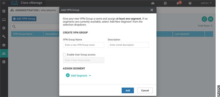
  • Device Specific (indicated by a host icon)

  • Global (indicated by a globe icon)

Configure a T1 Controller

To configure a T1 controller, click the T1 radio button and configure the following parameters. Parameters marked with an asterisk are required to configure an interface.

Table 66.

Parameter Name

Description

Slot*

Enter the number of the slot in which the T1 NIM is installed.

Range: 0 through 6

Framing*

Enter the T1 frame type:

  • esf—Send T1 frames as extended superframes. This is the default.

  • sf—Send T1 frames as superframes. Superframing is sometimes called D4 framing.

Line Code

Select the line encoding to use to send T1 frames:

  • ami—Use alternate mark inversion (AMI) as the linecode. AMI signaling uses frames grouped into superframes.

  • b8zs—Use bipolar 8-zero substitution as the linecode. This is the default. B8ZS uses frames that are grouping into extended superframes

Clock Source

Select the clock source:

  • internal—Use the controller framer as the primary clock.

  • line—Use phase-locked loop (PLL) on the interface. This is the default. When both T1 ports use line clocking and neither port is configured as the primary, by default, port 0 is the primary clock source and port 1 is the secondary clock source.

Line Mode

If you choose the Line clock source, select whether the line is a primary or a secondary line.

Description

Enter a description for the controller.

Channel Group

Enter the number of the channel group. If you do so, you must enter a time slot in the Time Slot field.Range: 0 through 30

Time Slot

Enter the time slot or time slots that are part of the channel group. Range: 1 through 24

Cable Length

Select the cable length to configure the attenuation

  • long—Attenuate the pulse from the transmitter using pulse equalization and line buildout. You can configure a long cable length for cables longer that 660 feet.

  • short—Set the transmission attenuation for cables that are 660 feet or shorter.

There is no default length.

Length

If you specify a value in the Cable Length Field, enter the length of the cable.

For short cables, the length values can be:

  • 110—Length from 0 through 110 feet

  • 220—Length from 111 through 220 feet

  • 330—Length from 221 through 330 feet

  • 440—Length from 331 through 440 feet

  • 550—Length from 441 through 550 feet

  • 660—Length from 551 through 660 feet

For long cables, the length values can be:

  • 0 dB

  • –7.5 dB

  • –15 dB

  • –22.5 dB

To save the feature template, click Save.

Configure an E1 Controller

To configure an E1 controller, click the E1 radio button and configure the following parameters. Parameters marked with an asterisk are required to configure an interface.

Table 67.

Parameter Name

Description

Slot*

Enter the number of the slot in which the E1 NIM is installed.

Range: 0 through 6

Framing*

Enter the E1 frame type:

  • crc4—Use cyclic redundancy check 4 (CRC4). This is the default.

  • no-crc4—Do no use CRC4.

Line Code*

Select the line encoding to use to send E1 frames:

  • ami—Use alternate mark inversion (AMI) as the linecode.

  • hdb3—Use high-density bipolar 3 as the linecode. This is the default.

Clock Source

Select the clock source:

  • internal—Use the controller framer as the primary clock.

  • line—Use phase-locked loop (PLL) on the interface. This is the default.

Line Mode

If you choose the Line clock source, select whether the line is a primary or secondary line. If you configure both a primary and a secondary line, if the primary line fails, the PLL automatically switches to the secondary line. When the PLL on the primary line becomes active again, the PLL automatically switches back to the primary line.

Description

Enter a description for the controller.

Channel Group

To configure the serial WAN on the E1 interface, enter a channel group number.Range: 0 through 30

Time Slot

For a channel group, configure the timeslot.Range: 1 through 31

To save the feature template, click Save.

Release Information

Introduced in Cisco vManage Release 18.1.1.

Cellular Interfaces

To enable LTE connectivity, configure cellular interfaces on a router that has a cellular module. The cellular module provides wireless connectivity over a service provider's cellular network. One use case is to provide wireless connectivity for branch offices.

A cellular network is commonly used as a backup WAN link, to provide network connectivity if all the wired WAN tunnel interfaces on the router become unavailable. You can also use a cellular network as the primary WAN link for a branch office, depending on usage patterns within the branch office and the data rates supported by the core of the service provider's cellular network.

When you configure a cellular interface on a device, you can connect the device to the Internet or another WAN by plugging in the power cable of the device. The device then automatically begins the process of joining the overlay network, by contacting and authenticating with Cisco vBond Orchestrators, Cisco vSmart Controllers, and Cisco vManage systems.

Configure Cellular Interfaces Using vManage

To configure cellular interfaces using vManage templates:

  1. Create a VPN Interface Cellular feature template to configure cellular module parameters, as described in this article.

  2. Create a Cellular Profile template to configure the profiles used by the cellular modem.

  3. Create a VPN feature template to configure VPN parameters.


Note

If your deployment includes devices with cellular interface, you must include cellular controller templates in Cisco vManage, even if these templates are not used.


Create VPN Interface Cellular

  1. In vManage NMS, select the Configuration > Templates screen.

  2. In the Device tab, click Create Template.

  3. From the Create Template drop-down, select From Feature Template.

  4. From the Device Model drop-down, select the type of device for which you are creating the template.

  5. Click the Transport & Management VPN tab or scroll to the Transport & Management VPN section.

  6. Under Additional VPN 0 Templates, click VPN Interface Cellular.
  7. From the VPN Interface Cellular drop-down, click Create Template. The VPN Interface Cellular template form is displayed. The top of the form contains fields for naming the template, and the bottom contains fields for defining VPN Interface Cellular parameters.

  8. In the Template Name field, enter a name for the template. The name can be up to 128 characters and can contain only alphanumeric characters.

  9. In the Template Description field, enter a description of the template. The description can be up to 2048 characters and can contain only alphanumeric characters.

When you first open a feature template, for each parameter that has a default value, the scope is set to Default (indicated by a check mark), and the default setting or value is shown. To change the default or to enter a value, click the scope drop-down to the left of the parameter field.

Configure Basic Cellular Interface Functionality

To configure basic cellular interface functionality, select the Basic Configuration tab and configure the following parameters. Parameters marked with an asterisk are required to configure an interface. You must also configure a tunnel interface for the cellular interface.

Table 68.

Parameter Name

Description

Shutdown*

Click No to enable the interface.

Technology

Cellular technology. The default is lte. Other values are auto and cdma. For ZTP to work, the technology must be auto.

Interface Name*

Enter the name of the interface. It must be cellular0.

Profile ID*

Enter the identification number of the cellular profile. This is the profile identifier that you configure in the Cellular-Profile template.Range: 1 through 15

Description

Enter a description of the cellular interface.

IPv4 Configuration

To configure a static address, click Static and enter an IPv4 address.

To set the interface as a DHCP client so that the interface to receive its IP address from a DHCP server, click Dynamic. You can optionally set the DHCP distance to specify the administrative distance of routes learned from a DHCP server. The default DHCP distance is 1.

IPv6 Configuration

To configure a static address for an interface in VPN 0, click Static and enter an IPv6 address.

To set the interface as a DHCP client so that the interface to receive its IP address from a DHCP server, click Dynamic.You can optionally set the DHCP distance to specify the administrative distance of routes learned from a DHCP server. The default DHCP distance is 1. You can optionally enable DHCP rapid commit, to speed up the assignment of IP addresses.

DHCP Helper

Enter up to four IP addresses for DHCP servers in the network, separated by commas, to have the interface be a DHCP helper. A DHCP helper interface forwards BOOTP (Broadcast) DHCP requests that it receives from the specified DHCP servers.

Block Non-Source IP

Click Yes to have the interface forward traffic only if the source IP address of the traffic matches the interface's IP prefix range.

Bandwidth Upstream

For transmitted traffic, set the bandwidth above which to generate notifications.Range: 1 through (232 / 2) – 1 kbps

Bandwidth Downstream

For received traffic, set the bandwidth above which to generate notifications.Range: 1 through (232 / 2) – 1 kbps

IP MTU*

Enter 1428 to set the MTU size, in bytes. This value must be 1428. You cannot use a different value.

To save the feature template, click Save.

CLI equivalent:

Create a Tunnel Interface

To configure an interface in VPN 0 to be a WAN transport connection, you must configure a tunnel interface on the cellular interface. The tunnel, which provides security from attacks, is used to send the phone number. At a minimum, select On and select a color for the interface, as described in the previous section. You can generally accept the system defaults for the remainder of the tunnel interface settings.

To configure a tunnel interface, select the Tunnel tab, set Tunnel Interface to On, and configure the following parameters. Parameters marked with an asterisk are required to configure a cellular interface.

Table 69.

Parameter Name

Description

Tunnel Interface*

Click On to create a tunnel interface.

Color*

Select a color for the TLOC. The color typically used for cellular interface tunnels is lte.

Control Connection

The default is On, which establishes a control connection for the TLOC. If the router has multiple TLOCs, click No to have a tunnel not establish a TLOC.

Maximum Control Connections

Set the maximum number of vSmart controllers that the WAN tunnel interface can connect to. To have the tunnel establish no control connections, set the number to 0.Range: 0 through 8

Default: 2

vBond As STUN Server

Click On to enable Session Traversal Utilities for NAT (STUN) to allow the tunnel interface to discover its public IP address and port number when the router is located behind a NAT.

Exclude Control Group List

Set the identifiers of one or more vSmart controller groups that this tunnel is not allows to establish control connections with.

Range: 0 through 100

vManage Connection Preference

Set the preference for using the tunnel to exchange control traffic with the vManage NMS.

Range: 0 through 9

Default: 5

Low-Bandwidth Link

Click On to set the tunnel interface as a low-bandwidth link.

Default: Off

Allow Service

Click On or Off for each service to allow or disallow the service on the cellular interface.

To configure additional tunnel interface parameters, click Advanced Options and configure the following parameters:

Table 70.

Parameter Name

Description

GRE

Use GRE encapsulation on the tunnel interface. By default, GRE is disabled.

If you select both IPsec and GRE encapsulations, two TLOCs are created for the tunnel interface that have the same IP addresses and colors, but that differ by their encapsulation.

IPsec

Use IPsec encapsulation on the tunnel interface. By default, IPsec is enabled.

If you select both IPsec and GRE encapsulations, two TLOCs are created for the tunnel interface that have the same IP addresses and colors, but that differ by their encapsulation.

IPsec Preference

Enter a value to set the preference for directing traffic to the tunnel. A higher value is preferred over a lower value.Range: 0 through 4294967295Default: 0

IPsec Weight

Enter a weight to use to balance traffic across multiple TLOCs. A higher value sends more traffic to the tunnel.Range: 1 through 255Default: 1

Carrier

Select the carrier name or private network identifier to associate with the tunnel.Values: carrier1, carrier2, carrier3, carrier4, carrier5, carrier6, carrier7, carrier8, defaultDefault: default

Bind Loopback Tunnel

Enter the name of a physical interface to bind to a loopback interface. The interface name has the format ge slot/port.

Last-Resort Circuit

Use the tunnel interface as the circuit of last resort

NAT Refresh Interval

Set the interval between NAT refresh packets sent on a DTLS or TLS WAN transport connection.Range: 1 through 60 secondsDefault: 5 seconds

Hello Interval

Enter the interval between Hello packets sent on a DTLS or TLS WAN transport connection.Range: 100 through 10000 millisecondsDefault: 1000 milliseconds (1 second)

Hello Tolerance

Enter the time to wait for a Hello packet on a DTLS or TLS WAN transport connection before declaring that transport tunnel to be down.

Range: 12 through 60 secondsDefault: 12 seconds

To save the feature template, click Save.

CLI equivalent:

Configure the Cellular Interface as a NAT Device

To configure a cellular interface to act as a NAT device for applications such as port forwarding, select the NAT tab, click On and configure the following parameters:

Table 71. Configure the Cellular Interface as a NAT Device

Parameter Name

Description

NAT

Click On to have the interface act as a NAT device.

Refresh Mode

Select how NAT mappings are refreshed, either outbound or bidirectional (outbound and inbound).Default: Outbound

UDP Timeout

Specify when NAT translations over UDP sessions time out.Range: 1 through 65536 minutesDefault: 1 minute

TCP Timeout

Specify when NAT translations over TCP sessions time out.Range: 1 through 65536 minutesDefault: 60 minutes (1 hour)

Block ICMP

Select On to block inbound ICMP error messages. By default, a router acting as a NAT device receives these error messages.Default: Off

Respond to Ping

Select On to have the router respond to ping requests to the NAT interface's IP address that are received from the public side of the connection.

To create a port forwarding rule, click Add New Port Forwarding Rule and configure the following parameters. You can define up to 128 port-forwarding rules to allow requests from an external network to reach devices on the internal network.

Table 72.

Parameter Name

Description

Port Start Range

Enter a port number to define the port or first port in the range of interest.Range: 0 through 65535

Port End Range

Enter the same port number to apply port forwarding to a single port, or enter a larger number to apply it to a range of ports.Range: 0 through 65535

Protocol

Select the protocol to which to apply the port-forwarding rule, either TCP or UDP. To match the same ports for both TCP and UDP traffic, configure two rules.

VPN

Specify the private VPN in which the internal server resides. This VPN is one of the VPN identifiers in the overlay network.Range: 0 through 65530

Private IP

Specify the IP address of the internal server to which to direct traffic that matches the port-forwarding rule.

To save a port forwarding rule, click Add.

To save the feature template, click Save.

CLI equivalent:

Apply Access Lists

To configure a shaping rate to a cellular interface and to apply a QoS map, a rewrite rule, access lists, and policers to a router interface, select the ACL/QoS tab and configure the following parameters:

Table 73. Access Lists Parameters

Parameter Name

Description

Shaping rate

Configure the aggreate traffic transmission rate on the interface to be less than line rate, in kilobits per second (kbps).

QoS map

Specify the name of the QoS map to apply to packets being transmitted out the interface.

Rewrite rule

Click On, and specify the name of the rewrite rule to apply on the interface.

Ingress ACL – IPv4

Click On, and specify the name of an IPv4 access list to packets being received on the interface.

Egress ACL– IPv4

Click On, and specify the name of an IPv4 access list to packets being transmitted on the interface.

Ingress ACL – IPv6

Click On, and specify the name of an IPv6 access list to packets being received on the interface.

Egress ACL– IPv6

Click On, and specify the name of an IPv6 access list to packets being transmitted on the interface.

Ingress policer

Click On, and specify the name of the policer to apply to packets being received on the interface.

Egress policer

Click On, and specify the name of the policer to apply to packets being transmitted on the interface.

To save the feature template, click Save.

CLI equivalent:

Add ARP Table Entries

To configure static Address Resolution Protocol (ARP) table entries on the interface, select the ARP tab. Then click Add New ARP and configure the following parameters:

Table 74.

Parameter Name

Description

IP Address

Enter the IP address for the ARP entry in dotted decimal notation or as a fully qualified host name.

MAC Address

Enter the MAC address in colon-separated hexadecimal notation.

To save the ARP configuration, click Add.

To save the feature template, click Save.

CLI equivalent:

Configure Other Interface Properties

To configure other interface properties, select the Advanced tab and configure the following parameters.

Table 75. Cellular Interfaces Advanced Parameters

Parameter Name

Description

PMTU Discovery

Click On to enable path MTU discovery on the interface, to allow the router to determine the largest MTU size supported without requiring packet fragmentation.

TCP MSS

Specify the maximum segment size (MSS) of TPC SYN packets passing through the router. By default, the MSS is dynamically adjusted based on the interface or tunnel MTU such that TCP SYN packets are never fragmented.Range: 552 to 1460 bytesDefault: None

Clear-Dont-Fragment

Click On to clear the Don't Fragment (DF) bit in the IPv4 packet header for packets being transmitted out the interface. When the DF bit is cleared, packets larger than that interface's MTU are fragmented before being sent.

Static Ingress QoS

Select a queue number to use for incoming traffic.Range: 0 through 7

ARP Timeout

Specify how long it takes for a dynamically learned ARP entry to time out.Range: 0 through 2678400 seconds (744 hours)Default: 1200 seconds (20 minutes)

Autonegotiate

Click Off to turn off autonegotiation. By default, an interface runs in autonegotiation mode.

TLOC Extension

Enter the name of a physical interface on the same router that connects to the WAN transport. This configuration then binds this service-side interface to the WAN transport. A second router at the same site that itself has no direct connection to the WAN (generally because the site has only a single WAN connection) and that connects to this service-side interface is then provided with a connection to the WAN.

Tracker

Enter the name of a tracker to track the status of transport interfaces that connect to the internet.

ICMP Redirect

Click Disable to disable ICMP redirect messages on the interface. By default, an interface allows ICMP redirect messages.

To save the feature template, click Save.

CLI equivalent:

Release Information

Introduced in vManage NMS in Release 16.1. In Release 16.2, add circuit of last resort and its associated hold time. In Release 16.3, add support for IPv6. In Release 17.2.2, add support for tracker interface status. In Release 18.2, add support for disabling ICMP redirect messages.

Configure Cellular Interfaces Using CLI

interface Cellular0/2/0
   description Cellular interface
   no shutdown
   ip address negotiated
   ip mtu 1428
   mtu 1500
  exit

  controller Cellular 0/2/0
   lte sim max-retry 1
   lte failovertimer 7
   profile id 1 apn Broadband authentication none pdn-type ipv4

Low-bandwidth Link Optimization

For low-bandwidth links, such as LTE cellular links, that are part of the overlay network, SD-WAN can reduce the amount of bandwidth used for control plane traffic. This can be helpful to reduce charges for cellular traffic, and to leave more bandwidth available for data traffic.

BFD Fault Detection Uses Bandwidth

Bidirectional Forwarding Detection (BFD) is a network protocol that detects faults in the ability to forward traffic between two nodes in a network. The fault detection that BFD provides is a valuable component of routing management.

BFD operates by establishing sessions between nodes in a network that carry data traffic. These sessions use a handshake procedure to monitor connectivity. This produces a significant amount of control plane traffic.

In the BFD “asynchronous mode” handshake procedure, the two nodes in a BFD session send ECHO requests to each other periodically. If no response is received after a request, a node considers the link to be down and reports this. Parameters such as transmission timer (Hello interval) and detection timer govern this mode.

Low Bandwidth Link Option Reduces Traffic

For low-bandwidth links, it is worthwhile to reduce this control traffic, while preserving BFD functionality. Using the low-bandwidth-link option reduces the BFD handshake traffic by almost half.

With this option enabled, BFD designates one node within a BFD session as primary node and the other node as subordinate node. The primary node continues to send ECHO requests and listen for responses, as usual. The subordinate node does not send ECHO requests, but sends responses to requests.

If the primary node sends an ECHO request and does not receive a response, the reason may be that either one of the following:

  • Transmission of the request failed.

  • Transmission of the response failed.

The primary node does not need to distinguish between these possibilities. If the primary node does not receive a response within a specified detection time, it determines that the link between the nodes is down and sends a State Down message to the subordinate node.

Connection Statistics in Low-bandwidth-link Mode

With the low bandwidth link option, SD-WAN uses a streamlined logic to measure packet loss, latency, and jitter.

Statistic

Mechanism in low-bandwidth-link mode

Packet loss

BFD uses two mechanisms together to track packet loss.

  • When the primary node fails to receive a response to an ECHO request, it sends a “Last Lost” message in its next ECHO request. When the subordinate node receives this, it increments its count of lost packets.

  • When the subordinate node fails to receive an ECHO request for longer than a configured interval, it concludes that the ECHO request was lost, and increments its count of lost packets.

Combining these two enables SD-WAN to measure packet loss.

Latency

The primary node measures the round-trip latency between sending an ECHO request and receiving a response.

Jitter

The primary node measures the variability of latency over time.

Using this primary/subordinate hierarchical model, and the logic described above, SD-WAN can collect connection statistics using less control plane traffic.

Interoperability: Cisco vEdge and Cisco XE SD-WAN Devices

A network may include Cisco vEdge and Cisco XE SD-WAN devices. Low-bandwidth-link mode operates on both classes of devices, and the two types of devices can operate together in a BFD session.

Configuring Low-Bandwidth Link

It is possible to use the low-bandwidth link option when configuring any interface that allows tunneling. When configuring interfaces using vManage, the low-bandwidth link appears as an option in the Tunnel section of WAN feature templates, such as VPN Interface Cellular or VPN Interface PPP.

WiFi Radio

Use the WiFi Radio template for all devices that support wireless LANs (WLANs).

To configure WLAN radio parameters using Cisco vManage templates:

  1. Create a WiFi Radio template to configure WLAN radio parameters, as described in this article.

  2. Create a Wifi SSID template to configure an SSID and related parameters.

Create WLAN Feature Template

  1. In Cisco vManage, select the Configuration > Templatesscreen.

  2. In the Device tab, click Create Template.

  3. From the Create Template drop-down, select From Feature Template.

  4. From the Device Model drop-down, select the device model that supports wireless LANs (WLANs).

  5. Click the WLAN tab, or scroll to the WLAN section.

  6. From the WiFi Radio drop-down, click Create Template. The WiFi Radio template form is displayed. The top of the form contains fields for naming the template, and the bottom contains fields for defining WiFi Radio parameters.
  7. In the Template Name field, enter a name for the template. The name can be up to 128 characters and can contain only alphanumeric characters.

  8. In the Template Description field, enter a description of the template. The description can be up to 2048 characters and can contain only alphanumeric characters.

When you first open a feature template, for each parameter that has a default value, the scope is set to Default (indicated by a check mark), and the default setting or value is shown. To change the default or to enter a value, click the scope drop-down to the left of the parameter field.

Configure the WLAN Radio Frequency

To configure the WLAN radio frequency, in the Basic Configuration tab, configure the following parameters. Parameters marked with an asterisk are required to configure the radio.

Table 76.

Parameter Name

Description

Select Radio*

Select the radio band. It can be 2.4 GHz or 5 GHz.

Country*

Select the country where the router is installed.

Channel Bandwidth

Select the IEEE 802.11n and 802.11ac channel bandwidth. For a 5-GHz radio band, the default value is 80 MHz, and for 2.4 GHz, the default is 20 MHz.

Channel

Select the radio channel. The default is "auto", which automatically selects the best channel. For 5-GHz radio bands, you can configure dynamic frequency selection (DFS) channels.

Guard Interval

Select the guard interval. For a 5-GHz radio band, the default value is the short guard interval (SGI) of 400 ns, and for 2.4 GHz, the default is 800 ns.

To save the feature template, click Save.

Release Information

Introduced in vManage NMS Release 16.3.

WiFi SSID

You can use the WiFi SSID template for all devices that support wireless LANs (WLANs)

To configure SSIDs on the WLAN radio using vManage templates:

  1. Create a WiFi SSID template to configure the VAP interfaces to use as SSIDs, as described in this article.

  2. Create a WiFi Radio template to configure WLAN radio parameters.

  3. Create a Bridge template to assign the VAP interface to a bridging domain.

  4. Create a device template that incorporates the WiFi Radio feature template and the Wifi SSID feature template.

Navigate to the Template Screen and Name the Template

  1. In Cisco vManage, select the Configuration ► Templates screen.

  2. In the Device tab, click Create Template.

  3. From the Create Template drop-down, select From Feature Template.

  4. From the Device Model drop-down, select a device that supports wireless LANs (WLANs).

  5. Click the WLAN tab located directly beneath the Description field, or scroll to the WLAN section.

  6. Under Additional WiFi Radio Templates, located to the right of the screen, click WiFi SSID.
  7. From the WiFi SSID drop-down, click Create Template. The WiFi SSID template form is displayed. The top of the form contains fields for naming the template, and the bottom contains fields for defining WiFi SSID parameters.

  8. In the Template Name field, enter a name for the template. The name can be up to 128 characters and can contain only alphanumeric characters.

  9. In the Template Description field, enter a description of the template. The description can be up to 2048 characters and can contain only alphanumeric characters.

When you first open a feature template, for each parameter that has a default value, the scope is set to Default (indicated by a check mark), and the default setting or value is shown. To change the default or to enter a value, click the scope drop-down to the left of the parameter field.

WLAN SSID Configuration

To configure SSIDs on a device, configure the following parameters in the Basic Configuration tab. Parameters marked with an asterisk are required to configure the SSIDs.

Table 77.

Parameter Name

Description

Interface Name*

Select the VAP interface name.

Shutdown*

Click No to enable the interface.

Description (optional)

Enter a description for the interface.

SSID*

Enter the name of the SSID. It can be a string from 4 through 32 characters. The SSID must be unique.

You can configure up to four SSIDs.

Each SSID is called a virtual access point (VAP) interface. To a client, each VAP interfaces appears as a different access point (AP) with its own SSID. To provide access to different networks, assign each VAP to a different VLAN.

Maximum Clients

Enter the maximum number of clients allowed to connect to the WLAN.Range: 1 through 50Default: 25

Data Security

Select the security type to enable user authentication or enterprise WPA security.

For user authentication, select from WPA Personal, WPA/WPA2 Personal, or WPA2 Personal, and then enter a clear text or an AES-encrypted key.

For enterprise security, select from WPA Enterprise, WPA/WPA2 Enterprise, or WPA2 Enterprise, and then enter a RADIUS server tag.

RADIUS Server

If you select one of the enterprise security methods based on using a RADIUS authentication server, enter the RADIUS server tag.

WPA Personal Key

If you select one of the personal security methods based on preshared keys, enter either a clear text or an AES-encrypted password.

Management Security

If you select one of the WPA2 security methods, select the encryption of management frames to be none, optional, or required.

To save the feature template, click Save.

Release Information

Introduced in Cisco vManage Release 16.3.