Overview

The Cisco Catalyst 8200 Series Edge Platforms are best-of-breed, 5G-ready, cloud edge platforms designed for accelerated services, multi-layer security, cloud-native agility, and edge intelligence to accelerate your journey to cloud.

Cisco Catalyst 8200 Series Edge Platforms with Cisco IOS XE SD-WAN Software deliver Cisco’s secure, cloud-scale SD-WAN solution for the branch. The Cisco Catalyst 8200 Series Edge Platforms is built for high performance and integrated SD-WAN Services along with flexibility to deliver security and networking services together from the cloud or on premises. It provides higher WAN port density and a redundant power supply capability. The Cisco Catalyst 8200 Series Edge Platforms have a wide variety of interface options to choose from—ranging from lower and higher module density with backward compatibility to a variety of existing WAN, LTE, voice, and compute modules. Powered by Cisco IOS XE, fully programmable software architecture, and API support, these platforms can facilitate automation at scale to achieve zero-touch IT capability while migrating workloads to the cloud. The Cisco Catalyst 8200 Series Edge Platforms also come with Trustworthy Solutions 2.0 infrastructure that secures the platforms against threats and vulnerabilities with integrity verification and remediation of threats.

The Cisco Catalyst 8200 Series Edge Platforms are well suited for medium-sized and large enterprise branch offices for high WAN IPSec performance with integrated SD-WAN services.

Cisco Catalyst 8200 Series Edge Platforms target these use cases:

  • Enterprise Branch office, Managed Service Provide CPE, Internet Gateway for DIA, SASE cloud platform with SD-WAN

  • Next-generation of Software Defined (SD) Branch routing platforms

For more information on the features and specifications, refer to the Cisco Catalyst 8200 Series Edge Platforms datasheet.


Note


Sections in this documentation apply to all models of Cisco Catalyst 8200 Series Edge Platforms unless a reference to a specific model is made explicitly.

This chapter contains the following sections:

Chassis Views

This section contains views of the Power-input and I/O sides of the Cisco Catalyst 8200 Series Edge Platforms, showing the locations of power and signal interfaces, module slots, status indicators, and chassis identification labels:

Cisco Catalyst 8200 Series Edge Platforms are available in these models:

  • C8200-1N-4T

  • C8200L-1N-4T


Note


N=Network Interface Modue, and T=Gigabit Ethernet


Power-input and I/O sides

Figure 1. Cisco 8200 Series Chassis - I/O Side
Table 1. I/O Side

1

Logo

2

Status LEDs

3

USB

4

RJ-45 ports GE0/0/0-0/0/1

5

Gigabit Ethernet ports GE0/0/2 - 0/0/3

(SFP)

6

LTE module (PIM)

7

NIM Module

8

Kensington lock

9

RJ-45 Console

10

M.2 USB/NVMe storage

11

RFID (Provisionable)

Figure 2. Cisco 8200 Series Chassis - Power-input Side
Table 2. Power-input Side

1

Switch

2

AC power socket

3

PoE Adapter

4

Fan

5

Ground lug securing location

For detailed information on LEDs, see the section on LED indicators.

Platform Summary

The figure below shows the internal view of Cisco Catalyst 8200 Series Edge Platforms with components and module locations.
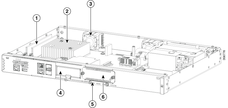
Figure 3. Platform Summary of Cisco 8200 Series Edge Platforms

1

DIMMs

2

CPU

3

Fan

4

PIM slot

5

M.2 card slot

6

NIM slot

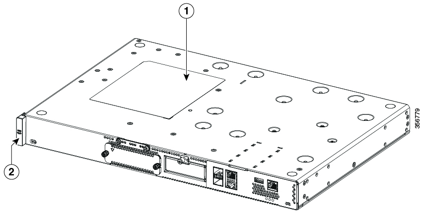
Location of labels

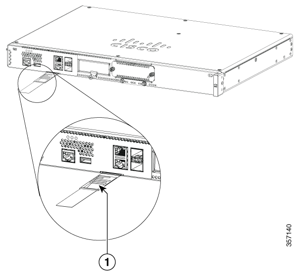
The figure below shows the location of the labels on the Cisco Catalyst 8200 Series Edge Platforms. Labels are located at the same location on all the Cisco Catalyst 8200 Series Edge Platforms.

The Serial number (SN), Common language equipment identifier (CLEI), Top Assembly Number (TAN), Product ID (PID), PID version ID (VID), and Quick response (QR) code are printed on a label on the back of the platform or on a label tray located on the chassis.


Note


The RFID tags on the devices are pre-fitted and does not come with spare RFID tags.


Figure 4. Label Location on a Cisco 8200 Series Edge Platforms

1

Compliance label

2

RFID

Locate Product Identification Details

Software License

The serial number (SN), product ID (PID), version ID (VID), and Common Language Equipment Identifier (CLEI) are printed on a label on the bottom of the device or on the label tray.

To obtain a software license, you need the unique device identifier (UDI) of the device where the license is to be installed.

The UDI has two main components:

  • Product ID (PID)

  • Serial number (SN)

The UDI can be viewed using the show license udi command in privileged Exec mode in Cisco Internet Operating System (IOS) software.

1

Label tray

Hardware Features of Cisco Catalyst 8200 Series Edge Platforms

This section describes the hardware features of Cisco Catalyst 8200 Series Edge Platforms.

Built-In Interface Ports

The Cisco Catalyst 8200 Series Edge Platforms have multiple 10/100/1000 front panel ports and Small Form Pluggables.

GE or SFP Ports

The following GE and SFP ports are available on the Cisco Catalyst 8200 Series Edge Platforms:

GE Ports

The GE RJ-45 copper interface ports support 10BASE-T, 100BASE-TX, and 1000BASE-T.

SFP Ports

The small-form-factor pluggable (SFP) ports support 1Gbps SFP modules.

Removable and Interchangeable Modules and Cards

Network Interface Modules (NIMs), Pluggable Interface Modules (PIMs) and M.2 USB/NVMe storage fit into external slots and can be removed or replaced without opening the chassis.

External Slots

  • Network Interface Modules (NIMs)

  • Pluggable Interface Modules (PIMs)

  • M.2 USB/NVMe storage


Note


The LTE Pluggable Interface Module interfaces with the host CPU through the USB3.0 interface. The host then accesses the LTE related signals through the I2C interface of the pluggable module.


Internal Slots

  • Memory

See the Cisco Catalyst 8200 Series Edge Platforms product page on cisco.com for a list of supported modules and interface cards.

Memory

Cisco Catalyst 8200 Series Edge Platforms contain DIMMs that store running configuration and routing tables, and are used for packet buffering by the network interfaces.

  • Boot/NVRAM—Stores the bootstrap program (ROM monitor) and the configuration register. The boot/NVRAM is not serviceable.

  • Internal memory—Internal bootflash memory

  • Removable M.2 card—Available in 16GB (default), 32GB M.2 USB, 600GB M.2 NVMe SSD and 2TB M.2 NVMe.

  • DRAM options

    • 1x 8GB DDR4 (default)

    • 1x 16GB DDR4 (upgrade)

    • 1x 32GB DDR4 (upgrade)


    Note


    The default DRAM for C8200L-1N-4T is 4GB. For Cisco SD-WAN, we recommend a minimum of 8GB of memory.


Power Supply

The Cisco Catalyst 8200 Series Edge Platforms have an internal Power supply. The appropriate AC-cord is provided with the product to connect to the AC power socket. Optional PoE is available with a PoE adapter. Refer the Figure 2 for the power connection locations (AC power socket and PoE adapter).

LEDs for Cisco Catalyst 8200 Series Edge Platforms

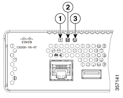
Figure 5. Front (I/O) Side LED Status Indicators
Table 3. LEDs Indicators

LED

Color

Description

1

PSU

Green/Amber

Power Supply Status

Off: The system is powered off

Green: All installed PSUs are operating correctly

2

STATUS

Green/Amber/Red

System Status

Red: The system is booting

Red Blinking Red: The system has failed a hardware integrity error

Yellow: Rommon has completed booting and system at Rommon prompt or booting platform software.

Green: Normal System Operation

3

ENV

Green/Amber/Red

Environmental Status

Off: Monitor is not active.

Red: The system has detected a critical overcurrent event and may shut down.

Blinking Yellow: One or more temperature sensors in the system are outside the acceptable range.

Yellow: One or more fans in the system are outside the acceptable range.

Green: All temperature sensors and fans in the system are within acceptable range.

LINK

Green

RJ-45 Management Ethernet Link LED

Off: No link

Green: Ethernet cable present and link established with other side

SPEED

Green

RJ-45 Management Ethernet Speed LED

Off: No Link

Blinking Green: blink frequency indicates port speed:

1 blink – 10Mbps link speed

2 blinks – 100Mbps link speed

3 blinks – 1000Mbps link speed

SFP EN

Green

SFP Enable LED

Off: Not present

Green: The SFP is supported and no faults.

Amber: The SFP is not supported or is in a faulty state

SFP LINK

Green

SFPs Link LED

Off: No Link (or not present)

Green: Link established

Fans, Ventilation, and Airflow

Chassis Ventilation

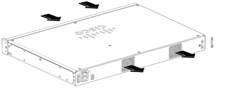
The chassis temperature is regulated with internal fans. An onboard temperature sensor and pressure sensor control the fans speed. The fans are always on when the device is powered on. Under all conditions, the fans operate at the slowest speed possible to conserve power and reduce noise. When necessary, the fans operate at higher speeds under conditions of higher ambient temperature and altitude.

Figure 6. Airflow of C8200 Series Edge Platforms

Slots, Subslots-Bay, Ports, and Interfaces

The Cisco Catalyst 8200 Series Edge Platforms support interface modules: Network Modules (NIMs) and Pluggable Interface Modules (PIMs).

In all cases, the device designates its interfaces using a 3-tuple notation that lists the slot, bay, and port. The 3-tuple value is zero based. An example of a 3-tuple is 0/1/2. This refers to slot 0, the second bay in slot 0 (the first bay is 0 so the second bay is 1), and the third port in bay 1. See the following table for more examples.

Table 4. Slot, Subslot-Bay and Port Numbering

3-Tuple Example

Slot

Bay

Port

0/1/2

0

2nd

3rd

0/0/1

0

1st

2nd

1/1/1

1

2nd

2nd

  • Slots and bays are numbered from the left to the right, and from the top to the bottom.

  • There is one USB port-USB0. They do not have slot or bay numbers.


Note


USB0 can be used to insert flash drives.


Slot Numbering

Slots are numbered 0, 1, and 2.

About Slot 0

The following are the main features of Slot 0:

  • Slot 0 is reserved for integrated ports and NIMs.

Subslot and Bay Numbering
  • Integrated devices, also known as integrated ports or FPGEs, and NIMs reside in a fixed section of bay 0.

  • Motherboard NIMs bays start at bay 1 because the integrated devices and integrated NIMs take up bay 0.