Install Internal Components and Field Replaceable Units

This document describes how to install internal components and field replaceable units (FRUs) in the Cisco Catalyst 8200 Series Edge Platforms. The installation information is contained in these sections:

Safety Warnings


Warning


High touch/leakage current – Permanently connected protective earth ground is essential before connecting to telecommunication network.


Warning


Class 1 laser product. Statement 1008


Warning


To reduce the risk of electric shock, the chassis of this equipment needs to be connected to permanent earth ground during normal use. Statement 0445

Warning


To reduce risk of electric shock and fire, a readily accessible two-poled disconnect device must be incorporated in the fixed wiring. Statement 1022

Warning


Only trained and qualified personnel should be allowed to install, replace, or service this equipment. Statement 1030

Warning


Invisible laser radiation may be emitted from disconnected fibers or connectors. Do not stare into beams or view directly with optical instruments. Statement 1051


Warning


Invisible laser radiation may be emitted from the end of the unterminated fiber cable or connector. Do not view directly with optical instruments. Viewing the laser output with certain optical instruments (for example, eye loupes, magnifiers, and microscopes) within a distance of 100 mm may pose an eye hazard. Statement 1056


Warning


Only instructed person or skilled person should be allowed to install, replace, or service this equipment. Refer to statement 1089 for description of skilled person.


Warning


Only instructed person or skilled person should be allowed to install, replace, or service this equipment. Refer to statement 1089 for description of skilled person. Statement 1090


Warning


Only instructed person or skilled person should be allowed to install, replace, or service this equipment. Refer to statement 1089 for description of skilled person. Statement 1091


Warning


Pluggable optical modules comply with IEC 60825-1 Ed. 3 and 21 CFR 1040.10 and 1040.11 with or without exception for conformance with IEC 60825-1 Ed. 3 as described in Laser Notice No. 56, dated May 8, 2019.. Statement 1255


Locate and Access Internal Components

The figures below show the locations of internal components on the motherboard. Internal modules include DIMMs on Cisco Catalyst 8200 Series Edge Platforms.

To access the internal components on the device, you must first remove the chassis cover. For instructions on how to remove and replace the chassis cover on the device, see the sections on Install and Remove Chassis Covers.

Figure 1. Internal Component Location in the Cisco 8200 Series Chassis

Sl. No

Modules

1

DIMMs

Remove and Replace the Chassis Cover

The Cisco Catalyst 8200 Series Edge Platforms have removable covers. Before removing the cover, do these steps:

  • Do not run the device with the cover off. Doing so can cause the chassis to overheat very quickly.

  • Before opening the unit, disconnect the telephone-network cables to avoid contact with telephone-network voltages. Statement 1041.

  • Disconnect all power cables.

  • Remove the device from the rack

Use a number-2 Phillips screwdriver to perform the following tasks.

Remove the Cover

To remove the cover, perform the following steps.

Procedure

Step 1

Read the Safety Warnings and disconnect the power supply before you perform any module replacement.

Step 2

Confirm the device is turned off and disconnected from the power supply or power supplies. If a redundant power is used, disconnect from the redundant power supply.

Step 3

Place the chassis on a flat surface.

Step 4

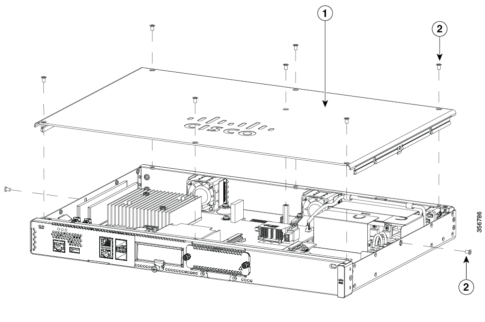
For Catalyst 8200 Series Edge Platforms, remove the 9 cover screws.

Step 5

Lift the cover straight up.


Replace the Cover

To replace the cover, perform the following steps.

Procedure

Step 1

Place the chassis on a flat surface.

Step 2

Drop the cover straight down and ensure that the side flanges insert into the chassis. Care should be taken to not damage the EMC Gaskets.

Step 3

For Catalyst 8200 Series Edge Platforms, install the 9 cover screws.

Figure 2. Install the Cover on the Cisco 8200 Series Chassis

1

Cover

2

Screws


Remove and Replace DDR DIMMs

To access the DIMMs, you must remove the chassis cover as described in the Access and Install Modules section.


Caution


Always wear an ESD-preventive wrist strap and ensure that it makes good contact with your skin when you remove or install DIMMs. Connect the equipment end of the wrist strap to the metal part of the chassis.


Caution


Handle DIMMs by the edges only. DIMMs are ESD-sensitive components and can be damaged by mishandling.


Locate and Orient DIMM

DIMMs have a polarization notch on the mating edge to prevent incorrect insertion. The following image shows the polarization notch on a DIMM.

Figure 3. DIMM Showing Polarization Notch

1

Polarization notch

Remove a DIMM

Follow these steps to remove a DIMM:

Procedure


Step 1

Read the Safety Warnings section and disconnect the power supply before you perform any module replacement.

Step 2

If the cover is not already removed, remove the chassis cover.

Step 3

Locate the DIMM module to find the DIMM sockets on the chassis.

Step 4

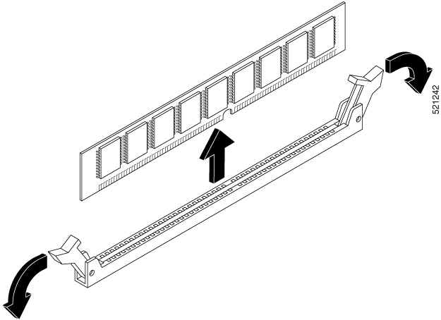
Rotate DIMM connector handles downwards to extract the DIMM module.

Figure 4. Remove a DIMM

Install a DIMM

Follow these steps to install a DIMM on the Cisco Catalyst 8200 Series Edge Platforms.

Procedure


Step 1

Read the Safety Warnings section and disconnect the power supply before you perform any DIMM replacement.

Step 2

If the cover is not already removed, remove the chassis cover.

Step 3

Locate the DIMM module to find the DIMM sockets on the device.

Step 4

Ensure that both latches on the DIMM connector are in the open position.

Step 5

Orient the DIMM so that the polarization notch lines up with the polarization key on the connector.

Figure 5. DIMM Showing Polarization Notch

Step 6

Insert the DIMM into the connector one side at a time.

Step 7

Rotate the connector handles upward and click into place.

Step 8

Reinstall the chassis cover.

Figure 6. Install a DIMM

Step 9

Replace the chassis cover.


Install and Remove SFP Modules

Before you begin

See the Cisco Catalyst 8200 Series Edge Platforms's datasheet on cisco.com for a list of supported SFP modules. Use only supported SFP modules on the platform.


Warning


Class 1 laser product. Statement 1008
  • Do not remove the dust plugs from the SFP modules or the rubber caps from the fiber-optic cable until you are ready to connect the cable. The plugs and caps protect the module ports and cables from contamination and ambient light.

  • Removing and installing an SFP module can shorten its useful life. Do not remove and insert any SFP module more often than is necessary.

  • To prevent ESD damage, follow your normal board and component handling procedures when connecting cables to the switch and other devices.

  • When you insert several SFP modules in multiple ports, wait for 5 seconds between inserting each SFP. This will prevent the ports from going into error disabled mode. Similarly, when you remove an SFP from a port, wait for 5 seconds before reinserting it.

Procedure


Step 1

Attach an ESD-preventive wrist strap to your wrist and to an earth ground surface.

Step 2

Find the send (TX) and receive (RX) markings that identify the top of the SFP module.

On some SFP modules, the send and receive (TX and RX) markings might be shown by arrows that show the direction of the connection.

Step 3

If the SFP module has a bale-clasp latch, move it to the open, unlocked position.

Step 4

Align the module in front of the slot opening, and push until you feel the connector snap into place.

Step 5

If the module has a bale-clasp latch, close it to lock the SFP module in place.

Step 6

Remove the SFP dust plugs and save.

Step 7

Connect the SFP cables.


Laser Safety Guidelines

Optical Small-Form Pluggable (SFPs) use a small laser to generate the fiber-optic signal. Keep the optical transmit and receive ports covered whenever a cable is not connected to the port.


Warning


Invisible laser radiation may be emitted from disconnected fibers or connectors. Do not stare into beams or view directly with optical instruments. Statement 1051

Warning


Ultimate disposal of this product should be handled according to all national laws and regulations. Statement 1040

Warning


Pluggable optical modules comply with IEC 60825-1 Ed. 3 and 21 CFR 1040.10 and 1040.11 with or without exception for conformance with IEC 60825-1 Ed. 3 as described in Laser Notice No. 56, dated May 8, 2019. Statement 1255.

To install an SFP module in your device, perform these steps:

Procedure


Step 1

Read the Safety Warnings section and disconnect the power supply before you perform any module replacement.

Step 2

Slide the SFP into the device connector until it locks into position

Tip


If the SFP uses a bale-clasp latch (see Laser Safety Guidelines section, the handle should be on top of the SFP module.

Figure 7. Install a Small-Form Pluggable Module

Caution


Do not remove the optical port plugs from the SFP until you are ready to connect cabling.

Step 3

Connect the network cable to the SFP module.


Remove Small Form Pluggable Modules

Follow these steps to remove a Small Form Pluggable (SFP) from the device:

Procedure


Step 1

Read the Safety Warnings section and disconnect the power supply before you perform any module replacement.

Step 2

Disconnect all cables from the SFP.

Warning

 
Invisible laser radiation may be emitted from disconnected fibers or connectors. Do not stare into beams or view directly with optical instruments. Statement 1051

Caution

 
The latching mechanism used on many SFPs locks the SFP into place when cables are connected. Do not pull on the cabling in an attempt to remove the SFP.

Step 3

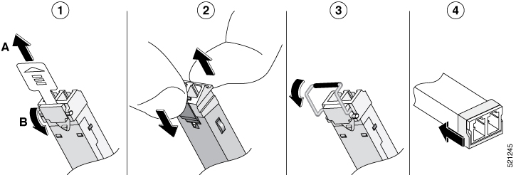
Disconnect the SFP latch.

Note

 
SFP modules use various latch designs to secure the module in the SFP port. Latch designs are not linked to SFP model or technology type. For information on the SFP technology type and model, see the label on the side of the SFP.
Figure 8. Disconnecting SFP Latch Mechanisms

1

Sliding latch

3

Bale-clasp latch

2

Swing and slide latch

4

Plastic collar latch

Tip


Use a pen, screwdriver, or other small straight tool to gently release a bale-clasp handle if you cannot reach it with your fingers.

Step 4

Grasp the SFP on both sides and remove it from the device.


Remove and Replace the USB Flash Token Memory Stick

The Cisco Catalyst 8200 Series Edge Platforms contain ports for a USB memory stick to store Cisco configurations or Cisco IOS XE consolidated packages.


Caution


Do not remove a USB Flash memory module when issuing some file access command or a read/write operation to the Flash memory module when it is processing. The router might reload or the USB Flash memory module can be damaged. You can check to see if the USB activity LED on the router front panel is flashing, prior to the removal of the USB device


To install, remove a USB memory stick from the device, follow these steps:

Procedure


Step 1

Place the USB stick into the USB port.

Step 2

Type-C memory sticks are supported on USB port 1 and type-C memory can be inserted in any direction. Type-A memory sticks are supported on USB port 0 and it must be oriented correctly to allow for proper insertion.

Note

 
A sample of how the memory stick is inserted into the port.
Figure 9. USB Memory Stick

Note

 
You can insert or remove the memory stick whether the device is powered on or not.

1

USB Type C (3.0) (USB 1)

2

USB stick

3

USB Type A (3.0) (USB 0)


What to do next

This completes the USB Flash memory installation procedure.

Remove and Install an M.2 USB|NVMe Module

This section describes installing and replacing an M.2 USB|NVMe module on the Cisco Catalyst 8200 Series Edge Platforms.

Prevent Electrostatic Discharge Damage

The M.2 module is sensitive to electrostatic discharge (ESD) damage, which can occur when electronic cards or components are handled improperly. ESD results in complete or intermittent failures.

To prevent ESD damage, follow these guidelines:

  • Always use an ESD wrist or ankle strap and ensure that it makes good skin contact.

  • Connect the equipment end of the strap to an unfinished chassis surface.

  • Place the M.2 storage devices on an anti-static surface or in a static shielding bag. If you have to return the device to the factory, immediately place it in a static shielding bag.

  • Avoid contact between the device and clothing. The wrist strap protects the device from ESD voltages on the body only; ESD voltages on clothing can still cause damage.

  • Do not remove the wrist strap until the installation is complete.


Caution


For safety, periodically check the resistance value of the anti static strap. The measurement should be between 1 and 10 megohms (Mohms).

Remove the M.2 USB|NVMe Module

To remove a M.2 USB|NVMe module, perform these steps:


Note


The M.2 USB|NVMe modules for Cisco Catalyst 8200 Series Edge Platforms are flipped upside down.


Procedure


Step 1

The device should be powered down and the power supply disconnected before you perform any module replacement.

Step 2

Loosen 2 mounting screws using a #1 Philips screwdriver.

Step 3

Gently pull the M.2 USB|NVMe module out and remove it from the device.

Figure 10. Remove the M.2 USB|NVMe Module (Cisco 8200 Series Chassis)

1

M.2 USB|NVMe module

2

Securing screws (torque 4-6 in-lbs)


Install the M.2 USB|NVMe Module


Note


The M.2 USB|NVMe module's orientations are flipped. For the Cisco Catalyst 8200 Series device, the PCB faces down.


To install the M.2 USB|NVMe module, perform the following steps:

Procedure


Step 1

Read all Safety Warnings, ensure that the Cisco Catalyst 8200 Series device is not powered on.

Step 2

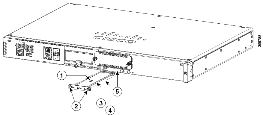
Insert the M.2 USB|NVMe module into the slot of the device (as shown in the figure). The slide should engage the internal card guides.

Step 3

Gently slide the M.2 USB|NVMe module all the way in until the faceplate is flush with the device.

Step 4

Screw down and tighten the two Philips head screws. Torque it to 4-6 in lbs.

Step 5

The device can now be powered on.

Figure 11. Install the M.2 USB|NVMe (Cisco 8200 Series Chassis)

1

M.2 USB|NVMe

2

Securing screws (torque 4-6 in-lbs)

3

M.2 module orientation with metal carrier on top, M.2 module underneath.

4

M.2 module underneath

5

Chassis cutout prevents M.2 installation in wrong orientation.