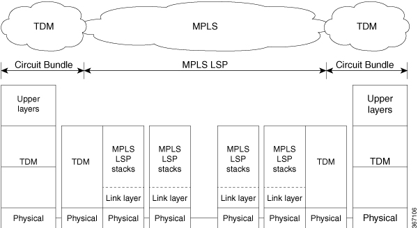
Structure-Agnostic TDM
over Packet (SAToP) encapsulates Time Division Multiplexing (TDM) bit-streams
as pseudowires over public switched networks. It disregards any structure that
may be imposed on streams, in particular the structure imposed by the standard
TDM framing.
The protocol used for emulation of these services does not depend on the method in which attachment circuits are delivered
to the Provider Edge (PE) chassis. For example, a T1 attachment circuit is treated the same way for all delivery methods,
including copper, multiplex in a T3 circuit, a virtual tributary of a SONET circuit, or unstructured Circuit Emulation Service
(CES).
In SAToP mode, the interface is considered as a continuous framed bit stream. The packetization of the stream is done according
to IETF RFC 4553. All signaling is carried out transparently as a part of a bit stream.

 Feedback