Cisco NCS 1001 Overview

This chapter provides an overview of Cisco NCS 1001.

Cisco NCS 1001 Overview

Cisco NCS 1001 (NCS1001-K9) is 1 RU chassis that addresses the growing bandwidth needs of data center DWDM applications. It provides a DWDM line system that is optimized for data center environments and is optimized for point-to-point applications at maximum capacity. NCS 1001 supports up to three optical modules. The modules can be amplifiers or protection switching modules.

NCS 1001 has the following components:

  • Removable control card

  • Four removable fans

  • Two removable 600W AC/DC or DC/DC power supply modules (PSU)

  • Three slots for optical modules. Two Optical Amplifier Modules ( NCS1K-EDFA) and a Protection Switching Module (NCS1K-PSM) can be inserted in these slots.

    The optical modules can be inserted in slots 1 to 3 as shown in the following figure. The optical modules can be inserted and removed from the slots while the system is operational. In amplified configuration, the Optical Amplifier module can be inserted in any slot. In (section) protected configuration, the protect Optical Amplifier module is inserted in slot 1, Protection Switching Module in slot 2, and working Optical Amplifier module in slot 3.


Caution


Each optical module must be inserted in a slot only when the module in the adjacent slot is completely inserted and seated or the adjacent slot is empty. If an optical module is inserted in a slot without seating the adjacent module, the ejector might interfere with the adjacent module.


Caution


The empty slots must be inserted with the filler optical modules or filler PSUs as appropriate to guarantee safety and system cooling compliance. See Cisco NCS 1001 Front View and Cisco NCS 1001 Rear View to identify the slots for optical modules and PSUs respectively.
Figure 1. Cisco NCS 1001 Front View

Cisco NCS 1001 Front View

1

Optical Module Slot 1

2

Optical Module Slot 2

3

Optical Module Slot 3

The slot numbers are also specified on the front panel label.

Figure 2. Cisco NCS 1001 Front View

Cisco NCS 1001 Front View

1

UDC (user data channel) for optical modules 1 and 2

2

Two USB 2.0 ports and one UDC for optical module 3

3

Two USB 2.0 ports and one 10/100/1000 LAN electrical management interface

4

10/100/1000 LAN management interface (optical)

5

Status LED (SFP link, Power supply, Fan, System, Beacon, OIR)

6

RS232 console port of the control card

7

OIR switch

Figure 3. Cisco NCS 1001 Rear View

Cisco NCS 1001 Rear View

1

Control card and SSD (Solid State Disk)

2

Fan 3

3

Fan 2

4

Fan 1

5

Fan 0

6

600W AC/DC or DC/DC redundant power supply module (PSU 1)

7

600W AC/DC or DC/DC redundant power supply module (PSU 0)

Both the power supply modules shall be AC/DC or DC/DC. Mixed configuration is not allowed.

Benefits

NCS 1001 provides the following benefits.

  • Up to 23dBm output power to allow for +3dBm per channel fiber launch power and maximum optical performance for high baud rate and higher order modulation format transponders.

  • Switchable gain pre-amplifier up to 34db.

  • Embedded Optical Channel Monitoring (OCM) module to monitor per channel power at all the input and output ports.

  • Integrated pluggable optics based OSC and OTDR support.

  • OSC supports user data channel transport as well as remote node management.

  • Supports 96 channels of C-Band in 1 RU.

  • Supports flex grid on OCM module.

Physical Characteristics

  • Width: 17.44” (442.9 mm)

  • Depth: 23.64” (600.5 mm)

  • Height: 1 RU

  • Weight without power supply unit: 8.2 kg

  • Weight with two power supply units: 10.5 kg

  • Weight of AC PSU: 1.162 kg

  • Weight of Fan: 78 gms

  • Weight of control card: 1.5 kg

For information about NCS 1001, see the data sheet.
Safety Labels

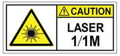
Cisco NCS 1000 Series chassis is classified as Hazard Level 1M as per IEC 60825-2 and Laser Class 1M as per IEC 60825-1, since it includes pluggable optical modules Class 1 or Class 1M.

The Class 1/1M Laser Product label is shown in the following figure:

Figure 4. Class 1/1M Laser Product Label
Class 1/1M Laser Product Label

This section explains the significance of the safety labels attached to the NCS 1001 chassis. The faceplates of the chassis are clearly labeled with warnings about the laser radiation levels.

You must understand all warning labels before working on the chassis.

Figure 5. Class 1M Laser Product Label


Safety Precaution for Module Installation and Removal

Ensure to observe the following safety precautions when you are working with the chassis modules.

Invisible laser radiations present. Statement 1016.

Invisible laser radiation may be emitted from disconnected fibers or connectors. Do not stare into beams or view directly with optical instruments. Statement 1051.

Figure 6. Class 1/1M Laser Product Label
Class 1/1M Laser Product Label

Safety Precaution for Laser Radiation

Cisco NCS 1000 Series chassis is classified as Hazard Level 1M as per IEC 60825-2 and Laser Class 1M as per IEC 60825-1, since it may include embedded or pluggable optical modules Class 1 or Class 1M.

Figure 7. Class 1M Laser Product Label


Optical Amplifier Module

Table 1. Feature History

Feature Name

Release Information

Feature Description

Amplifier Behaviour

Cisco IOS XR Release 7.3.1

Grid mode configuration for the optical amplifier has been extended to support 75GHz spaced channels.

You can optimize the optical spectrum and granularity using the gridless configuration. You can provision channels with arbitrary channel frequencies and channel widths. Up to 96 channels can be configured using the gridless configuration.

Commands modified:

  • hw-module

  • show controllers

The optical amplifier module (NCS1K-EDFA) has pre-amplifier and booster amplifier.

The optical amplifier module provides the following functionality.

  • Preamplifier (LINE-RX to COM-TX) - Single preamplifier variant, with switchable gain ranges, according to link loss:

    • Range # 1: 0 to 24 dB gain, Tilt control: 24 to 27 gain, with tilt uncontrolled

    • Range # 2: 20 to 34 dB gain, Tilt control: 34 to 37 dB gain, with tilt uncontrolled

    • 23dBm output power @ COM-TX port

  • Booster amplifier (COM-RX to LINE-TX) - True variable gain booster amplifier

    • Gain range: 1 to 20. 20 to 25 uncontrolled tilt.

    • 23dBm output power @ LINE-TX port

  • ADD/DROP OSC channel supports both 1510nm and 1610nm +/-10nm

  • OCM assesses channel presence and Gain regulation and per channel power monitoring.

Figure 8. EDFA Front View

EDFA Front View

1

XFP for OSC and additional OTDR feature

2

SFP for OSC (Optical Service Channel)

3

Status LED

4

Service Channel input and output port [OSC - RX, TX]

5

PRE and BST amplifier inputs and output ports

[L (LINE) - RX, TX]

[C (COM) - RX, TX]

[COM - CHECK]

The following table describes the mapping of controllers and optical ports for the optical amplifier module.

Controller

Optical Ports

Ots 0/slot/0/0

  • COM-RX (booster input)

  • COM-TX (preamplifier output)

Ots 0/slot/0/1

  • LINE-RX (preamplifier input)

  • LINE-TX (booster output)

Ots 0/slot/0/2

  • OSC-RX

  • OSC-TX

Ots 0/slot/0/3

COM-CHECK

COM-CHECK CONFIGURATION

The COM-CHECK configuration is described below.

  • Safety must be ensured to protect the fiber intra-node from the pre-amplifier to the Mux or Demux section for the total output power on COM-TX port upto 23 dB. This is required to compensate for an extremely lengthy span.

  • If the output power on COM-TX is less than or equal to 20 dB, the com-check port may not be used and can be turned off. Also no physical connection between the pre COM-CHECK and Demux monitor port is required.

  • Safety on pre is necessary in some cases such as large spans over high power requirements.

  • The COM-CHECK PD9 is the safety port.

  • The COM-RX like controller Ots 0/s/0/0 is not part of safety.

  • The safety restart process is similar to the booster case, with some difference in the APR Check phase.

Protection Switching Module

The protection switching module (NCS1K-PSM) provides the following functionality.

  • In TX section:

    • Splits input optical channels to both working and protection lines.

    • Forces the switch in the remote site by opening one of the two line paths (by putting the related VOA in AVS).

  • In RX section:

    • Selects the signals from working or protection line. Each line is monitored through a PD.

    • Balances the two line losses by changing the VOA attenuation value at the same time of the switch change of state.

Figure 9. PSM Front View

PSM Front View

1

Protected path input and output port [P - RX, TX]

2

Working path input and output port [W - RX, TX]

3

COM input and output port [COM - RX, TX]

4

Status LED

The following table describes the mapping of controllers and optical ports for the protection switching module.

Controller

Optical Ports

Ots 0/slot/0/0

COM-TX

Ots 0/slot/0/1

Working path input and output port [W - RX, TX]

Ots 0/slot/0/2

Protected path input and output port [P - RX, TX]

Optical Time Domain Reflectometer Module

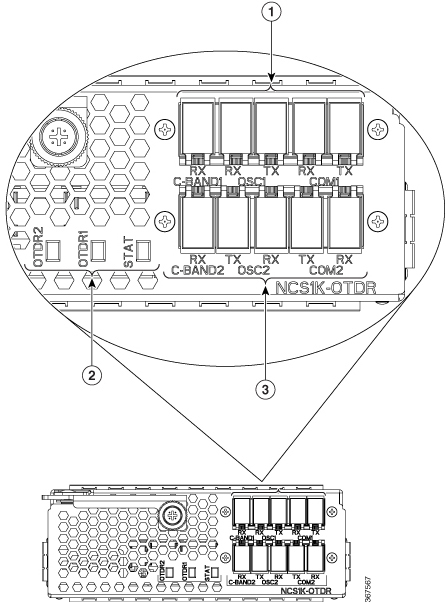
Optical Time Domain Reflectometer (OTDR) is a line card supported in NCS 1001. The line card contains 2x bidirectional OTDRs and 2x filter that combines C-band, OSC, and OTDR filters and splits OSC and OTDR. Each internal OTDR can perform measurements on both TX and RX fiber by using an internal optical switch. OTDR line card is connected to the OSC port on the optical amplifier. The OTDR line card can be inserted in any slot of NCS 1001.

Figure 10. OTDR Front View
OTDR Front View

1

OTDR1 interface

2

LED status

3

OTDR2 interface

For more information about the OTDR module, see the data sheet.

Cisco NCS 1000 32-Channel Even Mux/Demux Patch Panel

The Cisco NCS 1000 32-Channel Even Mux/Demux patch panel (PID: N1K-MD-32E-C) is a pair of passive Athermal Arrayed Waveguide Grating (AAWG) based modules.


Note


"Patch panel" refers to N1K-MD-32E-C Even Mux/Demux patch panel.


The patch panel has 32 channels and works as an add/drop unit for its 32 channels at 140 GBd. Each even patch panel allows the multiplexing and demultiplexing of 32 channels with 150-GHz spacing. The patch panel provides a wide spectrum of optical wavelengths support.

The N1K-MD-32E-C patch panel operates in C-band. This even patch panel is fully passive.

Figure 11. N1K-MD-32E-C Patch Panel Front View

Port Label Descriptions

The even patch panel has 34-port LC-duplex connectors.

Table 2. Even Mux/Demux Patch Panel Port Interfaces

Port

Connector Type

Connector Label

Operating Frequency Range [THz (nm)]

Note

COM-RX

COM-TX

LC

COM

191.3–196.1 (1528.77–1567.13)

TX

RX

MON-RX

MON-TX

LC

MON

196.175–191.15 (1528.2–1568.4)

Both are output ports. Replica of COM-RX/TX signals ~20dB attenuated.

TX

RX

CH-i TX/RX

[i=0–31]

LC

<frequency>

For more information on EVEN channels, see Channel Wavelength Allocation

TX

RX

INV

USB Type A receptacle connector

INV

USB inventory port.

Channel Wavelength Allocation

The following table describes the C-band channel wavelength plan for the patch panel.

Table 3. C-Band Channel Wavelength Plan

Channel Label

N1K-MD-32E-C

Frequency (THz)

Wavelength (nm)

0

196.025

1529.36

1

195.875

1530.53

2

195.725

1531.70

3

195.575

1532.88

4

195.425

1534.05

5

195.275

1535.23

6

195.125

1536.41

7

194.975

1537.59

8

194.825

1538.78

9

194.675

1539.96

10

194.525

1541.15

11

194.375

1542.34

12

194.225

1543.53

13

194.075

1544.72

14

193.925

1545.92

15

193.775

1547.12

16

193.625

1548.31

17

193.475

1549.52

18

193.325

1550.72

19

193.175

1551.92

20

193.025

1553.13

21

192.875

1554.34

22

192.725

1555.55

23

192.575

1556.76

24

192.425

1557.97

25

192.275

1559.19

26

192.125

1560.40

27

191.975

1561.62

28

191.825

1562.84

29

191.675

1564.07

30

191.525

1565.29

31

191.375

1566.52

USB Passive Inventory

Table 4. Feature History

Feature Name

Release

Description

Inventory Support

Cisco IOS XR Release 7.3.1

A new passive device with PID NCS1K-MD-64-C (NCS 1000 64 channels Odd Multiplexer or Demultiplexer Patch Panel-C-band) is supported.

There are passive units that are part of NCS 1001 hardware configuration. It is possible to have information about these passive units as soon as they are connected with a proper USB cable through one of the four available USB ports on the controller card of the box itself.

In this case their basic parameters are displayed in the output of “show inventory” command by XR or admin session.

The following passive modules are supported in NCS 1001:

Table 5. Passive modules supported in NCS 1001

PID

Description

15216-MD-48-ODDE

ONS Multiplexer/Demultiplexer Patch Panel Even Extended

15216-MD-48-EVENE

ONS Multiplexer/Demultiplexer Patch Panel Odd Extended

15216-MD-48-CME

ONS Coupler and Splitter

15216-FLD-OSC

OSC Combiner and Splitter

NCS1K-MD-64-C

NCS 1000 64 channels Odd Multiplexer/Demultiplexer Patch Panel-C-band

N1K-MD-32E-C

NCS 1000 32 channels Even Multiplexer/Demultiplexer Patch Panel, No-loopback - 150GHz - C-band


Remember


N1K-MD-32E-C and NCS1K-MD-32E-C are 32-channel even multiplexer/demultiplexer patch panels. The N1K-MD-32E-C does not have a loopback function and is compatible only with the NCS 1001. The NCS1K-MD-32E-C supports a loopback function and is compatible only with the NCS 1010.


When the supported passive module is connected to the front panel port of NCS 1001, the module is discovered and the inventory data is read from the USB device. The user can view the details of passive module such as PID, Description, Serial Number, and Version ID using the show inventory command. Only one passive unit information can be retrieved in the inventory of the box , if it is connected to the box itself through a cable to one of the available four USB ports.

The same parameter plus others are also obtainable in the response to SNMP get on “entPhysicalEntity” objects

Example

RP/0/RP0/CPU0:MYS-127#show inventory                              
Wed May 23 08:24:07.350 CEST…………

NAME: "0/RP0-USB0", DESCR: "ONS Mux/Demux Patch Panel Even Extended"
PID: 15216-MD-48-EVENE , VID: V01 , SN: NSZ19510021

NAME: "0/RP0-USB1", DESCR: "OSC Combiner-Splitter Module"
PID: 15216-FLD-OSC=    , VID: V00 , SN: OPL17190305

NAME: "0/RP0-USB2", DESCR: "ONS Mux/Demux Patch Panel Odd Extended"
PID: 15216-MD-48-ODDE  , VID: V01 , SN: NSZ19510003

NAME: "0/RP0-USB3", DESCR: "ONS Coupler and Splitter Pluggable"
PID: 15216-MD-48-CME   , VID: V01 , SN: NSZ20159002

Product IDs

Table 6. Feature History

Feature Name

Release Information

Feature Description

ONS-SE-155-1510 Support

Cisco IOS XR Release 7.3.2

A new SFP pluggable optics module with PID ONS-SE-155-1510 SFP is supported.

The following table describes the product IDs of the components.

Product ID

Description

NCS1001-K9=

Network Convergence System 1001 line system 3 slots

NCS1K-CNTLR2=

Network Convergence System 1001 Control card

NCS1K-EDFA=

Network Convergence System 1001 amplifier module

NCS1K-PSM=

Network Convergence System 1001 protection module

NCS1K-OTDR=

Network Convergence System 1001 OTDR module

NCS1K-2KW-AC2=

Network Convergence System 1001 AC power supply unit - 2KW normal operating temperature, 600W short term high temperature

NCS1K-2KW-DC=

Network Convergence System 1001 DC power supply unit - 2KW normal operating temperature, 600W short term high temperature

NCS1K1-FAN=

Network Convergence System 1001 line system Fan

NCS1K-SSD=

SSD

ONS-SC-Z3-1510=

SFP OC-48/STM-16/GE, CWDM, 1510 nm

ONS-SE-155-1510

SFP OC-3/STM-1, CWDM, 1510 nm EXT; SFP Pluggable Optics Module

CWDM-SFP-1510

CWDM 1510-nm SFP; Gigabit Ethernet 1 and 2 Gb Fibre Channel

CWDM-SFP-1610

CWDM 1610-nm SFP; Gigabit Ethernet 1 and 2 Gb Fibre Channel

ONS-SC-Z3-1610=

SFP OC-48/STM-16/GE, CWDM, 1610 nm

ONS-SI-GE-LX=

SFP 1000BASE-LX Gigabit Ethernet, 1310 nm, SM, I-TEMP

ONS-SI-GE-SX=

SFP 1000BASE-SX Gigabit Ethernet, 850 nm, MM, I-TEMP

ONS-SI-GE-ZX=

SFP 1000BASE-ZX Gigabit Ethernet, 1550 nm, SM, I-Temp

ONS-SC-Z3-1510=

SFP OC-48/STM-16/GE, CWDM, 1510 nm

ONS-SC-Z3-1610=

SFP OC-48/STM-16/GE, CWDM, 1610 nm

LEDs in Cisco NCS 1001

LED

State

Description

SYS

Green

The unit is operating correctly.

Yellow

The unit has one or more errors detected.

Off

Power is not applied to the unit.

BCN

Blue

The unit needs attention.

Off

The unit does not need attention.

SFP

Green

The SFP link is up.

Yellow

The link is down, active alarms are present on this port, or a hardware failure has occurred.

Off

The port is not provisioned by the software, the optics module is missing, or the port does not have power.

PSU and FAN

Green

The unit is operating correctly.

Red

The unit has one or more errors detected.

OIR

Off

The control card is not present or not properly inserted.

Amber Blinking

The software is not operating correctly as the control card may not be correctly inserted.

Amber Solid

The control card, BIOS, and software are functional.

32-Channel Even Mux/Demux Panel LEDs

The behaviour of the 32-channel even mux/demux pannel LEDs are similar to the 32-channel mux/demux patch panel LEDs. For information, see Mux/Demux Patch Panel LEDs.