L2VPN and Ethernet Services Configuration Guide for Cisco NCS 560 Series Routers, IOS XR Release 24.1.x, 24.2.x, 24.3.x, 24.4.x
Bias-Free Language
The documentation set for this product strives to use bias-free language. For the purposes of this documentation set, bias-free is defined as language that does not imply discrimination based on age, disability, gender, racial identity, ethnic identity, sexual orientation, socioeconomic status, and intersectionality. Exceptions may be present in the documentation due to language that is hardcoded in the user interfaces of the product software, language used based on RFP documentation, or language that is used by a referenced third-party product. Learn more about how Cisco is using Inclusive Language.
This chapter describes how to configure Layer 2 Ethernet VPN (EVPN) features on the router.
EVPN
Overview
Ethernet VPN (EVPN) is a solution that provides Ethernet multipoint services over MPLS networks. EVPN operates in contrast
to the existing Virtual Private LAN Service (VPLS) by enabling control-plane based MAC learning in the core. In EVPN, PEs
participating in the EVPN instances learn customer MAC routes in control-plane using MP-BGP protocol. Control-plane MAC learning
brings a number of benefits that allow EVPN to address the VPLS shortcomings, including support for multihoming with per-flow
load balancing.
EVPN provides the solution for network operators for the following emerging needs in their network:
Data center interconnect operation (DCI)
Cloud and services virtualization
Remove protocols and network simplification
Integration of L2 and L3 services over the same VPN
Flexible service and workload placement
Multi-tenancy with L2 and L3 VPN
Optimal forwarding and workload mobility
Fast convergence
Efficient bandwidth utilization
EVPN
Benefits
The EVPN provides
the following benefits:
Integrated Services: Integrated L2 and L3 VPN services, L3VPN-like principles and operational experience for scalability and
control, all-active multihoming and PE load-balancing using ECMP, and enables load balancing of traffic to and from CEs that
are multihomed to multiple PEs.
Network Efficiency: Eliminates flood and learn mechanism, fast-reroute, resiliency, and faster reconvergence when the link
to dual-homed server fails, optimized Broadcast, Unknown-unicast, Multicast (BUM) traffic delivery.
Service
Flexibility: MPLS data plane encapsulation, support existing and new services
types (E-LAN, E-Line), peer PE auto-discovery, and redundancy group
auto-sensing.
EVPN Modes
The following EVPN modes are supported:
Single-homing - Enables you to connect a customer edge (CE) device to one provider edge (PE) device.
Multihoming - Enables you to connect a customer edge (CE) device to more than one provider edge (PE) device. Multihoming ensures
redundant connectivity. The redundant PE device ensures that there is no traffic disruption when there is a network failure.
Following are the types of multihoming:
All-Active - In all-active mode all the PEs attached to the particular Ethernet-Segment is allowed to forward traffic to and
from that Ethernet Segment.
EVPN Restrictions
When paths of different technologies are resolved over ECMP, it results in heterogeneous ECMP, leading to severe network traffic issues. Don’t use ECMP for any combination of the following technologies:
LDP.
BGP-LU, including services over BGP-LU loopback peering or recursive services at Level-3
VPNv4.
6PE and 6VPE.
EVPN.
Recursive static routing.
EVPN
Concepts
To implement EVPN
features, you need to understand the following concepts:
Ethernet Segment
(ES): An Ethernet segment is a set of Ethernet links that connects a multihomed
device. If a multi-homed device or network is connected to two or more PEs
through a set of Ethernet links, then that set of links is referred to as an
Ethernet segment. The Ethernet segment route is also referred to as Route Type
4. This route is used for designated forwarder (DF) election for BUM traffic.
Ethernet Segment
Identifier (ESI): Ethernet segments are assigned a unique non-zero identifier,
which is called an Ethernet Segment Identifier (ESI). ESI represents each
Ethernet segment uniquely across the network.
EVI: The EVPN
instance (EVI) is represented by the virtual network identifier (VNI). An EVI
represents a VPN on a PE router. It serves the same role of an IP VPN Routing
and Forwarding (VRF), and EVIs are assigned import/export Route Targets (RTs).
Depending on the service multiplexing behaviors at the User to Network
Interface (UNI), all traffic on a port (all-to-one bundling), or traffic on a
VLAN (one-to-one mapping), or traffic on a list/range of VLANs (selective
bundling) can be mapped to a Bridge Domain (BD). This BD is then associated to
an EVI for forwarding towards the MPLS core.
EAD/ES: Ethernet
Auto Discovery Route per ES is also referred to as Route Type 1. This route is
used to converge the traffic faster during access failure scenarios. This route
has Ethernet Tag of 0xFFFFFFFF.
EAD/EVI: Ethernet Auto Discovery Route per EVI is also referred to as Route Type 1. This route is used for aliasing and load
balancing when the traffic only hashes to one of the switches. This route cannot have Ethernet tag value of 0xFFFFFFFF to
differentiate it from the EAD/ES route.
Aliasing: It is
used for load balancing the traffic to all the connected switches for a given
Ethernet segment using the Route Type 1 EAD/EVI route. This is done
irrespective of the switch where the hosts are actually learned.
Mass Withdrawal:
It is used for fast convergence during the access failure scenarios using the
Route Type 1 EAD/ES route.
DF Election: It is
used to prevent forwarding of the loops. Only a single router is allowed to
decapsulate and forward the traffic for a given Ethernet Segment.
EVPN
Operation
At startup, PEs
exchange EVPN routes in order to advertise the following:
VPN
membership: The PE discovers all remote PE members of a given EVI. In the
case of a multicast ingress replication model, this information is used to
build the PEs flood list associated with an EVI. BUM labels and unicast labels
are exchanged when MAC addresses are learned.
Ethernet segment
reachability: In multihoming scenarios, the PE auto-discovers remote PE and
their corresponding redundancy mode (all-active or single-active). In case of
segment failures, PEs withdraw the routes used at this stage in order to
trigger fast convergence by signaling a MAC mass withdrawal on remote PEs.
Redundancy Group
membership: PEs connected to the same Ethernet segment (multihoming)
automatically discover each other and elect a Designated Forwarder (DF) that is
responsible for forwarding Broadcast, Unknown unicast and Multicast (BUM)
traffic for a given EVI.
Figure 1. EVPN
Operation
EVPN can operate in
single-homing or dual-homing mode. Consider single-homing scenario, when EVPN
is enabled on PE, Route Type 3 is advertised where each PE discovers all other
member PEs for a given EVPN instance. When an unknown unicast (or BUM) MAC is
received on the PE, it is advertised as EVPN Route Type 2 to other PEs. MAC
routes are advertised to the other PEs using EVPN Route Type 2. In multihoming
scenarios, Route Types 1, 3, and 4 are advertised to discover other PEs and
their redundancy modes (single-active or all-active). Use of Route Type 1 is to
auto-discover other PE which hosts the same CE. The other use of this route
type is to fast route unicast traffic away from a broken link between CE and
PE. Route Type 4 is used for electing designated forwarder. For instance,
consider the topology when customer traffic arrives at the PE, EVPN MAC
advertisement routes distribute reachability information over the core for each
customer MAC address learned on local Ethernet segments. Each EVPN MAC route
announces the customer MAC address and the Ethernet segment associated with the
port where the MAC was learned from and its associated MPLS label. This EVPN
MPLS label is used later by remote PEs when sending traffic destined to the
advertised MAC address.
Behavior Change due to ESI Label Assignment
To adhere to RFC 7432 recommendations, the encoding or decoding of MPLS label is modified for extended community. Earlier,
the lower 20 bits of extended community were used to encode the split-horizon group (SHG) label. Now, the SHG label encoding
uses from higher 20 bits of extended community.
According to this change, routers in same ethernet-segment running old and new software release versions decodes extended
community differently. This change causes inconsistent SHG labels on peering EVPN PE routers. Almost always, the router drops
BUM packets with incorrect SHG label. However, in certain conditions, it may cause remote PE to accept such packets and forward
to CE potentially causing a loop. One such instance is when label incorrectly read as NULL.
To overcome this problem, Cisco recommends you to:
Minimize the time both PEs are running different software release versions.
Before upgrading to a new release, isolate the upgraded node and shutdown the corresponding AC bundle.
After upgrading both the PEs to the same release, you can bring both into service.
Similar recommendations are applicable to peering PEs with different vendors with SHG label assignment that does not adhere
to RFC 7432.
EVPN Route
Types
The EVPN network
layer reachability information (NLRI) provides different route types.
Table 1. EVPN Route
Types
Route Type
Name
Usage
1
Ethernet
Auto-Discovery (AD) Route
Few routes
are sent per ES, carries the list of EVIs that belong to ES
The Ethernet
Auto-Discovery (AD) routes are advertised on per EVI and per ESI basis. These
routes are sent per ES. They carry the list of EVIs that belong to the ES. The
ESI field is set to zero when a CE is single-homed. This route type is used for
mass withdrawal of MAC addresses and aliasing for load balancing.
Route Type 2:
MAC/IP Advertisement Route
These routes are
per-VLAN routes, so only PEs that are part of a VNI require these routes. The
host's IP and MAC addresses are advertised to the peers within NRLI. The
control plane learning of MAC addresses reduces unknown unicast flooding.
Route Type 3:
Inclusive Multicast Ethernet Tag Route
This route
establishes the connection for broadcast, unknown unicast, and multicast (BUM)
traffic from a source PE to a remote PE. This route is advertised on per VLAN
and per ESI basis.
Route Type 4:
Ethernet Segment Route
Ethernet segment
routes enable to connect a CE device to two or PE devices. ES route enables the
discovery of connected PE devices that are connected to the same Ethernet
segment.
Route Type 5: IP
Prefix Route
The IP prefixes are
advertised independently of the MAC-advertised routes. With EVPN IRB, host
route /32 is advertised using RT-2 and subnet /24 is advertised using RT-5.
Note
With EVPN IRB,
host route /32 are advertised using RT-2 and subnet /24 are advertised using
RT-5.
EVPN Timers
The following table shows various EVPN timers:
Configure EVPN L2
Bridging Service
Perform the following steps to configure EVPN L2 bridging service.
Note
Always ensure to change the label mode from per-prefix to per-VRF label mode. Since L2FIB and VPNv4 route (labels) shares
the same resource, BVI ping fails when you exhaust the resources.
Note
Traffic to directly connected neighbor on EVPN or VPLS bridge won't work in the following
scenarios:
If neighbor doesn't advertise MPLS explicit null.
If imposition node has a mix of implicit-null and labeled paths in ECMP or LFA
deployment.
Note
A device can contain up to 128K MAC address entries. A bridge domain on a device can contain up to 64K MAC address entries.
Note
Flooding disable isn’t supported on EVPN bridge domains.
/* Configure address family session in BGP */
RP/0/RSP0/CPU0:router# configure
RP/0/RSP0/CPU0:router#(config)# router bgp 200
RP/0/RSP0/CPU0:router#(config-bgp)# bgp router-id 209.165.200.227
RP/0/RSP0/CPU0:router#(config-bgp)# address-family l2vpn evpn
RP/0/RSP0/CPU0:router#(config-bgp)# neighbor 10.10.10.10
RP/0/RSP0/CPU0:router#(config-bgp-nbr)# remote-as 200
RP/0/RSP0/CPU0:router#(config-bgp-nbr)# description MPLSFACING-PEER
RP/0/RSP0/CPU0:router#(config-bgp-nbr)# update-source Loopback 0
RP/0/RSP0/CPU0:router#(config-bgp-nbr)# address-family l2vpn evpn

/* Configure EVI and define the corresponding BGP route targets */
Note
EVI route target used for multicast EVPN supports only extcomm type sub-type 0xA for EVI
route target, the two-octet Autonomous System (AS) specific Extended Community. This means
that when using a 4-byte AS number for BGP, you must additionally configure BGP import and
export route targets under the EVPN configuration.
In single-active multihoming mode, only a single edge (PE) Router among a group of PE
Routers attached to a host is allowed to send and recieve traffic on a given VLAN.
The single-active mode offers redundant connectivity for a VLAN on a single link at a time with failover to the second link
in case the active link fails. The single-active mode directs the traffic to a single uplink. This mode is useful for network
scenarios where policing, metering, and billing are required.
In Single-Active mode, Cisco IOS XR sends a topology change notification on the Ethernet segment links when a service carving
update occurs, so that CEs flush their MAC tables and redirect traffic to the new DF-Elected PE.
Starting from Cisco IOS XR Release 7.11.2, the MAC flush message can be disabled for an Ethernet segment if it causes undesired
behaviour at the CE, like triggering BPDU guard. Use the mac-flush-message disable command to disable the MAC flush messages.
Topology
Let's understand how the single-active mode works with this sample topology.
In this topology,
The CE Router is multihomed to PE1 and PE2. Only one active uplink is allowed
to send and receive traffic at any given time.
In this mode, each link towards PE is in a unique ethernet bundle interface. In this example, BE1 is the ethernet bundle interface
connecting CE1 and PE1. BE2 is the ethernet bundle interface connecting CE1 and PE2.
As both the links are in a separate ethernet bundle interface, CE1 floods traffic at first to both the PE devices, but only
the PE that is the Designated Forwarder (DF) forwards the traffic.
In this mode, the uplinks to PE1 and PE2 are individual links and by default, the host chooses the DF uplink for forwarding
for a given VLAN.
Configure EVPN Single-Active Multi-Homing
Perform the following tasks to configure EVPN single-active multi-homing:
Configure Ethernet bundles on CE1 for multi-homing.
Configure EVPN based single-active multi-homing.
Note
Sub-interface shutdown is not supported in Single-Active load-balancing mode
Configure Ethernet bundles on CE1 for Multihoming:
Router#configure
Router(config)#interface Bundle-Ether1
Router(config-if)#no shutdown
Router(config-if)#exit
Router(config)#interface Bundle-Ether2
Router(config-if)# no shutdown
Router(config)#exit
Router(config)#interface HundredGigE0/0/0/0
Router(config-if)#bundle id 1 mode active
Router(config-if)#no shutdown
Router(config-if)#exit
Router(config)#interface HundredGigE0/0/0/1
Router(config-if)#bundle id 2 mode active
Router(config-if)#no shutdown
Router(config-if)#exit
Router(config)#interface HundredGigE0/0/0/2
Router(config-if)#exit
Router(config)#interface HundredGigE0/0/0/3
Router(config-if)#no shutdown
Router(config-if)#commit
Router(config-if)#exit
Router(config)#interface Bundle-Ether1.10 l2transport
Router(config-subif)#encapsulation dot1q 10
Router(config-subif)#rewrite ingress tag pop 1 symmetric
Router(config-subif)#commit
Router(config-subif)#exit
Router(config)#interface Bundle-Ether2.10 l2transport
Router(config-subif)#encapsulation dot1q 10
Router(config-subif)#rewrite ingress tag pop 1 symmetric
Router(config-subif)#commit
Router(config-subif)#root
Router(config)#interface BVI10
Router(config-if)#ipv4 address 10.0.0.10 255.255.255.0
Router(config-if)exit
Router(config)#interface BVI10
Router(config-if)#ipv4 address 10.0.0.10 255.255.255.0
Router(config-if)#exit
Router(config)#l2vpn
Router(config-l2vpn)#bridge group bg1
Router(config-l2vpn-bg)#bridge-domain bd-10
Router(config-l2vpn-bg-bd)#interface Bundle-Ether1.10
Router(config-l2vpn-bg-bd-ac)#exit
Router(config-l2vpn-bg-bd)#interface Bundle-Ether2.10
Router(config-l2vpn-bg-bd-ac)#exit
Router(config-l2vpn-bg-bd)#routed interface BVI10
Router(config-l2vpn-bg-bd-bvi)#commit
Configure EVPN based single-active multi-homing on PE Routers.
This section shows the single-active running configuration.
/* CE1 Configuration */
interface Bundle-Ether1
!
interface Bundle-Ether1.10 l2transport
 encapsulation dot1q 10
 rewrite ingress tag pop 1 symmetric
!
interface Bundle-Ether2
!
interface Bundle-Ether2.10 l2transport
 encapsulation dot1q 10
 rewrite ingress tag pop 1 symmetric
!
interface Loopback0
 ipv4 address 200.0.0.7 255.255.255.255
!
interface MgmtEth0/RSP0/CPU0/0
 ipv4 address dhcp
!
interface BVI10
 description "Host-1 IP"
 ipv4 address 10.0.0.10 255.255.255.0
!
interface HundredGigE0/0/0/0
 bundle id 1 mode active
!
interface HundredGigE0/0/0/1
 description "Link to Leaf-2"
 bundle id 2 mode active
!
l2vpn
 bridge group bg1
  bridge-domain bd-10
   interface Bundle-Ether1.10
   !
   interface Bundle-Ether2.10
   !
   routed interface BVI10
   !
  !
/* PE1 Configuration */
evpn
 evi 100
  advertise-mac
  !
 !
 interface Bundle-Ether1
  ethernet-segment
  identifier type 0 36.37.00.00.00.00.00.11.00
   load-balancing-mode single-active
  !
 !
!
l2vpn
 bridge group 100
  bridge-domain 100
   interface Bundle-Ether1.10
   !
   evi 100
   !
  !
 !
!
commit
root
exit
/* PE2 Configuration */
evpn
 evi 100
  advertise-mac
  !
 !
 interface Bundle-Ether2
  ethernet-segment
   identifier type 0 36.37.00.00.00.00.00.11.00
   load-balancing-mode single-active
  !
 !
!
l2vpn
 bridge group 100
  bridge-domain 100
   interface Bundle-Ether2.10
   !
   evi 100
   !
  !
 !
!
Verification
The following output shows that the EVPN single-active mode is enabled:
Router#show evpn ethernet-segment detail

Legend:
  B   - No Forwarders EVPN-enabled,
  C   - Backbone Source MAC missing (PBB-EVPN),
  RT  - ES-Import Route Target missing,
  E   - ESI missing,
  H   - Interface handle missing,
  I   - Name (Interface or Virtual Access) missing,
  M   - Interface in Down state,
  O   - BGP End of Download missing,
  P   - Interface already Access Protected,
  Pf  - Interface forced single-homed,
  R   - BGP RID not received,
  S   - Interface in redundancy standby state,
  X   - ESI-extracted MAC Conflict
  SHG - No local split-horizon-group label allocated

Ethernet Segment Id      Interface                          Nexthops
------------------------ ---------------------------------- --------------------
0036.3700.0000.0000.1100 BE1                                10.1.1.1
                                                            10.2.2.2
  ES to BGP Gates   : Ready
  ES to L2FIB Gates : Ready
  Main port         :
     Interface name : Bundle-Ether1
     Interface MAC  : 0008.3302.3208
     IfHandle       : 0x02000160
     State          : Up
     Redundancy     : Not Defined
  ESI type          : 0
     Value          : 36.3700.0000.0000.1100
  ES Import RT      : 3637.0000.0000 (from ESI)
  Source MAC        : 0000.0000.0000 (N/A)
  Topology          :
     Operational    : MH, Single-active
     Configured     : Single-active (AApS)
  Service Carving   : Auto-selection
     Multicast      : Disabled
  Convergence       :
     Mobility-Flush : Count 0, Skip 0, Last n/a
  Peering Details   : 2 Nexthops
     10.1.1.1 [MOD:P:00]
     10.2.2.2 [MOD:P:00]
  Service Carving Results:
     Forwarders     : 1
     Elected        : 1
     Not Elected    : 0
  EVPN-VPWS Service Carving Results:
     Primary        : 0
     Backup         : 0
     Non-DF         : 0
  MAC Flushing mode : STP-TCN
  Peering timer     : 3 sec [not running]
  Recovery timer    : 30 sec [not running]
  Carving timer     : 0 sec [not running]
  Local SHG label   : 24007
  Remote SHG labels : 1
              24007 : nexthop 10.2.2.2
  Access signal mode: Bundle OOS (Default)
The following output shows that Bundle-Ether1 is up:
Router:PE1#show bundle bundle-ether 1

Bundle-Ether1
  Status:                                    Up
  Local links <active/standby/configured>:   1 / 0 / 1
  Local bandwidth <effective/available>:     100000000 (100000000) kbps
  MAC address (source):                      0008.3532.0137 (Chassis pool)
  Inter-chassis link:                        No
  Minimum active links / bandwidth:          1 / 1 kbps
  Maximum active links:                      64
  Wait while timer:                          2000 ms
  Load balancing:
    Link order signaling:                    Not configured
    Hash type:                               Default
    Locality threshold:                      None
  LACP:                                      Operational
    Flap suppression timer:                  Off
    Cisco extensions:                        Disabled
    Non-revertive:                           Disabled
  mLACP:                                     Not configured
  IPv4 BFD:                                  Not configured
  IPv6 BFD:                                  Not configured

  Port                  Device           State        Port ID         B/W, kbps
  --------------------  ---------------  -----------  --------------  ----------
  Hu0/0/0/0             Local            Active       0x8000, 0x0001   100000000
      Link is Active
Disable MAC Flush Messages for EVPN Single-Active Multi-Homing
To disable the MAC flush messages on an Ethernet segment, use the mac-flush-message disable while configuring EVPN single-active multi-homing on PE Routers.
evpn
 evi 100
  advertise-mac
  !
 !
 interface Bundle-Ether1
  ethernet-segment
   identifier type 0 36.37.00.00.00.00.00.11.00
   load-balancing-mode single-active
  !
  mac-flush-message disable
  !
 !
!
l2vpn
 bridge group 100
  bridge-domain 100
   interface Bundle-Ether1.10
   !
   evi 100
   !
  !
 !
!
Verification
The following output shows MAC flush message being disabled:
Router#show evpn ethernet-segment detail

Legend:
  B   - No Forwarders EVPN-enabled,
  C   - Backbone Source MAC missing (PBB-EVPN),
  RT  - ES-Import Route Target missing,
  E   - ESI missing,
  H   - Interface handle missing,
  I   - Name (Interface or Virtual Access) missing,
  M   - Interface in Down state,
  O   - BGP End of Download missing,
  P   - Interface already Access Protected,
  Pf  - Interface forced single-homed,
  R   - BGP RID not received,
  S   - Interface in redundancy standby state,
  X   - ESI-extracted MAC Conflict
  SHG - No local split-horizon-group label allocated

Ethernet Segment Id      Interface                          Nexthops
------------------------ ---------------------------------- --------------------
0036.3700.0000.0000.1100 BE1                                10.1.1.1
                                                            10.2.2.2
  ES to BGP Gates   : Ready
  ES to L2FIB Gates : Ready
  Main port         :
     Interface name : Bundle-Ether1
     Interface MAC  : 0008.3302.3208
     IfHandle       : 0x02000160
     State          : Up
     Redundancy     : Not Defined
  ESI type          : 0
     Value          : 36.3700.0000.0000.1100
  ES Import RT      : 3637.0000.0000 (from ESI)
  Source MAC        : 0000.0000.0000 (N/A)
  Topology          :
    Operational    : MH, Single-active
     Configured     : Single-active (AApS)
  Service Carving   : Auto-selection
     Multicast      : Disabled
  Convergence       :
     Mobility-Flush : Count 0, Skip 0, Last n/a
  Peering Details   : 2 Nexthops
     10.1.1.1 [MOD:P:00]
     10.2.2.2 [MOD:P:00]
 Service Carving Results:
     Forwarders     : 1
     Elected        : 1
     Not Elected    : 0
  EVPN-VPWS Service Carving Results:
     Primary        : 0
     Backup         : 0
     Non-DF         : 0
  MAC Flush msg     : Disabled
  Peering timer     : 3 sec [not running]
  Recovery timer    : 30 sec [not running]
  Carving timer     : 0 sec [not running]
  Local SHG label   : 24007
  Remote SHG labels : 1
              24007 : nexthop 10.2.2.2
  Access signal mode: Bundle OOS (Default)
EVPN Software MAC
Learning
The MAC addresses
learned on one device needs to be learned or distributed on the other devices
in a VLAN. EVPN Software MAC Learning feature enables the distribution of the
MAC addresses learned on one device to the other devices connected to a
network. The MAC addresses are learnt from the remote devices using BGP.
Note
A device can contain up to 128K MAC address entries. A bridge domain on a device can contain up to 64K MAC address entries.
Figure 2. EVPN Software
MAC Learning
The above figure
illustrates the process of software MAC learning. The following are the steps
involved in the process:
Traffic comes in
on one port in the bridge domain.
The source MAC
address (AA) is learnt on the PE and is stored as a dynamic MAC entry.
The MAC address
(AA) is converted into a type-2 BGP route and is sent over BGP to all the
remote PEs in the same EVI.
The MAC address
(AA) is updated on the PE as a remote MAC address.
Configure EVPN
Software MAC Learning
The following section
describes how you can configure EVPN Software MAC Learning:
Note
On EVPN bridge domain, the router does not support control word and does not enable control word by default.
From Release 7.4.1 Control word is enabled by default. If the control-word-disable command is not configured, ensure to configure it under EVPN or EVI configuration mode before an upgrade to avoid inconsistent
behaviour with routers running before Release 7.4.2.
If you want to enable control-word command for EVPN Bridging feature, then you must configure it only when both the endpoints run Release 7.4.1 or later.
If you want to disable control word command, use control-word-disable before Release 7.8.1, it needed a router to reload to take effect.
Note
The router does not support flow-aware transport (FAT) pseudowire.
The following are the
modes in which EVPN Software MAC Learning is supported:
Single Home Device
(SHD) or Single Home Network (SHN)
Dual Home Device
(DHD)—All Active Load Balancing
Single Home Device
or Single Home Network Mode
The following section
describes how you can configure EVPN Software MAC Learning feature in single
home device or single home network (SHD/SHN) mode:
Figure 3. Single Home
Device or Single Home Network Mode
In the above figure,
the PE (PE1) is attached to Ethernet Segment using bundle or physical
interfaces. Null Ethernet Segment Identifier (ESI) is used for SHD/SHN.
Configure EVPN in
Single Home Device or Single Home Network Mode
This section describes
how you can configure EVPN Software MAC Learning feature in single home device
or single home network mode.
/* Configure bridge domain. */

RP/0/RSP0/CPU0:router(config)# l2vpn
RP/0/RSP0/CPU0:router(config-l2vpn)# bridge group EVPN_ALL_ACTIVE
RP/0/RSP0/CPU0:router(config-l2vpn-bg)# bridge-domain EVPN_2001
RP/0/RSP0/CPU0:router(config-l2vpn-bg-bd)# interface Bundle-Ether1.2001
RP/0/RSP0/CPU0:router(config-l2vpn-bg-bd)# evi 2001
/* Configure advertisement of MAC routes. */

RP/0/RSP0/CPU0:router(config)# evpn
RP/0/RSP0/CPU0:router(config-evpn)# evi 2001
RP/0/RSP0/CPU0:router(config-evpn-evi)# advertise-mac
RP/0/RSP0/CPU0:router# show evpn ethernet-segment interface Te0/4/0/10 detail

Ethernet Segment Id    Interface   Nexthops
--------------------   ----------  ----------
N/A     													  Te0/4/0/10  20.20.20.20
……………
 Topology :
 Operational : SH
 Configured : Single-active (AApS) (default)
Dual Home
Device—All-Active Load Balancing Mode
The following section
describes how you can configure EVPN Software MAC Learning feature in dual home
device (DHD) in all-active load balancing mode:
Figure 4. Dual Home Device
—All-Active Load Balancing Mode
All-active
load-balancing is known as Active/Active per Flow (AApF). In the above figure,
identical Ethernet Segment Identifier is used on both EVPN PEs. PEs are
attached to Ethernet Segment using bundle interfaces. In the CE, single bundles
are configured towards two EVPN PEs. In this mode, the MAC address that is
learnt is stored on both PE1 and PE2. Both PE1 and PE2 can forward the traffic
within the same EVI.
Configure EVPN
Software MAC Learning in Dual Home Device—All-Active Mode
This section describes
how you can configure EVPN Software MAC Learning feature in dual home
device—all-active mode:
/* Configure bridge domain. */

RP/0/RSP0/CPU0:router(config)# l2vpn
RP/0/RSP0/CPU0:router(config-l2vpn)# bridge group EVPN_ALL_ACTIVE
RP/0/RSP0/CPU0:router(config-l2vpn-bg)# bridge-domain EVPN_2001
RP/0/RSP0/CPU0:router(config-l2vpn-bg-bd)# interface Bundle-Ether1
RP/0/RSP0/CPU0:router(config-l2vpn-bg-bd)# evi 2001
/* Configure advertisement of MAC routes. */

RP/0/RSP0/CPU0:router(config)# evpn
RP/0/RSP0/CPU0:router(config-evpn)# evi 2001
RP/0/RSP0/CPU0:router(config-evpn-evi)# advertise-mac
RP/0/RSP0/CPU0:router(config-evpn-evi)# exit
RP/0/RSP0/CPU0:router(config-evpn)# interface Bundle-Ether1
RP/0/RSP0/CPU0:router(config-evpn-ac)# ethernet-segment
RP/0/RSP0/CPU0:router(config-evpn-ac-es)# identifier type 0 01.11.00.00.00.00.00.00.01
Verify EVPN in dual
home devices in All-Active mode.
Note
With the EVPN IRB, the supported label mode is per-VRF.
RP/0/RSP0/CPU0:router# show evpn ethernet-segment interface Bundle-Ether 1 carvin$
Ethernet Segment Id Interface Nexthops
-------- ---------- -------- --------
0100.211b.fce5.df00.0b00 BE1 10.10.10.10
209.165.201.1
Topology :
Operational : MHNConfigured : All-active (AApF) (default)
Primary Services : Auto-selection
Secondary Services: Auto-selection
Service Carving Results:
Forwarders : 4003
Elected : 2002
EVI E : 2000, 2002, 36002, 36004, 36006, 36008
........
Not Elected : 2001
EVI NE : 2001, 36001, 36003, 36005, 36007, 36009
MAC Flushing mode : Invalid
Peering timer : 3 sec [not running]
Recovery timer : 30 sec [not running]
Local SHG label : 34251
Remote SHG labels : 1
38216 : nexthop 209.165.201.1
Verify EVPN
Software MAC Learning
Verify the packet drop
statistics.
Note
Disable CW configuration if any in EVPN peer nodes, as CW is not supported in EVPN Bridging.
RP/0/RSP0/CPU0:router# show l2vpn bridge-domain bd-name EVPN_2001 details

Bridge group: EVPN_ALL_ACTIVE, bridge-domain: EVPN_2001, id: 1110,
state: up, ShgId: 0, MSTi: 0
 List of EVPNs:
 EVPN, state: up
 evi: 2001
 XC ID 0x80000458
 Statistics:
 packets: received 28907734874 (unicast 9697466652), sent
76882059953
 bytes: received 5550285095808 (unicast 1861913597184), sent
14799781851396
 MAC move: 0
 List of ACs:
 AC: TenGigE0/0/0/1, state is up
 Type VLAN; Num Ranges: 1
...
 Statistics:
 packets: received 0 (multicast 0, broadcast 0, unknown
unicast 0, unicast 0), sent 45573594908
 bytes: received 0 (multicast 0, broadcast 0, unknown unicast
0, unicast 0), sent 8750130222336
 MAC move: 0
 ........
Verify the EVPN EVI
information with the VPN-ID and MAC address filter.
RP/0/RSP0/CPU0:router# show evpn evi vpn-id 2001 neighbor

Neighbor IP    vpn-id
-----------   --------
209.165.200.225   2001
209.165.201.30   2001
Verify the MAC updates
to the L2FIB table in a line card.
RP/0/RSP0/CPU0:router# show l2vpn mac mac all location 0/6/CPU0

 Topo ID     Producer     Next Hop(s)      Mac Address       IP Address
 --------    --------     -----------      --------------    ----------
     1112    0/6/CPU0     Te0/6/0/1.36001  00a3.0001.0001
Verify the MAC updates
to the L2FIB table in a route switch processor (RSP).
RP/0/RSP0/CPU0:router# show l2vpn mac mac all location 0/6/CPU0

 Topo ID     Producer     Next Hop(s)      Mac Address       IP Address
 --------    --------     -----------      --------------    ----------
     1112    0/6/CPU0     Te0/6/0/1.36001  00a3.0001.0001
Verify the summary
information for the MAC address.
RP/0/RP0/CPU0:router# show l2vpn forwarding bridge-domain EVPN_ALL_ACTIVE:EVPN_2001 mac-address location 0/6/CPU0


    Mac Address    Type    Learned from/Filtered on    LC learned Resync Age/Last Change Mapped to
    -------------- ------- --------------------------- ---------- ---------------------- --------------
    00a3.0001.0001 dynamic Te0/6/0/1.36001             N/A        01 Sep 10:09:17        N/A
    0010.0400.0003 dynamic Te0/0/0/10/0.1              N/A        Remotely Aged          N/A
    2000.3000.4000 static  Te0/0/0/10/0.2              N/A        N/A                    N/A
Verify the EVPN EVI
information with the VPN-ID and MAC address filter.
RP/0/RSP0/CPU0:router# show evpn evi vpn-id 2001 mac
VPN-ID     Encap      MAC address    IP address     Nexthop                                 Label
---------- ---------- -------------- ------------- --------------------------------------- --------
  2001                00a9.2002.0001 ::             10.10.10.10                             34226    <-- Remote MAC
  2001                00a9.2002.0001 ::             209.165.201.30                          34202

  2001                00a3.0001.0001 20.1.5.55      TenGigE0/6/0/1.36001                    34203    <-- Local MAC
RP/0/RSP0/CPU0:router# RP/0/RSP0/CPU0:router# show evpn evi vpn-id 2001 mac 00a9.2002.0001 detail

EVI     MAC address      IP address  Nexthop      Label
----    --------------   ----------  -------      -----
2001    00a9.2002.0001   ::          10.10.10.10  34226

2001    00a9.2002.0001   ::          209.165.201.30  34202

 Ethernet Tag : 0
 Multi-paths Resolved : True <--- aliasing to two remote PE with All-Active load balancing

 Static : No
 Local Ethernet Segment : N/A
 Remote Ethernet Segment : 0100.211b.fce5.df00.0b00
 Local Sequence Number : N/A
 Remote Sequence Number : 0
 Local Encapsulation : N/A
 Remote Encapsulation : MPLS
Verify the BGP routes
associated with EVPN with bridge-domain filter.
RP/0/RSP0/CPU0:router# show bgp l2vpn evpn bridge-domain EVPN_2001 route-type 2

*> [2][0][48][00bb.2001.0001][0]/104
                        0.0.0.0           0 i <------ locally learnt MAC
*>i[2][0][48][00a9.2002.00be][0]/104
  																						10.10.10.10 100 			0 i <----- remotely learnt MAC
* i 209.165.201.30 100 0 i
EVPN Out of
Service
The EVPN Out of
Service feature enables you to control the state of bundle interfaces that are
part of an Ethernet segment that have Link Aggregation Control protocol (LACP)
configured. This feature enables you to put a node out of service (OOS) without
having to manually shutdown all the bundles on their provider edge (PE).
Use the
cost-out
command to bring down all the bundle interfaces belonging to
an Ethernet VPN (EVPN) Ethernet segment on a node. The Ethernet A-D Ethernet
Segment (ES-EAD) routes are withdrawn before shutting down the bundles. The PE
signals to the connected customer edge (CE) device to bring down the
corresponding bundle member. This steers away traffic from this PE node without
traffic disruption. The traffic that is bound for the Ethernet segment from the
CE is directed to the peer PE in a multi-homing environment.
Note
EVPN cost-out is supported only on manually configured ESIs.
In the following
topology, the CE is connected to PE1 and PE2. When you configure the
cost-out command on PE1, all the bundle interfaces on
the Ethernet segment are brought down. Also, the corresponding bundle member is
brought down on the CE. Hence, the traffic for this Ethernet segment is now
sent to PE2 from the CE.
Figure 5. EVPN Out of
Service
To bring up the node
into service, use
no
cost-out command. This brings up all the bundle interfaces belonging
to EVPN Ethernet segment on the PE and the corresponding bundle members on the
CE.
When the node is in
cost-out state, adding a new bundle Ethernet segment brings that bundle down.
Similarly, removing the bundle Ethernet segment brings that bundle up.
Use
startup-cost-in command to bring up the node into
service after the specified time on reload. The node will cost-out when EVPN is
initialized and remain cost-out until the set time. If you execute
evpn no
startup-cost-in command while timer is running, the timer stops and
node is cost-in.
The 'cost-out'
configuration always takes precedence over the 'startup-cost-in' timer. So, if
you reload with both the configurations, cost-out state is controlled by the
'cost-out' configuration and the timer is not relevant. Similarly, if you
reload with the startup timer, and configure 'cost-out' while timer is running,
the timer is stopped and OOS state is controlled only by the 'cost-out'
configuration.
If you do a proc
restart while the startup-cost-in timer is running, the node remains in
cost-out state and the timer restarts.
Configure EVPN Out
of Service
This section
describes how you can configure EVPN Out of Service.
/* Configuring node cost-out on a PE */

Router# configure
Router(config)# evpn
Router(config-evpn)# cost-out
Router(config-evpn)commit

/* Bringing up the node into service */

Router# configure
Router(config)# evpn
Router(config-evpn)# no cost-out
Router(config-evpn)commit

/* Configuring the timer to bring up the node into service after the specified time on reload */

Router# configure
Router(config)# evpn
Router(config-evpn)# startup-cost-in 6000
Router(config-evpn)commit
/* Verify the node cost-out configuration */

Router# show evpn summary
Fri Apr  7 07:45:22.311 IST
Global Information
-----------------------------
Number of EVIs                : 2
Number of Local EAD Entries   : 0
Number of Remote EAD Entries  : 0
Number of Local MAC Routes    : 0
Number of Local MAC Routes    : 5
          MAC                 : 5
          MAC-IPv4            : 0
          MAC-IPv6            : 0
Number of Local ES:Global MAC : 12
Number of Remote MAC Routes   : 7
          MAC                 : 7
          MAC-IPv4            : 0
          MAC-IPv6            : 0
Number of Local IMCAST Routes : 56
Number of Remote IMCAST Routes: 56
Number of Internal Labels     : 5
Number of ES Entries          : 9
Number of Neighbor Entries    : 1
EVPN Router ID                : 192.168.0.1
BGP Router ID                 : ::
BGP ASN                       : 100
PBB BSA MAC address           : 0207.1fee.be00
Global peering timer          :      3 seconds
Global recovery timer         :     30 seconds
EVPN cost-out                 : TRUE
      startup-cost-in timer   : Not configured


/* Verify the no cost-out configuration */

Router# show evpn summary
Fri Apr  7 07:45:22.311 IST
Global Information
-----------------------------
Number of EVIs                : 2
Number of Local EAD Entries   : 0
Number of Remote EAD Entries  : 0
Number of Local MAC Routes    : 0
Number of Local MAC Routes    : 5
          MAC                 : 5
          MAC-IPv4            : 0
          MAC-IPv6            : 0
Number of Local ES:Global MAC : 12
Number of Remote MAC Routes   : 7
          MAC                 : 7
          MAC-IPv4            : 0
          MAC-IPv6            : 0
Number of Local IMCAST Routes : 56
Number of Remote IMCAST Routes: 56
Number of Internal Labels     : 5
Number of ES Entries          : 9
Number of Neighbor Entries    : 1
EVPN Router ID                : 192.168.0.1
BGP Router ID                 : ::
BGP ASN                       : 100
PBB BSA MAC address           : 0207.1fee.be00
Global peering timer          :      3 seconds
Global recovery timer         :     30 seconds
EVPN cost-out                 : FALSE
      startup-cost-in timer   : Not configured


/* Verify the startup-cost-in timer configuration */

Router# show evpn summary
Fri Apr  7 07:45:22.311 IST
Global Information
-----------------------------
Number of EVIs                : 2
Number of Local EAD Entries   : 0
Number of Remote EAD Entries  : 0
Number of Local MAC Routes    : 0
Number of Local MAC Routes    : 5
          MAC                 : 5
          MAC-IPv4            : 0
          MAC-IPv6            : 0
Number of Local ES:Global MAC : 12
Number of Remote MAC Routes   : 7
          MAC                 : 7
          MAC-IPv4            : 0
          MAC-IPv6            : 0
Number of Local IMCAST Routes : 56
Number of Remote IMCAST Routes: 56
Number of Internal Labels     : 5
Number of ES Entries          : 9
Number of Neighbor Entries    : 1
EVPN Router ID                : 192.168.0.1
BGP Router ID                 : ::
BGP ASN                       : 100
PBB BSA MAC address           : 0207.1fee.be00
Global peering timer          :      3 seconds
Global recovery timer         :     30 seconds
EVPN node cost-out            : TRUE
        startup-cost-in timer : 6000
CFM Support for EVPN
Ethernet Connectivity Fault Management (CFM) is a service-level OAM protocol that provides tools for monitoring and troubleshooting
end-to-end Ethernet services per VLAN. This includes proactive connectivity monitoring, fault verification, and fault isolation.
CFM can be deployed in an EVPN network. You can monitor the connections between the nodes using CFM in an EVPN network.
Restrictions
CFM for EVPN is supported with the following restrictions:
Starting with Cisco IOS XR 7.4.1 release, CFM over EVPN services are not supported in N540-24Q8L2DD-SYS router.
In an active-active multi-homing scenario, when monitoring the connectivity between a multi-homed CE device and the PE devices
to which it is connected, CFM can only be used across each individual link between a CE and a PE. Attempts to use CFM on the
bundle between CE and PE devices cause sequence number errors and statistical inaccuracies.
There is a possibility of artefacts in loopback and linktrace results. Either a loopback or linktrace may report multiple
results for the same instance, or consecutive instances of a loopback and linktrace between the same two endpoints may produce
different results.
Control Word Support for ELAN
Table 2. Feature History Table
Feature Name
Release Information
Feature Description
Control-word support for EVPN Bridge-Mode (E-LAN)
Release 7.4.1
Control word is now supported and enabled by default in ELAN mode. If the control-word-disable command is not configured, ensure to configure it under EVPN or EVI configuration mode before an upgrade to avoid inconsistent
behaviour with routers before this release.
Router# configure
Router(config)# evpn
Router(config-evpn)# evi 1
Router(config-evpn-instance)# control-word-disable   // Apply to interop with older releases EVPN ELAN
If you want to enable control-word command for EVPN Bridging feature, then you must configure it only when both the endpoints run Release 7.4.1 or later.
Note
Control word is enabled by default in ELAN mode as well. If the control-word-disable command is not configured, ensure to configure it under EVPN or EVI configuration mode before an upgrade to avoid inconsistent
behaviour with routers before Release 7.4.1.
If you want to enable control-word command for EVPN Bridging feature, then you must configure it only when both the endpoints run Release 7.4.1 or later.
EVPN Multiple
Services per Ethernet Segment
EVPN Multiple
Services per Ethernet Segment feature allows you to configure multiple services
over single Ethernet Segment (ES). Instead of configuring multiple services
over multiple ES, you can configure multiple services over a single ES.
You can configure the following services on a single Ethernet Bundle; you can configure one service on each sub-interface.
Flexible cross-connect (FXC) service. It supports VLAN Unaware, VLAN Aware, and Local Switching modes.
For more information, see Configure Point-to-Point Layer 2 Services chapter in L2VPN and Ethernet Services Configuration Guide for Cisco NCS Series Routers.
EVPN-VPWS Xconnect service
For more information, see EVPN Virtual Private Wire Service (VPWS) chapter in L2VPN and Ethernet Services Configuration Guide for Cisco NCS Series Routers.
EVPN Integrated Routing and Bridging (IRB)
For more information, see Configure EVPN IRB chapter in L2VPN and Ethernet Services Configuration Guide for Cisco NCS Series Routers.
Native EVPN
For more information see, EVPN Features chapter in L2VPN and Ethernet Services Configuration Guide for Cisco NCS Series Routers.
All these services
are supported only on all-active multihoming scenario.
Configure EVPN Multiple Services per Ethernet Segment
Consider a customer edge (CE) device connected to two provider edge (PE) devices through Ethernet Bundle interface 22001.
Configure multiple services on Bundle Ethernet sub-interfaces.
Configuration Example
Consider Bundle-Ether22001 ES, and configure multiple services on sub-interface.
Verify if each of the services is configured on the sub-interface.
Router# show l2vpn xconnect summary
Number of groups: 6
Number of xconnects: 505  Up: 505  Down: 0  Unresolved: 0 Partially-programmed: 0
AC-PW: 505  AC-AC: 0  PW-PW: 0 Monitor-Session-PW: 0
Number of Admin Down segments: 0
Number of MP2MP xconnects: 0
 Up 0 Down 0
Advertised: 0 Non-Advertised: 0


Router# show l2vpn flexible-xconnect-service summary
Number of flexible xconnect services: 74
 Up: 74

Router# show l2vpn flexible-xconnect-service name fxc_mh1
Legend: ST = State, UP = Up, DN = Down, AD = Admin Down, UR = Unresolved,
SB = Standby, SR = Standby Ready, (PP) = Partially Programmed
Flexible XConnect Service  Segment
Name 			ST 	Type  Description 	ST
------------------------ ----------------------------- -----------------------------
fxc_mh1 UP 	AC: 		BE22001.1 			UP
								   	AC: 		BE22001.2 			UP
												AC: 		BE22001.3 			UP
----------------------------------------------------------------------------------------


Router# show l2vpn flexible-xconnect-service name evi:24001

Legend: ST = State, UP = Up, DN = Down, AD = Admin Down, UR = Unresolved,
SB = Standby, SR = Standby Ready, (PP) = Partially Programmed
Flexible XConnect Service  Segment
Name 					ST 	Type  Description 	ST
------------------------ ----------------------------- -----------------------------
evi:24001 UP 	AC: 		BE22001.11 			UP
								   			AC: 		BE22001.12 			UP
														AC: 		BE22001.13 			UP
														AC: 		BE22001.14 			UP
----------------------------------------------------------------------------------------


Router# show l2vpn xconnect group xg22001 xc-name evpn-vpws-mclag-22001
Fri Sep 1 17:28:58.259 UTC
Legend: ST = State, UP = Up, DN = Down, AD = Admin Down, UR = Unresolved,
SB = Standby, SR = Standby Ready, (PP) = Partially Programmed
XConnect 																															Segment 1 										Segment 2
Group 				Name 																		ST 				Description ST 					Description 																ST
------------------------ ----------------------------- -----------------------------------
xg22001 	evpn-vpws-mclag-22001 		UP 			BE22001.101 	UP 					EVPN 22101, 220101,64.1.1.6 UP
------------------------------------------------------------------------------------------
This feature introduces EVPN Single-Flow-Active multihoming mode to connect PE devices in an access network that run Layer
2 access gateway protocols. In this mode, only the PE that first advertises the host MAC address in a VLAN forwards the traffic
in a specific flow. When the primary link fails, the traffic quickly switches to the standby PE that learns the MAC address
from the originated path, thereby providing fast convergence. A keyword, single-flow-active is added to the load-balancing-mode command.
In a ring topology, only one of the PEs, which is the active PE, sends and receives the traffic to prevent a traffic loop.
When the link to the active PE fails, the traffic switches over to the standby PE. Traffic switchover takes a while because
the standby PE has to learn the MAC addresses of the connected hosts. There’s a traffic loss until the traffic switch over
happens.
The EVPN Single-Flow-Active multihoming mode connects PE devices in an access network, and in the event of active link failure
the switchover happens immediately and reduces the traffic loss.
Both active and standby PEs learn the MAC addresses of the connected host. The PE that learns the MAC address of the host
directly is called the Primary (active) PE. The primary PE advertises the learnt MAC addresses to the peer PE, which is referred
as standby PE. As the standby PE learns the MAC address of the host through the active PE, this learnt path is referred to
as the reoriginated path.
When the primary link fails, the convergence happens fast and the traffic is sent through the standby PE (reoriginated path).
Let us understand how EVPN single flow-active mode helps in fast convergence:
In this topology, the access network devices are connected through a ring topology. The access network uses Layer-2 gateway
protocols such as G.8032, MPLS-TP, STP,REP-AG or MSTP-AG to prevent traffic loop due to continuous flooding.
Host 1 is connected to CE1.
CE1 is connected to both PE1 and PE2, thus is multihomed.
PE1 and PE2 are Multihoming devices.
Both PE1 and PE2 is configured with the same non-zero Ethernet Segment ID (ESI) number 0 36.37.00.00.00.00.00.11.00 for the bundle interface to enable multihoming of the host (CE1).
PE1 and PE2 belongs to te same VLAN and hence configured with the same EVPN instance (EVI) 100.
Traffic Flow
Consider a traffic flow from Host 1 to Host 2. The traffic is sent from Host 1 to CE1.
In this ring topology, the link between CE1 to CE2 is in the blocked state; the link between CE1 to CE3 is in the forwarding
state. Hence, CE1 sends the traffic to PE2 through CE3.
PE2 first learns the MAC address of Host1 through CE1. PE2 advertises the learnt MAC address to the peering PE1.
As PE2 has learnt the MAC address directly from Host 1, and acts as an active PE.
The PE which originates the MAC route due to access learning sets the default BGP local preference attribute value to 100.
PE1 learns the MAC address from PE2 and acts as a stand-by PE. As PE1 gets the reoriginated MAC route from PE2, PE1 sets the
BGP local preference attribute value to 80.
The PE that has the higher local preference always sends and receives the traffic. Thus PE1 sends the traffic to PE3. PE3
sends the traffic to Host 2.
Failure Scenario
When the link between CE1 and CE3 is down or when the link between CE3 and PE2 is down, traffic is sent through PE1.
When the link fails, the link CE1-CE2 changes to the forwarding state.
PE1 learns the MAC address of Host 1 directly and advertises the learnt MAC address to PE2.
PE1 sends the traffic to Host 2 through the remote PE3 with a BGP local preference value of 100.
PE3 sends and receives the traffic from PE1 until the access link between CE1 and CE2 changes to the blocked state.
Restrictions
Single-Flow Active is not supported for EVPN VPWS.
Configuration Example
Configure both PE1 and PE2 with the same EVI of 100.
Configure both PE1 and PE2 with the same ESI 0 36.37.00.00.00.00.00.11.01.
Perform these tasks on both PE1and PE2.
/* Configure advertisement of MAC routes */
Router# configure
Router(config)# evpn
Router(config-evpn)# evi 100
Router(config-evpn-instance)# advertise-mac
Router(config-evpn-instance-mac)# root

/* Configure single-flow-active load-balancing mode */
Router(config)# evpn
Router(config-evpn)# interface bundle-ether 1
Router(config-evpn-ac)# ethernet-segment
Router(config-evpn-ac-es)# identifier type 0 36.37.00.00.00.00.00.11.01
Router(config-evpn-ac-es)# load-balancing-mode single-flow-active
Router(config-evpn-ac-es)# root

/* Configure bridge domain and associating the evi to the bridge domain */
Router(config)# l2vpn
Router(config-l2vpn)# bridge group 100
Router(config-l2vpn-bg)# bridge-domain 100
Router(config-l2vpn-bg-bd)# interface Bundle-Ether1.2
Router(config-l2vpn-bg-bd-ac)#exit
Router(config-l2vpn-bg-bd)# evi 100
Router(config-l2vpn-bg-bd-evi)# root
Router(config)# interface Bundle-Ether1.2 l2transport
Router(config-l2vpn-subif)#encapsulation dot1q 2
Router(config-l2vpn-subif)#commit
Verify that the Ethernet Segment Id is the same as that you have configured: In this example, you notice that the ESI on PE1
is 0 36.37.00.00.00.00.00.11.01.
Verify that the Single-flow-active mode is enabled in the Topology section.
Router#show evpn ethernet-segment interface be 1 detail
Legend:
B - No Forwarders EVPN-enabled,
C - MAC missing (Backbone S-MAC PBB-EVPN / Grouping ES-MAC vES),
RT - ES-Import Route Target missing,
E - ESI missing,
H - Interface handle missing,
I - Name (Interface or Virtual Access) missing,
M - Interface in Down state,
O - BGP End of Download missing,
P - Interface already Access Protected,
Pf - Interface forced single-homed,
R - BGP RID not received,
S - Interface in redundancy standby state,
X - ESI-extracted MAC Conflict
SHG - No local split-horizon-group label allocated
Hp - Interface blocked on peering complete during HA event
Rc - Recovery timer running during peering sequence
Ethernet Segment Id Interface Nexthops
0 36.37.00.00.00.00.00.11.01 BE1 172.16.0.4
172.16.0.5
ES to BGP Gates : Ready
ES to L2FIB Gates : P
Main port :
Interface name : Bundle-Ether1
Interface MAC : b0a6.51e5.00dd
IfHandle : 0x2000802c
State : Up
Redundancy : Not Defined
ESI type : 0
Value : 07.0807.0807.0807.0800
ES Import RT : 0708.0708.0708 (from ESI)
Source MAC : 0000.0000.0000 (N/A)
Topology :
Operational : MH, Single-flow-activeConfigured : Single-flow-active
Service Carving : Auto-selection
Multicast : Disabled
Convergence : MAC-Mobility
Mobility-Flush : Debounce 1 sec, Count 0, Skip 0
: Last n/a
Peering Details : 2 Nexthops
172.16.0.4 [MOD:P:00:T]
172.16.0.5 [MOD:P:00:T]
Service Carving Synchronization:
Mode : NONE
Peer Updates :
172.16.0.4 [SCT: N/A]
172.16.0.5 [SCT: N/A]
Service Carving Results:
Forwarders : 1
Elected : 0Not Elected : 0
EVPN-VPWS Service Carving Results:
Primary : 0
Backup : 0
Non-DF : 0
MAC Flushing mode: STP-TCN
Peering timer : 3 sec [not running]
Recovery timer : 30 sec [not running]
Carving timer : 0 sec [not running]
HRW Reset timer : 5 sec [not running]
Local SHG label : 24007
Remote SHG labels: 1
24010 : nexthop 172.16.0.5
Access signal mode: Bundle OOS (Default)
Router#show l2vpn protection main-interface
Main Interface ID              # of subIntf Protected  Protect Type
Bundle-Ether1                  2            Yes        ERP

Instance : 1
State    : FORWARDING

Sub-Intf # : 2

Flush    # : 6
Associated Commands
load-balancing-mode
show evpn ethernet-segment
EVPN Convergence Using NTP Synchronization
Table 4. Feature History Table
Feature Name
Release Information
Feature Description
EVPN Convergence Using NTP Synchronization
Release 7.3.1
This feature leverages the NTP clock synchronization mechanism to handle the transfer of DF role from one edge device to another.
In this mechanism, the newly added or recovered PE advertises the Service Carving Timestamp along with the current time to
peering PEs. This improves convergence by reducing the time for DF election from three seconds to a few tens of milliseconds.
The show evpn ethernet-segment command is modified to display the Service-Carving wall clock Timestamp (SCT).
In Ethernet VPN, depending on the load-balancing mode, the Designated Forwarder (DF) is responsible for forwarding Unicast,
Broadcast, Unknown Unicast, and Multicast (BUM) traffic to a multihomed Customer Edge (CE) device on a given VLAN on a particular
Ethernet Segment (ES).
The DF is selected from the set of multihomed edge devices attached to a given ES. When a new edge router joins the peering
group either through failure recovery or booting up of a new device, the DF election process is triggered.
By default, the process of transferring the DF role from one edge device to another takes 3 seconds. The traffic may be lost
during this period.
The NTP synchronization mechanism for fast DF election upon recovery leverages the NTP clock synchronization to better align
DF events between peering PEs.
If all edge devices attached to a given Ethernet Segment are clock-synchronized with each other using NTP, the default DF
election time reduces from 3 seconds to few tens of milliseconds, thereby reducing traffic loss.
Note
If the NTP is not synchronized with the NTP server when the EVPN Ethernet Segment interface is coming up, EVPN performs normal
DF election.
Let's understand how NTP synchronization works:
Figure 6. EVPN Convergence Using NTP Synchronization
In this topology, CE1 is multihomed to PE1 and PE2.
PE1 joins the peering group after failure recovery at time (t) = 99 seconds.
When PE1 joins the peering group, PE1 advertises Route-Type 4 at t = 100 seconds with target Service Carving Time (SCT) value
t = 103 seconds to PE2.
PE2 receives peering Route-Type 4 and learns the DF election time of PE1 to be t =103 seconds.
If all the peers support NTP, PE2 starts a timer based on the SCT received from PE1 along with a skew value in the Service
Carving Time. The skew values are used to eliminate any potential duplicate traffic or loops. Both PE1 and PE2 carves at time
t = 103 seconds.
Benefits
Helps in fast convergence during a primary link recovery
Supports all the existing load-balancing modes:
All-active multihoming
Single-active multihoming
Port-active multihoming
Single-Flow-Active multihoming
Limitations
All devices attached to a given Ethernet Segment must be configured with NTP. If one of the devices doesn't support NTP clock,
the mechanism falls back to default timers.
Verification
Use the show evpn ethernet-segment command to view the Service Carving Time of the edge device.
For example,
Router# show evpn ethernet-segment interface Bundle-Ether200 carving detail

Ethernet Segment Id      Interface                          Nexthops
------------------------ ---------------------------------- --------------------
0053.5353.5353.5353.5301 BE200                              10.0.0.1
                                                            172.16.0.1
  ES to BGP Gates   : Ready
  ES to L2FIB Gates : Ready
  Main port         :
     Interface name : Bundle-Ether200
     Interface MAC  : 2c62.34fd.2485
     IfHandle       : 0x20004334
     State          : Up
     Redundancy     : Not Defined
  ESI type          : 0
     Value          : 53.5353.5353.5353.5301
  ES Import RT      : 8888.8888.8888 (Local)
  Source MAC        : 0000.0000.0000 (N/A)
  Topology          :
     Operational    : MH, All-active
     Configured     : All-active (AApF) (default)
  Service Carving   : Auto-selection
     Multicast      : Disabled
  Convergence       : Reroute
  Peering Details   : 2 Nexthops
     91.0.0.10 [MOD:P:00:T]
     91.0.0.30 [MOD:P:7fff:T]
  Service Carving Synchronization:
     Mode           : NTP_SCT
     Peer Updates   :
               10.0.0.1 [SCT: 2020-10-16 00:28:22:559418]
               10.0.0.3 [SCT: 2020-10-22 17:46:36:587875]
  Service Carving Results:
     Forwarders     : 128
     Elected        : 64

     Not Elected    : 64
Associated Commands
Show evpn ethernet-segment
EVPN MPLS Seamless
Integration with VPLS
Migrate VPLS Network
to EVPN Network through Seamless Integration
In EVPN network, VPN
instances are identified by EVPN instance ID (EVI-ID). Similar to other L2VPN
technologies, EVPN instances are also associated with route-targets and
route-distinguisher. EVPN uses control plane for learning and propagating MAC
unlike traditional VPLS, where MAC is learnt in the data plane (learns using
"flood and learn technique"). In EVPN, MAC routes are carried by MP-BGP
protocol. In EVPN enabled PEs, PEs import the MAC route along with the label to
their respective EVPN forwarding table only if their route targets (RTs) match.
An EVPN PE router is capable of performing VPLS and EVPN L2 bridging in the
same VPN instance. When both EVPN and BGP-AD PW are configured in a VPN
instance, the EVPN PEs advertise the BGP VPLS auto-discovery (AD) route as well
as the BGP EVPN Inclusive Multicast route (type-3) for a given VPN Instance.
Route type-3 referred to as ingress replication multicast route, is used to
send broadcast, unknown unicast, and multicast (BUM) traffic. Other remote PEs
import type-3 routes for the same VPN instance only if the sending PE RTs match
with their configured RT. Thus, at the end of these route-exchanges, EVPN
capable PEs discover all other PEs in the VPN instance and their associated
capabilities. The type-3 routes used by PE to send its BUM traffic to other PEs
ensure that PEs with the same RTs receive the BUM traffic. EVPN advertises the
customer MAC address using type-2 route.
EVPN MPLS Seamless Integration with VPLS allows you to upgrade the VPLS PE routers to EVPN one by one without any network
service disruption. Consider the following topology where PE1, PE2, PE3, and PE4 are interconnected in a full-meshed network
using VPLS PW.
Figure 7. EVPN MPLS
Seamless Integration with VPLS
The EVPN service can be introduced in the network one PE node at a time. The VPLS to EVPN migration starts on PE1 by enabling
EVPN in a VPN instance of VPLS service. As soon as EVPN is enabled, PE1 starts advertising EVPN inclusive multicast route
to other PE nodes. Since PE1 does not receive any inclusive multicast routes from other PE nodes, VPLS pseudo wires between
PE1 and other PE nodes remain active. PE1 keeps forwarding traffic using VPLS pseudo wires. At the same time, PE1 advertises
all MAC address learned from CE1 using EVPN route type-2. In the second step, EVPN is enabled in PE3. PE3 starts advertising
inclusive multicast route to other PE nodes. Both PE1 and PE3 discover each other through EVPN routes. As a result, PE1 and
PE3 shut down the pseudo wires between them. EVPN service replaces VPLS service between PE1 and PE3. At this stage, PE1 keeps
running VPLS service with PE2 and PE4. It starts EVPN service with PE3 in the same VPN instance. This is called EVPN seamless
integration with VPLS. The VPLS to EVPN migration then continues to remaining PE nodes. In the end, all four PE nodes are
enabled with EVPN service. VPLS service is completely replaced with EVPN service in the network. All VPLS pseudo wires are
shut down.
Configure EVPN on
the Existing VPLS Network
Perform the
following tasks to configure EVPN on the existing VPLS network.
Configure L2VPN
EVPN address-family
Configure EVI
and corresponding BGP route-targets under EVPN configuration mode
Configure EVI and Corresponding BGP Route Target under EVPN Configuration Mode
Perform this task to configure EVI and define the corresponding BGP route targets. Also, configure advertise-mac, else the
MAC routes (type-2) are not advertised.
configure
 l2vpn
  bridge group bg1
   bridge-domain bd1
    interface GigabitEthernet
    !
    evi 1
    !
   vfi v1
    neighbor 10.1.1.2 pw-id 1000
     mpls static label local 20001 remote 10001
     !
    !
    evi 1
 !
EVI Configuration Under L2VPN Bridge-Domain
The following examples show EVI configuration under L2VPN bridge-domain for various VPLS-based networks:
Note
On reloading the Standby route processor (RP), traffic glitch occurs on the VPLS BUM traffic (< 1 second) in a single direction.Effective from release 7.1.1, this restrcition is not applicable.
Use the following commands to verify EVPN configuration and MAC advertisement. Verify EVPN status, AC status, and VFI status.
show l2vpn bridge-domain
show evpn summary
show bgp rt l2vpn evpn
show evpn evi
show l2route evpn mac all
Verify the state of the bridge domain, number of ACs, and VFIs.
Router#show l2vpn bridge-domain bd-name bd-1-1
Mon Feb 20 21:03:40.244 EST
Legend: pp = Partially Programmed.
Bridge group: bg1, bridge-domain: bd-1-1, id: 0, state: up, ShgId: 0, MSTi: 0
  Aging: 300 s, MAC limit: 4000, Action: none, Notification: syslog
  Filter MAC addresses: 0
  ACs: 1 (1 up), VFIs: 1, PWs: 3 (2 up), PBBs: 0 (0 up), VNIs: 0 (0 up)
  List of EVPNs:
    EVPN, state: up
  List of ACs:
    Gi0/2/0/0.1, state: up, Static MAC addresses: 0, MSTi: 2
  List of Access PWs:
  List of VFIs:
    VFI vfi-1-1 (up)
      Neighbor 200.0.2.1 pw-id 1200001, state: up, Static MAC addresses: 0
      Neighbor 200.0.3.1 pw-id 1300001, state: down, Static MAC addresses: 0
      Neighbor 200.0.4.1 pw-id 1400001, state: up, Static MAC addresses: 0
  List of Access VFIs:
 When PEs are evpn enabled, pseudowires that are associated with that BD will be brought down. The VPLS BD pseudowires are always up.
Verify the number of EVI’s configured, local and remote MAC-routes that are advertised.
Router#show evpn summary
Mon Feb 20 21:05:16.755 EST
-----------------------------
Global Information
-----------------------------
Number of EVIs                     : 6
Number of Local EAD Entries        : 0
Number of Remote EAD Entries       : 0
Number of Local MAC Routes         : 4
          MAC                      : 4
          MAC-IPv4                 : 0
          MAC-IPv6                 : 0
Number of Local ES:Global MAC      : 1
Number of Remote MAC Routes        : 0
          MAC                      : 0
          MAC-IPv4                 : 0
          MAC-IPv6                 : 0
Number of Remote SOO MAC Routes    : 0
Number of Local IMCAST Routes      : 4
Number of Remote IMCAST Routes     : 4
Number of Internal Labels          : 0
Number of ES Entries               : 1
Number of Neighbor Entries         : 4
EVPN Router ID                     : 200.0.1.1
BGP ASN                            : 65530
PBB BSA MAC address                : 0026.982b.c1e5
Global peering timer               :      3 seconds
Global recovery timer              :     30 seconds
Verify EVPN MAC routes pertaining to specific VPN instance.
Router#show evpn evi vpn-id 1 mac
Mon Feb 20 21:36:23.574 EST

EVI        MAC address    IP address                   Nexthop                            Label
---------- -------------- ---------------------------------------- ---------------------------------
1      0033.0000.0001      ::                       200.0.1.1                          45106
Verify L2 routing.
Router#show l2route evpn mac all
Mon Feb 20 21:39:43.953 EST
Topo ID  Mac Address    Prod   Next Hop(s)
-------- -------------- ------ ----------------------------------------
0        0033.0000.0001 L2VPN  200.0.1.1/45106/ME
1        0033.0000.0002 L2VPN  200.0.1.1/45108/ME
2        0033.0000.0003 L2VPN  200.0.1.1/45110/ME
3        0033.0000.0004 L2VPN  200.0.1.1/45112/ME
Verifty EVPN route-type 2 routes.
Router#show bgp l2vpn evpn route-type 2
Mon Feb 20 21:43:23.616 EST
BGP router identifier 200.0.3.1, local AS number 65530
BGP generic scan interval 60 secs
Non-stop routing is enabled
BGP table state: Active
Table ID: 0x0   RD version: 0
BGP main routing table version 21
BGP NSR Initial initsync version 1 (Reached)
BGP NSR/ISSU Sync-Group versions 0/0
BGP scan interval 60 secs

Status codes: s suppressed, d damped, h history, * valid, > best
              i - internal, r RIB-failure, S stale, N Nexthop-discard
Origin codes: i - IGP, e - EGP, ? - incomplete
   Network            Next Hop            Metric LocPrf Weight Path
Route Distinguisher: 200.0.1.1:1
*>i[2][0][48][0033.0000.0001][0]/104
                      200.0.1.1                     100      0 i
Route Distinguisher: 200.0.1.1:2
*>i[2][0][48][0033.0000.0002][0]/104
                      200.0.1.1                     100      0 i
Route Distinguisher: 200.0.1.1:3
*>i[2][0][48][0033.0000.0003][0]/104
                      200.0.1.1                     100      0 i
Route Distinguisher: 200.0.1.1:4
*>i[2][0][48][0033.0000.0004][0]/104
                      200.0.1.1                     100      0 i
Route Distinguisher: 200.0.3.1:1 (default for vrf bd-1-1)
*>i[2][0][48][0033.0000.0001][0]/104
                      200.0.1.1                     100      0 i
Route Distinguisher: 200.0.3.1:2 (default for vrf bd-1-2)
*>i[2][0][48][0033.0000.0002][0]/104
                      200.0.1.1                     100      0 i
Route Distinguisher: 200.0.3.1:3 (default for vrf bd-1-3)
*>i[2][0][48][0033.0000.0003][0]/104
                      200.0.1.1                     100      0 i
Route Distinguisher: 200.0.3.1:4 (default for vrf bd-1-4)
*>i[2][0][48][0033.0000.0004][0]/104
                      200.0.1.1                     100      0 i

Processed 8 prefixes, 8 paths
Verify inclusive multicast routes and route-type 3 routes.
Router#show bgp l2vpn evpn route-type 3
Mon Feb 20 21:43:33.970 EST
BGP router identifier 200.0.3.1, local AS number 65530
BGP generic scan interval 60 secs
Non-stop routing is enabled
BGP table state: Active
Table ID: 0x0   RD version: 0
BGP main routing table version 21
BGP NSR Initial initsync version 1 (Reached)
BGP NSR/ISSU Sync-Group versions 0/0
BGP scan interval 60 secs

Status codes: s suppressed, d damped, h history, * valid, > best
              i - internal, r RIB-failure, S stale, N Nexthop-discard
Origin codes: i - IGP, e - EGP, ? - incomplete
   Network            Next Hop            Metric LocPrf Weight Path
Route Distinguisher: 200.0.1.1:1
*>i[3][0][32][200.0.1.1]/80
                      200.0.1.1                     100      0 i
Route Distinguisher: 200.0.1.1:2
*>i[3][0][32][200.0.1.1]/80
                      200.0.1.1                     100      0 i
Route Distinguisher: 200.0.1.1:3
*>i[3][0][32][200.0.1.1]/80
                      200.0.1.1                     100      0 i
Route Distinguisher: 200.0.1.1:4
*>i[3][0][32][200.0.1.1]/80
                      200.0.1.1                     100      0 i
Route Distinguisher: 200.0.3.1:1 (default for vrf bd-1-1)
*>i[3][0][32][200.0.1.1]/80
                      200.0.1.1                     100      0 i
*> [3][0][32][200.0.3.1]/80
                      0.0.0.0                                0 i
Route Distinguisher: 200.0.3.1:2 (default for vrf bd-1-2)
*>i[3][0][32][200.0.1.1]/80
                      200.0.1.1                     100      0 i
*> [3][0][32][200.0.3.1]/80
                      0.0.0.0                                0 i
Route Distinguisher: 200.0.3.1:3 (default for vrf bd-1-3)
*>i[3][0][32][200.0.1.1]/80
                      200.0.1.1                     100      0 i
*> [3][0][32][200.0.3.1]/80
                      0.0.0.0                                0 i
Route Distinguisher: 200.0.3.1:4 (default for vrf bd-1-4)
*>i[3][0][32][200.0.1.1]/80
                      200.0.1.1                     100      0 i
*> [3][0][32][200.0.3.1]/80
                      0.0.0.0                                0 i
Clear Forwarding Table
To clear an L2VPN forwarding table at a specified location, you can use the clear l2vpn forwarding table command. When BVI is present in the bridge domain, you might experience traffic loss during the command execution. Refer
the following work-around to resolve such issues.
When you encounter such issues, delete the BVI and roll back the action. As a result, the traffic on the BVI returns to normal
state. The following example shows how to delete the BVI and perform roll back action:
Router#clear l2vpn forwarding table location 0/0/CPU0
Fri Mar 24 09:34:02.083 UTC
Router(config)#no int BVI100
Router(config)#commit
Router#roll configuration las 1
Wed Dec 16 18:26:52.869 UTC
Loading Rollback Changes.
Loaded Rollback Changes in 1 sec
Committing
Note
We can also clear the forwarding table by shutting and unshutting the interface.
Hierarchical EVPN Access Pseudowire
Table 5. Feature History Table
Feature Name
Release Information
Feature Description
Hierarchical EVPN Access Pseudowire
Release 7.6.1
You can configure EVPN VPWS in the access node under the same bridge domain as EVPN in the core to build a PW to the nearest
high-end PE that stitches those access circuits using EVPN. This allows the access nodes to leverage the benefits of EVPN.
This feature also allows you to reduce the number of pseudowires (PWs) between the network provider edge (N-PE) devices by
replacing PE devices with user provider edge (U-PE) and network provider edge (N-PE) devices. This feature prevents signaling
overhead and packet replication.
A standard VPN configuration comprises of CE devices and PE devices. With this feature, each PE device is replaced with a
user provider edge (U-PE) and network provider edge (N-PE) devices. U-PE devices communicate with the CE devices and N-PE
devices on the access side, and N-PE devices communicate with other N-PE devices on the core.
The Hierarchical EVPN Access Pseudowire feature allows you to reduce the number of pseudowires (PWs) between the network provider
edge (N-PE) devices. The user provider edge (U-PE) device connects to the N-PE device using EVPN access pseudowire (PW) for
each VPN instance. Each CE device is connected to a U-PE device through an attachment circuit.
Hierarchical EVPN Access Pseudowire Topology
In this topology, a user provider edge (U-PE1) device is connected to the CE1 through an attachment circuit. The U-PE1 device
transports the CE1 traffic over an EVPN access PW to a network provider edge (N-PE1) device. The N-PE1 is connected with other
N-PE2 in an EVPN core. On the N-PE1, the access PW coming from the U-PE1 is much like an AC. The U-PE is not part of the core
with the other N-PEs. The N-PE forwards traffic from that access PW to the core PWs that are part of the EVPN core.
Configure Hierarchical EVPN Access Pseudowire
Perform the following task to configure Hierarchical EVPN Access Pseudowire feature on U-PEs and N-PEs.
This section shows the Hierarchical EVPN Access Pseudowire running configuration.
/* U-PE1 Configuration */
l2vpn
 xconnect group XG1
  p2p P1
   interface TenGigE0/0/0/31 l2transport
   neighbor evpn evi 4 target 33 source 33
   !
!
/* N-PE1 Configuration */
l2vpn
bridge group evpn
  bridge-domain evpn1
   neighbor evpn evi 4 target 33
   evi 1
   !
  !
!
!
Verification
Verify the EVPN state, and the list of access PWs. The following is the sample output on N-PE1:
Router:N-PE1# show l2vpn bridge-domain bd-name evpn1
Wed Jun 16 09:22:30.328 EDT
Legend: pp = Partially Programmed.
Bridge group: evpn, bridge-domain: evpn1, id: 1, state: up, ShgId: 0, MSTi: 0
  Aging: 300 s, MAC limit: 4000, Action: none, Notification: syslog
  Filter MAC addresses: 0
  ACs: 0 (0 up), VFIs: 0, PWs: 1 (1 up), PBBs: 0 (0 up), VNIs: 0 (0 up)
  List of EVPNs:
    EVPN, state: up
  List of ACs:
  List of Access PWs:
      EVPN 4,33,192.168.0.4, state: up, Static MAC addresses: 0
  List of VFIs:
  List of Access VFIs:
EVPN Seamless Integration with VPWS
Table 6. Feature History Table
Feature Name
Release Information
Feature Description
EVPN Seamless Integration with VPWS
Release 7.4.2
This feature enables you to seamlessly migrate the PE nodes from VPWS to EVPN-VPWS service without disruption in traffic.
Such a migration offers your service providers the option to use VPWS or EVPN-VPWS services on PE nodes
This feature introduces the vpws-seamless-integration command.
Although VPWS is a widely deployed Layer 2 VPN technology, some service providers prefer to migrate to EVPN service in their
existing VPWS networks to leverage the benefits of EVPN services.
With EVPN-VPWS Seamless Integration feature, you can migrate the PE nodes from legacy VPWS service to EVPN-VPWS gradually
and incrementally without any service disruption.
You can migrate an Attachment Circuit (AC) connected to a legacy VPWS pseudowire (PW) to an EVPN-VPWS PW either by using
targeted-LDP signaling or BGP-AD signaling.
Instead of performing network-wide software upgrade at the same time on all PEs, this feature provides the flexibility to
migrate one PE at a time. Thus allows the coexistence of legacy VPWS and EVPN-VPWS dual-stack in the core for a given L2 Attachment
Circuit (AC) over the same MPLS network. You can enable this feature using the vpws-seamless-integration command.
In an EVPN-VPWS network, VPN instances are grouped by EVPN Instance VPN ID (EVI) and identified by an ethernet tag or attachment
circuit ID (AC-ID). EVI is also associated with route-targets and route-distinguisher.
During migration, an EVPN-VPWS PE router performs either VPWS or EVPN-VPWS L2 cross-connect for a given AC. When both EVPN-VPWS
and BGP-AD PWs are configured for the same AC, the EVPN-VPWS PE during migration advertises the BGP VPWS Auto-Discovery (AD)
route as well as the BGP EVPN Auto-Discovery (EVI/EAD) route and gives preference to EVPN-VPWS Pseudowire (PW) over the BGP-AD
VPWS PW.
Let’s understand how a legacy VPWS network can be migrated seamlessly to EVPN-VPWS with the following scenario:
Consider that a service provider plans to migrate VPWS node to an EVPN node one at a time. The service provider expects the
migration to span over multiple years.
Figure 8.
In this topology, PE1, PE2, PE3 are provider edge devices in the MPLS network and the legacy VPWS cross-connects are up and
running between PE1, PE2, and PE3.
PE1 and PE2 have a legacy PW established between them. (pw1)
PE1 and PE3 have a legacy PW established between them. (pw2)
Service provider wants to replace PE1 with a new hardware. So after replacing the equipment, service provider enables EVPN-VPWS
on PE1 first.
Let’s understand what happens when only PE1 is migrating to EVPN-VPWS:
When EVPN-VPWS is enabled, PE1 starts advertising EVPN EVI or Ethernet-AD route to other PE nodes.
PE1 advertises BGP VPWS Auto-Discovery route and the BGP EVPN Ethernet-AD per EVI route for a given PW.
As PE2 and PE3 aren’t yet migrated, PE1 does not receive any EVI/EAD routes from these PE nodes. Therefore, legacy VPWS runs
between PE1, PE2, and PE3.
PE1 keeps forwarding traffic using legacy VPWS.
After one year, service provider decides to upgrade PE2 and wants to migrate from VPWS to EVPN-VPWS.
When the upgrade is completed, PE2 starts advertising EVI/EAD route to other PE nodes.
Both PE1 and PE2 discover each other through EVPN routes.
As a result, EVPN-VPWS service replaces legacy VPWS service between PE1 and PE2. This is called EVPN-VPWS MPLS Seamless Integration
with VPWS.
EVPN-VPWS service takes high-precedence over legacy VPWS network.
PE1 and PE2 shuts down the legacy VPWS between them to prevent ongoing duplicate packets from remote CE.
Service provider plans not to migrate PE3 device as of now:
At this stage, PE1 keeps running legacy VPWS service with PE3.
The legacy VPWS to EVPN-VPWS migration then continues to remaining PE nodes. The legacy VPWS and EVPN-VPWS dual-stack coexist
in the core for a given L2 Attachment Circuit (AC).
After another year, service provider plans to upgrade the PE3 device.
PE3 is now enabled with EVPN-VPWS service.
All the PE devices are replaced with EVPN-VPWS services in the network.
Service provider plans to retain both legacy and an EVPN-VPWS related configuration on PE1 and PE2 nodes.
During any uncertainties, service provider can roll back the migration. If you rollback the migration to VPWS at node PE2,
then PE1 and PE2 will revert to the legacy VPWS between them.
Restriction
Supported only in single-homing or EVPN port-active multi-homing.
PWHE is not supported.
Configuration Example
To enable the feature, use the vpws-seamless-integration command.
In this example, let's see how to migrate each PE at a time.
When you migrate only PE1, here is the configuration example for PE1, PE2, and PE3:
/* Here is the configuration for PE1: */
Router# configure
Router(config)# l2vpn xconnect group 1
Router(config-l2vpn-xc)# mp2mp 2
Router(config-l2vpn-xc-mp2mp)# autodiscovery bgp
Router(config-l2vpn-xc-mp2mp-ad)# signaling-protocol bgp
Router(config-l2vpn-xc-mp2mp-ad-sig)# ce-id 3

/* Migrate VPWS to EVPN-VPWS*/
Router(config-l2vpn-xc-mp2mp-ad-sig-ce)# vpws-seamless-integration
Router(config-l2vpn-xc-mp2mp-ad-sig-ce)# interface Bundle-Ether1.1
Router(config-l2vpn-xc-mp2mp-ad-sig-ce)# commit
Router(config-l2vpn-xc-mp2mp-ad-sig-ce)# root
Router(config)# l2vpn xconnect group 2
Router(config-l2vpn-xc)# p2p 3
Router(config-l2vpn-xc-p2p)# interface Bundle-Ether 1.1
Router(config-l2vpn-xc-p2p)# neighbor evpn evi 4 service 5
Router(config-l2vpn-xc-p2p-pw)# commit

/* Here is the configuration for PE2: */
Router# configure
Router(config)# l2vpn xconnect group 1
Router(config-l2vpn-xc)# mp2mp 2
Router(config-l2vpn-xc-mp2mp)# autodiscovery bgp
Router(config-l2vpn-xc-mp2mp-ad)# signaling-protocol bgp
Router(config-l2vpn-xc-mp2mp-ad-sig)# ce-id 3
Router(config-l2vpn-xc-mp2mp-ad-sig-ce)# interface Bundle-Ether1.1
Router(config-l2vpn-xc-mp2mp-ad-sig-ce)# exit
Router(config-l2vpn-xc-mp2mp-ad-sig)# ce-id 5
Router(config-l2vpn-xc-mp2mp-ad-sig-ce)# interface Bundle-Ether1.2
Router(config-l2vpn-xc-mp2mp-ad-sig-ce)# commit


/* Here is the configuration for PE3:*/
Router# configure
Router(config)# l2vpn xconnect group 1
Router(config-l2vpn-xc)# mp2mp 2
Router(config-l2vpn-xc-mp2mp)# autodiscovery bgp
Router(config-l2vpn-xc-mp2mp-ad)# signaling-protocol bgp
Router(config-l2vpn-xc-mp2mp-ad-sig)# ce-id 3
Router(config-l2vpn-xc-mp2mp-ad-sig-ce)# interface Bundle-Ether1.1
Router(config-l2vpn-xc-mp2mp-ad-sig-ce)# exit
Router(config-l2vpn-xc-mp2mp-ad-sig)# ce-id 5
Router(config-l2vpn-xc-mp2mp-ad-sig-ce)# interface Bundle-Ether1.2
Router(config-l2vpn-xc-mp2mp-ad-sig-ce)# commit
The following show output indicates that only VPWS is up and EVPN is down:
Router# show l2vpn xconnect
Tue Jun  8 12:36:20.253 EDT
Legend: ST = State, UP = Up, DN = Down, AD = Admin Down, UR = Unresolved,
        SB = Standby, SR = Standby Ready, (PP) = Partially Programmed,
        LU = Local Up, RU = Remote Up, CO = Connected, (SI) = Seamless Inactive

XConnect                   Segment 1                       Segment 2
Group      Name       ST   Description            ST       Description            ST
------------------------   -----------------------------   -----------------------------
service-8  evpn-vpws-8
                      DN   BE1.1                  UP       EVPN 8,8,192.168.0.4   DN
----------------------------------------------------------------------------------------
service-8  mp2mp-8.8:10008
                      UP   BE1.1                  UP       192.168.0.4     534296 UP
----------------------------------------------------------------------------------------
When you migrate both PE1 and PE2, here is the configuration example for PE1, PE2, and PE3:
/* Here is the configuration for PE1: */
Router# configure
Router(config)# l2vpn xconnect group 1
Router(config-l2vpn-xc)# mp2mp 2
Router(config-l2vpn-xc-mp2mp)# autodiscovery bgp
Router(config-l2vpn-xc-mp2mp-ad)# signaling-protocol bgp
Router(config-l2vpn-xc-mp2mp-ad-sig)# ce-id 3
/* Migrate VPWS to EVPN-VPWS*\
Router(config-l2vpn-xc-mp2mp-ad-sig-ce)# vpws-seamless-integration
Router(config-l2vpn-xc-mp2mp-ad-sig-ce)# interface Bundle-Ether1.1
Router(config-l2vpn-xc-mp2mp-ad-sig-ce)# commit
Router(config-l2vpn-xc-mp2mp-ad-sig-ce)# root
Router(config)# l2vpn xconnect group 2
Router(config-l2vpn-xc)# p2p 3
Router(config-l2vpn-xc-p2p)# interface Bundle-Ether 1.1
Router(config-l2vpn-xc-p2p)# neighbor evpn evi 4 service 5
Router(config-l2vpn-xc-p2p-pw)# commit

/* Here is the configuration for PE2: */
Router# configure
Router(config)# l2vpn xconnect group 1
Router(config-l2vpn-xc)# mp2mp 2
Router(config-l2vpn-xc-mp2mp)# autodiscovery bgp
Router(config-l2vpn-xc-mp2mp-ad)# signaling-protocol bgp
Router(config-l2vpn-xc-mp2mp-ad-sig)# ce-id 3
/* Migrate VPWS to EVPN-VPWS*/
Router(config-l2vpn-xc-mp2mp-ad-sig-ce)# vpws-seamless-integration
Router(config-l2vpn-xc-mp2mp-ad-sig-ce)# interface Bundle-Ether1.1
Router(config-l2vpn-xc-mp2mp-ad-sig-ce)# commit
Router(config-l2vpn-xc-mp2mp-ad-sig-ce)# root
Router(config)# l2vpn xconnect group 2
Router(config-l2vpn-xc)# p2p 3
Router(config-l2vpn-xc-p2p)# interface Bundle-Ether 1.1
Router(config-l2vpn-xc-p2p)# neighbor evpn evi 4 service 5
Router(config-l2vpn-xc-p2p-pw)# commit

/* Here is the configuration for PE3: */
Router# configure
Router(config)# l2vpn xconnect group 1
Router(config-l2vpn-xc)# mp2mp 2
Router(config-l2vpn-xc-mp2mp)# autodiscovery bgp
Router(config-l2vpn-xc-mp2mp-ad)# signaling-protocol bgp
Router(config-l2vpn-xc-mp2mp-ad-sig)# ce-id 3
Router(config-l2vpn-xc-mp2mp-ad-sig-ce)# interface Bundle-Ether1.1
Router(config-l2vpn-xc-mp2mp-ad-sig-ce)# exit
Router(config-l2vpn-xc-mp2mp-ad-sig)# ce-id 5
Router(config-l2vpn-xc-mp2mp-ad-sig-ce)# interface Bundle-Ether1.2
Router(config-l2vpn-xc-mp2mp-ad-sig-ce)# commit
Verification
The following example shows that VPWS is inactive and indicates the status as SB(SI).
Router# show l2vpn xconnect
Thu Feb 25 11:57:27.622 EST
Legend: ST = State, UP = Up, DN = Down, AD = Admin Down, UR = Unresolved,
        SB = Standby, SR = Standby Ready, (PP) = Partially Programmed,
        LU = Local Up, RU = Remote Up, CO = Connected, (SI) = Seamless Inactive

XConnect                   Segment 1                       Segment 2
Group      Name       ST   Description            ST       Description            ST
------------------------   -----------------------------   -----------------------------
evpn-vpws  test11-1   UP   BE11                   UP       EVPN 11,11,24048       UP
----------------------------------------------------------------------------------------
legacy-tldp
           test11     DN   BE11                   SB(SI)   192.168.12.110  11     UP
----------------------------------------------------------------------------------------
The following example shows whether EVPN-VPWS or VPWS is used for forwarding the traffic. In this example, evi: 1 indicates that EVPN is used for forwarding the traffic.
Router# show l2vpn forwarding interface gigabitEthernet 0/2/0/8.1 detail location 0/2/CPU0
Wed Apr 28 09:08:37.512 EDT
Local interface: GigabitEthernet0/2/0/8.1, Xconnect id: 0x800001, Status: up
  Segment 1
    AC, GigabitEthernet0/2/0/8.1, status: Bound
    Statistics:
      packets: received 0, sent 0
      bytes: received 0, sent 0
  Segment 2
    MPLS, Destination address: 192.168.0.4, evi: 1,
ac-id: 1, status: Bound
Pseudowire label: 24004
    Control word enabled
    Statistics:
      packets: received 0, sent 0
      bytes: received 0, sent 0
In the following example, pw-id: 1 indicates that VPWS is used for forwarding the traffic:
Router# show l2vpn forwarding interface gigabitEthernet 0/2/0/8.1 detail location 0/2/CPU0
Wed Apr 28 09:09:45.204 EDT
Local interface: GigabitEthernet0/2/0/8.1, Xconnect id: 0x800001, Status: up
  Segment 1
    AC, GigabitEthernet0/2/0/8.1, status: Bound
    Statistics:
      packets: received 0, sent 0
      bytes: received 0, sent 0
  Segment 2
    MPLS, Destination address: 192.168.0.4, pw-id: 1, status: Bound
Pseudowire label: 24000
    Control word disabled
    Statistics:
      packets: received 0, sent 0
      bytes: received 0, sent 0
Use the l2vpn logging pseudowire command to track the migration of AC from one PW to another.
For example,
Router(config)# l2vpn logging pseudowire
RP/0/0/CPU0:Jan 18 15:35:15.607 EST:
l2vpn_mgr[1234]: %L2-EVPN-5-VPWS_SEAMLESS_INTEGRATION_STATE_CHANGE :
GigabitEthernet0/2/0/8.1 - Active XC is now service-1:evpn-vpws-1, standby XC is service-1:tldp-1
TLDP PW to EVPN-VPWS Migration
Similar to migrating VPWS to EVPN, we can migrate TLDP PW to EVPN-VPWS on all the PE routers incrementally.
You can perform this task on all the PE router incrementaly. The following configuration example shows the TLDP PW to EVPN-VPWS
migration on PE1:
/*Here is an example using TLDP*/
Router# configure
Router(config)# l2vpn xconnect group 1
Router(config-l2vpn-xc)# p2p p1
Router(config-l2vpn-xc-p2p)# interface BE1.1
Router(config-l2vpn-xc-p2p)# neighbor 10.0.0.1 pw-id 1
Router(config-l2vpn-xc-p2p)# vpws-seamless-integration
Network Convergence using Core Isolation Protection
The Network Convergence using Core Isolation Protection feature allows the router to converge fast when remote links and local
interfaces fail. This feature reduces the duration of traffic drop by rapidly rerouting traffic to alternate paths. This feature
uses Object Tracking (OT) to detect remote link failure and failure of connected interfaces.
Tracking interfaces can only detect failure of connected interfaces and not failure of a remote router interfaces that provides
connectivity to the core. Tracking one or more BGP neighbor sessions along with one or more of the neighbor’s address-families
enables you to detect remote link failure.
Object Tracking
Object tracking (OT) is a mechanism for tracking an object to take any client action on another object as configured by the
client. The object on which the client action is performed may not have any relationship to the tracked objects. The client
actions are performed based on changes to the properties of the object being tracked.
You can identify each tracked object by a unique name that is specified by the track command in the configuration mode.
The tracking process receives the notification when the tracked object changes its state. The state of the tracked objects
can be up or down.
You can also track multiple objects by a list. You can use a flexible method for combining objects with Boolean logic. This
functionality includes:
Boolean AND function—When a tracked list has been assigned a Boolean AND function, each object defined within a subset must
be in an up state, so that the tracked object can also be in the up state.
Boolean OR function—When the tracked list has been assigned a Boolean OR function, it means that at least one object defined
within a subset must also be in an up state, so that the tracked object can also be in the up state.
For more information on OT, see the Configuring Object Tracking chapter in the
System Management Configuration Guide for Cisco NCS 560 Series Routers.
Figure 9. EVPN Convergence Using Core Isolation Protection
Consider a traffic flow from CE1 to PE1. The CE1 can send the traffic either from Leaf1-1 or Leaf1-2. When Leaf1-1 loses the
connectivity to both the local links and remote link, BGP sessions to both route reflectors (RRs) are down; the Leaf1-1 brings
down the Bundle-Ether14 connected to CE1. The CE1 redirects the traffic from Leaf1-2 to PE1.
You can track the connected interfaces to identify the connected link failures. However, if there is a remote link failure,
tracking connected interfaces does not identify the remote link failures. You must track BGP sessions to identify the remote
link failure.
Note
When you configure the bgp graceful-restart command, unconfiguring a neighbor is considered as a non-gr event. This generates a BGP notification to the neighbor before
the neighbor is unconfigured.
On the remote router, if the track is configured for this neighbor, the track state is brought down immediately.
However, certain configurations are treated as graceful reset reason and when unconfigured they supress the BGP notification
to the neighbor. The route-reflector-client configuration under the neighbor or neighbor address-family is one of the examples.
On the remote router, if the track is configured for this neighbor, the track state is not brought down immediately because
a notification is not received.
To overcome this situation, shutdown the neighbor before unconfiguring the neighbor. This generates a BGP notification to
the neighbor, and any track configured for the neighbor is brought down immediately.
Configure EVPN Convergence using Core Isolation Protection
A tracked list contains one or more objects. The Boolean expression enables tracking objects using either AND or OR operators.
For example, when tracking two interfaces, using the AND operator, up means that both interfaces are up, and down means that either interface is down.
Note
An object must exist before it can be added to a tracked list.
The NOT operator is specified for one or more objects and negates the state of the object.
After configuring the tracked object, you must associate the neighbor or interface whose state must be tracked.
Perform the following tasks to configure EVPN convergence using core isolation protection:
Configure BGP
Track the Line Protocol State of an Interface
Track neighbor adress-family state
Track objects for both interfaces and neighbors
Configuration Example
In this example, Leaf1-1 brings the down the AC connected to CE1 when:
Both local interfaces GigabitEthernet0/4/0/0 and GigabitEthernet0/4/0/1of Leaf1-1 are down.
OR
Leaf1-1 BGP sessions to both RRs are down.
CE1 re-directs the traffic it was sending to Leaf1-1 to Leaf1-2.
Perform the following tasks on Leaf1-1:
/* Configure BGP */
Router# configure
Router(config)# router bgp 100
Router(config-bgp)# address-family l2vpn evpn
Router(config-bgp-af)# exit
Router(config-bgp)# neighbor 172.16.0.1
Router(config-bgp-nbr)# remote-as 100
Router(config-bgp-nbr)# address-family l2vpn evpn
Router(config-bgp-nbr-af)# neighbor 172.16.0.1
Router(config-bgp-nbr)# remote-as 100
Router(config-bgp-nbr)# address-family l2vpn evpn
Router(config-bgp-nbr-af)# commit

/* Track the Line Protocol State of an Interface */
Router# configure
Router(config)# track interface-1
Router(config-track)# type line-protocol state
Router(config-track-line-prot)# interface GigabitEthernet0/4/0/0
Router(config-track-line-prot)#exit
Router(config-track)#exit
Router(config)# track interface-2
Router(config-track)# type line-protocol state
Router(config-track-line-prot)# interface GigabitEthernet0/4/0/1
Router(config-track-line-prot)#exit
Router(config-track)#exit
Router(config)# track interface-group-1
Router(config-track)# type list boolean or
Router(config-track-list-boolean)# object interface-1
Router(config-track-list-boolean)# object interface-2
Router(config-track-list-boolean)# commit

/* Track neighbor address-family state */
Router# configure
Router(config)# track neighbor-A
Router(config-track)# type bgp neighbor address-family state
Router(config-track-bgp-nbr-af)# address-family l2vpn evpn
Router(config-track-bgp-neighbor)# neighbor 172.16.0.1
Router(config-track-bgp-neighbor)# exit
Router(config-track-bgp-nbr-af)# exit
Router(config-track)# exit
Router(config)# track neighbor-B
Router(config-track)# type bgp neighbor address-family state
Router(config-track-bgp-nbr-af)# address-family l2vpn evpn
Router(config-track-bgp-neighbor)# neighbor 172.16.0.2
Router(config-track-bgp-neighbor)# exit
Router(config-track-bgp-nbr-af)# exit
Router(config-track)# exit
Router(config)# track neighbor-group-1
Router(config-track)# type list boolean or
Router(config-track-list-boolean)# object neighbor-A
Router(config-track-list-boolean)# object neighbor-B
Router(config-track-list-boolean)# commit

/* Track objects for both interfaces and neighbors */
Router# configure
Router(config)# track core-group-1
Router(config-track)# type list boolean and
Router(config-track-list-boolean)# object neighbor-group-1
Router(config-track-list-boolean)# object interface-group-1
Router(config-track-list-boolean)# action
Router(config-track-action)# track-down error-disable interface Bundle-Ether14 auto-recover
Router(config-track-action)# commit
Running Configuration
This section shows EVPN convergence using core isolation protection running configuration.
router bgp 100
 address-family l2vpn evpn
 !
 neighbor 172.16.0.1
  remote-as 100
  address-family l2vpn evpn
  !
 !
 neighbor 172.16.0.2
  remote-as 100
  address-family l2vpn evpn
  !
 !
!

track interface-1
 type line-protocol state
  interface GigabitEthernet0/4/0/0
 !
!
track interface-2
 type line-protocol state
  interface GigabitEthernet0/4/0/1
 !
!
track interface-group-1
 type list boolean or
  object interface-1
  object interface-2
 !
!

track neighbor-A
 type bgp neighbor address-family state
  address-family l2vpn evpn
   neighbor 172.16.0.1
  !
 !
!
track neighbor-B
 type bgp neighbor address-family state
  address-family l2vpn evpn
   neighbor 172.16.0.1
  !
 !
!

track neighbor-group-1
 type list boolean or
  object neighbor-A
  object neighbor-B
  !
 !
!
track core-group-1
 type list boolean and
  object neighbor-group-1
  object interface-group-1
 !
 action
  track-down error-disable interface Bundle-Ether14 auto-recover
  !
 !
Verification
Verify that you have configured the EVPN convergence using core isolation protection feature successfully.
Router# show track
Wed May 27 04:42:11.995 UTC

Track neighbor-A
        BGP Neighbor AF L2VPN EVPN NBR 172.16.0.1 vrf default
        Reachability is UP
                Neighbor Address Reachablity is Up
                BGP Neighbor Address-family state is Up
        4 changes, last change UTC Tue May 26 2020 20:14:33.171

Track neighbor-B
        BGP Neighbor AF L2VPN EVPN NBR 172.16.0.2 vrf default
        Reachability is UP
                Neighbor Address Reachablity is Up
                BGP Neighbor Address-family state is Up
        4 changes, last change UTC Tue May 26 2020 20:14:27.527

Track core-group-1
        List boolean and is UP
        2 changes, last change 20:14:27 UTC Tue May 26 2020
                object interface-group-1 UP
                object neighbor-group-1 UP

Track interface-1
        Interface GigabitEthernet0/4/0/0 line-protocol
        Line protocol is UP
        2 changes, last change 20:13:32 UTC Tue May 26 2020

Track interface-2
        Interface GigabitEthernet0/4/0/1 line-protocol
        Line protocol is UP
        2 changes, last change 20:13:28 UTC Tue May 26 2020

Track interface-group-1
        List boolean or is UP
        2 changes, last change 20:13:28 UTC Tue May 26 2020
                object interface-2 UP
                object interface-1 UP

Track neighbor-group-1
        List boolean or is UP
        2 changes, last change 20:14:27 UTC Tue May 26 2020
                object neighbor-A UP
                object neighbor-B UP


Router# show track brief
Wed May 27 04:39:19.740 UTC
Track                            Object                                    Parameter         Value
--------------------------------------------------------------------------------------------------------------
neighbor-A                       bgp nbr L2VPN EVPN 172.16.0.1 vrf defau reachability     Up
neighbor-B                       bgp nbr L2VPN EVPN 172.16.0.1 vrf defau reachability     Up
core-group-1                     list                                      boolean and      Up
interface-1                      interface GigabitEthernet0/4/0/0          line protocol    Up
interface-2                      interface GigabitEthernet0/4/0/1          line protocol    Up
interface-group-1                list                                      boolean or       Up
neighbor-group-1                 list                                      boolean or       Up
---------------------------------------------------------------------------------------------------------------

Router# show bgp track
Wed May 27 05:05:51.285 UTC

VRF                    Address-family       Neighbor         Status     Flags

default                L2VPN EVPN           172.16.0.1     UP         0x01
default                L2VPN EVPN           172.16.0.2     UP         0x01

Processed 2 entries
Configurable Recovery Time for EVPN Core Isolation Group
Table 7. Feature History Table
Feature Name
Release Information
Feature Description
Configurable Recovery Time for EVPN Core Isolation Group
Release 7.6.1
You can now configure the recovery time for the EVPN core isolation group after the core interfaces recover from a network
failure. This functionality is important because post-failure recovery, you can provide sufficient time for the EVPN PE nodes
to relearn the MAC addresses and BGP routes received from the remote PEs. There's also time to handle delays in exchanging
EVPN routes after recovery.
This feature introduces the core-de-isolation
command under the EVPN Timers configuration mode.
When the core link failure is detected on the PE device, the PE device is isolated from the network and brings down the access
interfaces connected to this PE till the core interfaces recover. When the core links recover, the default recovery delay
timer begins. The access interfaces become active after the default recover delay timer of 60 seconds expire. The core isolation
group recovery delay timer was not user-configurable.
Under scale situations where a network has high MAC addresses, it is observed that the 60 seconds is too short to bring up
the access bundle interface as there can be multiple reasons which can delay the exchange of EVPN routes even after the core
interfaces have come up.
This feature allows you to configure the core isolation group recovery time to handle
delays coming from the core and provides enough time for the EVPN PE nodes to relearn
the MAC addresses. You can configure the core isolation group recovery time using the
core-de-isolation command.
Topology
Consider a topology where CE1 is connected to PE1 and PE2. PE1 and PE2 are running EVPN over the MPLS core network. The core
interfaces on PE1 are configured with BE11 and BE22. When the core links of PE1 go down, the EVPN detects the link failure
and isolates the PE1 node from the core network, and brings down the access interfaces connected to PE1. This prevents CE1
from sending any traffic to PE1.
When all the core interfaces and BGP sessions come up, PE1 advertises Ethernet A-D Ethernet Segment (ES-EAD) routes again,
triggers the service carving, and becomes part of the core network. The access interfaces connected to PE1 from CE1 also come
up after the core-de-isolation timer value expires.
Configurable Recovery Time for EVPN Core Isolation Group
To enable this feature, configure core interfaces under the EVPN group and associate that group to the Ethernet Segment which
is an attachment circuit (AC) attached to the CE.
Perform the following tasks to configure recovery time for EVPN core isolation group:
The following output shows that all core interfaces and access interfaces are UP. The core de-isolation timer value is configured as 120 seconds, but not running as the core interfaces are UP.
Router# show evpn group
EVPN Group: 100

  state: Ready

  Core Interfaces:
     Bundle-Ether11: up
     Bundle-Ether21: up

  Access Interfaces:
     Bundle-Ether200: up
     Bundle-Ether201: up

Router# show evpn summary
-----------------------------
Global Information
-----------------------------
Number of EVIs                     : 141
Number of TEPs                     : 2
Number of Local EAD Entries        : 178
Number of Remote EAD Entries       : 534
Number of Local MAC Routes         : 89
          MAC                      : 89
          MAC-IPv4                 : 0
          MAC-IPv6                 : 0
Number of Local ES:Global MAC      : 1
Number of Remote MAC Routes        : 0
          MAC                      : 0
          MAC-IPv4                 : 0
          MAC-IPv6                 : 0
Number of Remote SYNC MAC Routes   : 0
Number of Local IMCAST Routes      : 89
Number of Remote IMCAST Routes     : 178
Number of Internal Labels          : 178
Number of single-home Internal IDs : 0
Number of multi-home Internal IDs  : 0
Number of ES Entries               : 3
Number of Neighbor Entries         : 178
EVPN Router ID                     : 192.168.10.1
BGP ASN                            : 64600
PBB BSA MAC address                : d46a.3599.50d8
Global peering timer               :      3 seconds
Global recovery timer              :     30 seconds
Global carving timer               :      0 seconds
Global MAC postpone timer          :    300 seconds [not running]
Global core de-isolation timer     :    120 seconds [not running]
EVPN services costed out on node   : No
          Startup-cost-in timer    : Not configured
          EVPN manual cost-out     : No
          EVPN Bundle Convergence  : No
Failure Scenario
The following example shows the failure scenario and how the core de-isolation timer works.
This example shows when the core interfaces are shutdown even the access interfaces are down and the core is isolated.
Router# show evpn group

EVPN Group: 100

  state: Isolated

  Core Interfaces:
     Bundle-Ether11: shutdown
     Bundle-Ether21: shutdown

  Access Interfaces:
     Bundle-Ether200: down
     Bundle-Ether201: down
This example shows that the core de-isolation timer is not yet running because the core interfaces are still down.
Router# show evpn summary
-----------------------------
Global Information
-----------------------------
Number of EVIs                     : 141
Number of TEPs                     : 0
Number of Local EAD Entries        : 178
Number of Remote EAD Entries       : 0
Number of Local MAC Routes         : 89
          MAC                      : 89
          MAC-IPv4                 : 0
          MAC-IPv6                 : 0
Number of Local ES:Global MAC      : 1
Number of Remote MAC Routes        : 0
          MAC                      : 0
          MAC-IPv4                 : 0
          MAC-IPv6                 : 0
Number of Remote SYNC MAC Routes   : 0
Number of Local IMCAST Routes      : 89
Number of Remote IMCAST Routes     : 0
Number of Internal Labels          : 0
Number of single-home Internal IDs : 0
Number of multi-home Internal IDs  : 0
Number of ES Entries               : 3
Number of Neighbor Entries         : 0
EVPN Router ID                     : 192.168.10.1
BGP ASN                            : 64600
PBB BSA MAC address                : d46a.3599.50d8
Global peering timer               :      3 seconds
Global recovery timer              :     30 seconds
Global carving timer               :      0 seconds
Global MAC postpone timer          :    300 seconds [not running]
Global core de-isolation timer     :    120 seconds [not running]
EVPN services costed out on node   : No
          Startup-cost-in timer    : Not configured
          EVPN manual cost-out     : No
          EVPN Bundle Convergence  : No
Let's bring up the core interfaces and see how the core de-isolation timer starts.
Router# rollback configuration last 1

Loading Rollback Changes.
Loaded Rollback Changes in 1 sec
Committing.
6 items committed in 1 sec (5)items/sec
Updating.
Updated Commit database in 1 sec
Configuration successfully rolled back 1 commits.
In this example, you can see that the core de-isolation timer starts running after the core interfaces come up. When the core interfaces are UP, the state of core changes to Deisolating.
In the following output you can see the state as Deisolating and core interfaces are up and the core de-isolation timer has started.
The access interfaces come up only after the core de-isolation timer value expires. In the following output you can see the access interfaces are still down.
Router# show evpn group

EVPN Group: 100

  state: Deisolating

  Core Interfaces:
     Bundle-Ether11: up
     Bundle-Ether21: up

  Access Interfaces:
     Bundle-Ether200: down
     Bundle-Ether201: down

Router# show evpn summary
-----------------------------
Global Information
-----------------------------
Number of EVIs                     : 141
Number of TEPs                     : 2
Number of Local EAD Entries        : 178
Number of Remote EAD Entries       : 534
Number of Local MAC Routes         : 89
          MAC                      : 89
          MAC-IPv4                 : 0
          MAC-IPv6                 : 0
Number of Local ES:Global MAC      : 1
Number of Remote MAC Routes        : 0
          MAC                      : 0
          MAC-IPv4                 : 0
          MAC-IPv6                 : 0
Number of Remote SYNC MAC Routes   : 0
Number of Local IMCAST Routes      : 89
Number of Remote IMCAST Routes     : 178
Number of Internal Labels          : 178
Number of single-home Internal IDs : 0
Number of multi-home Internal IDs  : 0
Number of ES Entries               : 3
Number of Neighbor Entries         : 178
EVPN Router ID                     : 192.168.10.1
BGP ASN                            : 64600
PBB BSA MAC address                : d46a.3599.50d8
Global peering timer               :      3 seconds
Global recovery timer              :     30 seconds
Global carving timer               :      0 seconds
Global MAC postpone timer          :    300 seconds [not running]
Global core de-isolation timer     :    120 seconds [running, 14.6 sec left]
EVPN services costed out on node   : No
          Startup-cost-in timer    : Not configured
          EVPN manual cost-out     : No
          EVPN Bundle Convergence  : No
The following output shows that the core de-isolation timer has expired.
Router# show evpn summary
-----------------------------
Global Information
-----------------------------
Number of EVIs                     : 141
Number of TEPs                     : 2
Number of Local EAD Entries        : 178
Number of Remote EAD Entries       : 534
Number of Local MAC Routes         : 89
          MAC                      : 89
          MAC-IPv4                 : 0
          MAC-IPv6                 : 0
Number of Local ES:Global MAC      : 1
Number of Remote MAC Routes        : 0
          MAC                      : 0
          MAC-IPv4                 : 0
          MAC-IPv6                 : 0
Number of Remote SYNC MAC Routes   : 0
Number of Local IMCAST Routes      : 89
Number of Remote IMCAST Routes     : 178
Number of Internal Labels          : 178
Number of single-home Internal IDs : 0
Number of multi-home Internal IDs  : 0
Number of ES Entries               : 3
Number of Neighbor Entries         : 178
EVPN Router ID                     : 192.168.10.1
BGP ASN                            : 64600
PBB BSA MAC address                : d46a.3599.50d8
Global peering timer               :      3 seconds
Global recovery timer              :     30 seconds
Global carving timer               :      0 seconds
Global MAC postpone timer          :    300 seconds [not running]
Global core de-isolation timer     :    120 seconds [not running]
EVPN services costed out on node   : No
          Startup-cost-in timer    : Not configured
          EVPN manual cost-out     : No
          EVPN Bundle Convergence  : No
After the core de-isolation timer expires, you can see that the state is Ready, and both core and access interfaces are UP.
Router# show evpn group

EVPN Group: 100

  state: Ready

  Core Interfaces:
     Bundle-Ether11: up
     Bundle-Ether21: up

  Access Interfaces:
     Bundle-Ether200: up
     Bundle-Ether201: up
Conditional Advertisement of Default-Originate
The router advertises the default-originate (0.0.0.0/0) towards the network fabric only upon receiving all the core routes.
The router withdraws the advertisement of default-originate when the core is isolated. To avoid traffic drop, install the
routes in the hardware. To accommodate an additional delay for the routes to be installed in the hardware, you can configure
a timeout for the installed routes.
Figure 10. Advertisement of default-originate
In this topology, PE3 advertises the default-originate to CE only when the PE3 session to RR is established and all the routes
are received from the RR.
Configure Conditional Advertisement of Default-Originate
Perform the following tasks to configure conditional advertisement of default-originate.
/* Configure RPL */
Router# configure
Router(config)# route-policy track-bgp-core-policy
Router(config-rpl)# if track core-group-1 is up then
Router(config-rpl-if)# pass
Router(config-rpl-if)# endif
Router(config-rpl)# end-policy
Router(config)# commit
/* Track BGP neighbor address-family state */
Router# configure
Router(config)# track core-group-1
Router(config-track)# type bgp neighbor address-family state
Router(config-track-bgp-nbr-af)# address-family vpnv4 unicast
Router(config-track-bgp-neighbor)# neighbor 172.16.0.5
Router(config-track-bgp-neighbor)# commit
Running Configuration
This section shows conditional advertisement of default-originate running configuration.
configure
 router bgp 100
  bgp router-id 192.0.2.1
  address-family vpnv4 unicast
!
 neighbor 172.16.0.5
  remote-as 200
  address-family vpnv4 unicast
!

 vrf cust1
  rd auto
  address-family ipv4 unicast
   redistribute connected
   redistribute static
!
 neighbor 172.16.0.5
  remote-as 200
  address-family ipv4 unicast
   default-originate route-policy track-bgp-core-policy
   route-policy pass in
   route-policy pass out
!

route-policy track-bgp-core-policy
 if track core-group-1 is up then
  pass
  endif
 end-policy
!
track network-core
 type bgp neighbor address-family state
  address-family vpnv4 unicast
   neighbor 172.16.0.5
!
Verification
Verify conditional advertisement of default-originate.
Router# show rpl active route-policy
Wed May 27 06:54:31.902 UTC

ACTIVE -- Referenced by at least one policy which is attached
INACTIVE -- Only referenced by policies which are not attached
UNUSED -- Not attached (directly or indirectly) and not referenced

The following policies are (ACTIVE)
------------------------------------------
    track-bgp-core
-------------------------------------------
Router# show rpl route-policy track-bgp-core-policy
Wed May 27 06:54:38.090 UTC
route-policy track-bgp-core-policy
  if track core-group-1 is up then
    pass
  endif
end-policy
!

Router# show bgp policy route-policy track-bgp-core-policy summary
Wed May 27 06:54:42.823 UTC
Network            Next Hop        From            Advertised to
0.0.0.0/0          0.0.0.0         Local           172.16.0.5


Router# show bgp neighbor 172.16.0.5
Wed May 27 06:55:39.535 UTC

BGP neighbor is 172.16.0.5
 Remote AS 9730, local AS 9730, internal link
 Remote router ID 172.16.0.5
  BGP state = Established, up for 10:41:12
[snip]
 For Address Family: IPv4 Unicast
  BGP neighbor version 2
  Update group: 0.4 Filter-group: 0.1  No Refresh request being processed
  Default information originate: default route-policy track-bgp-core-policy, default sent
  AF-dependent capabilities:
[snip]
  Track Enabled, Status UP, Nbr GR state Not Enabled, EOR tmr Not Running
  Advertise routes with local-label via Unicast SAFI
EVPN Single-Active Multihoming for Anycast Gateway IRB
The EVPN Single-Active Multihoming for Anycast Gateway IRB feature supports single-active redundancy mode. In this mode, the
provider edge (PE) nodes locally connected to an Ethernet Segment load balance traffic to and from the Ethernet Segment based
on EVPN service instance (EVI). Within an EVPN service instance, only one PE forwards traffic to and from the Ethernet Segment
(ES). This feature supports intersubnet scenario only.
Figure 11. EVPN: Single-Active Multihoming for Anycast Gateway IRB
Consider a topology where CE1 is multihomed to PE1 and PE2. Bundle Ethernet interfaces BE 1.1, BE 2.1, and the ingress interface
must belong to the same switching domain on CE1. Enable host routing and configure anycast gateway IP address on both these
peering PEs. PE1 and PE2 are connected to PE3 through MPLS core. PE3 has reachability of subnet 10.0.0.5/8 to both peering
PEs. Peering PEs has reachability to PE3 subnet 192.0.2.1/24. CE2 is connected to PE3 through an Ethernet interface bundle.
PE1 and PE2 advertise Type 4 routes, and then performs designated forwarder (DF) election. The non-DF blocks the traffic in
both the directions in single-active mode.
Consider a traffic flow from CE1 to CE2. CE1 sends an address resolution protocol (ARP) broadcast request to both PE1 and
PE2. Peering PEs performs designated forwarder (DF) election for shared ESI. If PE1 is the designated forwarder for the EVI,
PE1 replies to the ARP request from CE1. PE2 drops the traffic from CE1. Thereafter, all the unicast traffic is sent through
PE1. PE2 is set to stand-by or blocked state and traffic is not sent over this path. PE1 advertises MAC to PE3. PE3 always
sends and receives traffic through PE1. PE3 sends the traffic to CE2 over Ethernet interface bundle. If BE1 fails, PE2 becomes
the DF and traffic flows through PE2.
Configure EVPN Single-Active Multihoming
Perform the following tasks on PE1 and PE2 to configure EVPN Single-Active Multihoming feature:
Configure EVPN IRB with host routing
Configure EVPN Ethernet Segment
Configure Layer 2 Interface
Configure a Bridge Domain
Configure VRF
Configure EVPN
Ethernet Segment
Perform this task to
configure the EVPN Ethernet segment.
This section shows the bridge domain running configuration.
configure
l2vpn
 bridge group 6005
  bridge-domain 6005
   interface Bundle-Ether2.1
    evi 6005
!
EVPN Core Isolation
Protection
The EVPN Core
Isolation Protection feature enables you to monitor and detect the link failure
in the core. When a core link failure is detected in the provider edge (PE)
device, EVPN brings down the PE's Ethernet Segment (ES), which is associated
with access interface attached to the customer edge (CE) device.
EVPN replaces ICCP in
detecting the core isolation. This new feature eliminates the use of ICCP in
the EVPN environment.
Consider a topology
where CE is connected to PE1 and PE2. PE1, PE2, and PE3 are running EVPN over
the MPLS core network. The core interfaces can be Gigabit Ethernet or bundle
interface.
Figure 12. EVPN Core
Isolation Protection
When the core links
of PE1 go down, the EVPN detects the link failure and isolates PE1 node from
the core network by bringing down the access network. This prevents CE from
sending any traffic to PE1. Since BGP session also goes down, the BGP
invalidates all the routes that were advertised by the failed PE. This causes
the remote PE2 and PE3 to update their next-hop path-list and the MAC routes in
the L2FIB. PE2 becomes the forwarder for all the traffic, thus isolating PE1
from the core network.
When all the core
interfaces and BGP sessions come up, PE1 advertises Ethernet A-D Ethernet
Segment (ES-EAD) routes again, triggers the service carving and becomes part of
the core network.
Configure EVPN Core
Isolation Protection
Configure core
interfaces under EVPN group and associate that group to the Ethernet Segment
which is an attachment circuit (AC) attached to the CE. When all the core
interfaces go down, EVPN brings down the associated access interfaces which
prevents the CE device from using those links within their bundles. All
interfaces that are part of a group go down, EVPN brings down the bundle and
withdraws the ES-EAD route.
Starting from Cisco IOS-XR software version 7.1.2, you can configure a sub-interface as an EVPN Core. With this enhancement,
when using IOS-XR software versions 7.1.2 and above, EVPN core facing interfaces can be physical, bundle main, or sub-interfaces.
For all Cisco IOS-XR software versions lower than 7.1.2, EVPN core facing interfaces must be physical or bundle main. Sub-interfaces
are not supported.
EVPN core facing interfaces can be physical main interface or subinterface, or bundle main interface or subinterface.
Restrictions
A maximum of
24 groups can be created under the EVPN.
A maximum of
12 core interfaces can be added under the group.
The core
interfaces can be reused among the groups. The core interface can be a bundle
interface.
EVPN group
must only contain core interfaces, do not add access interfaces under the EVPN
group.
The access interface can only be a bundle interface.
EVPN core facing interfaces must be physical or bundle main interfaces only. Sub-interfaces are not supported.
The
show
evpn group command displays the complete list of evpn groups, their
associated core interfaces and access interfaces. The status, up or down, of
each interface is displayed. For the access interface to be up, at least one of
the core interfaces must be up.
Router# show evpn group /* Lists specific group with core-interfaces and access interface status */
EVPN Group: 42001
  State: Ready
  Core Interfaces:
     Bundle-Ethernet110: down
     Bundle-Ethernet111: down
     GigabethEthernet0/2/0/1: up
     GigabethEthernet0/2/0/3: up
     GigabethEthernet0/4/0/8: up
     GigabethEthernet0/4/0/9: up
     GigabethEthernet0/4/0/10: up
  Access Interfaces:
     Bundle-Ether42001: up

EVPN Group: 43001
  State: Ready
  Core Interfaces:
     Bundle-Ethernet110: down
     GigabethEthernet0/2/0/2: up
     GigabethEthernet0/2/0/4: up
     GigabethEthernet0/4/0/9: up

  Access Interfaces:
     Bundle-Ether43001: up
EVPN Routing
Policy
The EVPN Routing
Policy feature provides the route policy support for address-family L2VPN EVPN.
This feature adds EVPN route filtering capabilities to the routing policy
language (RPL). The filtering is based on various EVPN attributes.
A routing policy
instructs the router to inspect routes, filter them, and potentially modify
their attributes as they are accepted from a peer, advertised to a peer, or
redistributed from one routing protocol to another.
This feature enables
you to configure route-policies using EVPN network layer reachability
information (NLRI) attributes of EVPN route type 1 to 5 in the route-policy
match criteria, which provides more granular definition of route-policy. For
example, you can specify a route-policy to be applied to only certain EVPN
route-types or any combination of EVPN NLRI attributes. This feature provides
flexibility in configuring and deploying solutions by enabling route-policy to
filter on EVPN NLRI attributes.
To implement this
feature, you need to understand the following concepts:
Currently, this
feature is supported only on BGP neighbor "in" and "out" attach points. The
route policy can be applied only on inbound or outbound on a BGP neighbor.
EVPN Route Types
The EVPN NLRI has the
following different route types:
Route Type 1:
Ethernet Auto-Discovery (AD) Route
The Ethernet (AD)
routes are advertised on per EVI and per Ethernet Segment Identifier (ESI)
basis. These routes are sent per Ethernet segment (ES). They carry the list of
EVIs that belong to the ES. The ESI field is set to zero when a CE is
single-homed.
An Ethernet A-D
route type specific EVPN NLRI consists of the following fields:
NLRI Format: Route-type
1:
[Type][Len][RD][ESI][ETag][MPLS Label]
Net attributes:
[Type][RD][ESI][ETag]
Path attributes:
[MPLS
                                    			 Label]
Example
route-policy evpn-policy
  if rd in (10.0.0.1:0) [and/or evpn-route-type is 1] [and/or esi in (0a1.a2a3.a4a5.a6a7.a8a9)] [and/or etag is 4294967295] then
    set ..
  endif
end-policy
!
route-policy evpn-policy
  if rd  in (1.0.0.2:0) [and/or evpn-route-type is 1] [and/or esi in (00a1.a2a3.a4a5.a6a7.a8a9)] [and/or etag is 4294967295] then
    set ..
  endif
end-policy
Route Type 2:
MAC/IP Advertisement Route
The host's IP and
MAC addresses are advertised to the peers within NLRI. The control plane
learning of MAC addresses reduces unknown unicast flooding.
A MAC/IP
Advertisement Route type specific EVPN NLRI consists of the following fields:
route-policy evpn-policy
  if rd in (10.0.0.2:0) [and/or evpn-route-type is 2] [and/or esi in (0000.0000.0000.0000.0000)] [and/or etag is 0] [and/or macaddress in (0013.aabb.ccdd)] [and/or destination in (1.2.3.4/32)] then
    set ..
  endif
end-policy
Route Type 3:
Inclusive Multicast Ethernet Tag Route
This route
establishes the connection for broadcast, unknown unicast, and multicast (BUM)
traffic from a source PE to a remote PE. This route is advertised on per VLAN
and per ESI basis.
An Inclusive
Multicast Ethernet Tag route type specific EVPN NLRI consists of the following
fields:
NLRI Format: Route-type
3:
[Type][Len][RD][ETag][IP Addr
                                    			 Len][Originating Router's IP Addr]
Net attributes:
[Type][RD][ETag][IP Addr Len][Originating Router's IP
                                    			 Addr]
Example
route-policy evpn-policy
  if rd  in (10.0.0.1:300) [and/or evpn-route-type is 3] [and/or etag is 0] [and/or evpn-originator in (10.0.0.1)] then
    set ..
  endif
end-policy
Route Type 4:
Ethernet Segment Route
Ethernet segment
routes enable to connect a CE device to two or PE devices. ES route enables the
discovery of connected PE devices that are connected to the same Ethernet
segment.
An Ethernet Segment
route type specific EVPN NLRI consists of the following fields:
NLRI Format: Route-type
4:
[Type][Len][RD][ESI][IP Addr
                                    			 Len][Originating Router's IP Addr]
Net attributes:
[Type][RD][ESI][IP Addr Len][Originating Router's IP
                                    			 Addr]
Example
route-policy evpn-policy
  if rd  in (10.0.0.1:0) [and/or evpn-route-type is 4] [and/or esi in (00a1.a2a3.a4a5.a6a7.a8a9)] [and/or evpn-originator in (10.0.0.1)] then
    set ..
  endif
end-policy
Route Type 5: IP
Prefix Route
An IP Prefix Route
type specific EVPN NLRI consists of the following fields:
NLRI Format: Route-type
5:
[Type][Len][RD][ESI][ETag][IP
                                    			 Addr Len][IP Addr][GW IP Addr][Label]
Net attributes:
[Type][RD][ETag][IP Addr Len][IP Addr]
Path attributes:
[ESI], [GW IP
                                    			 Addr], [Label]
Example
route-policy evpn-policy
  if rd in (30.30.30.30:1) [and/or evpn-route-type is 5] [and/or esi in (0000.0000.0000.0000.0000)] [and/or etag is 0] [and/or destination in (12.2.0.0/16)] [and/or evpn-gateway in (0.0.0.0)] then
    set ..
  endif
end-policy
EVPN RPL
Attribute
Route
Distinguisher
A Route
Distinguisher (rd) attribute consists of eight octets. An rd can be specified
for each of the EVPN route types. This attribute is not mandatory in
route-policy.
Example
rd in (1.2.3.4:0)
EVPN Route
Type
EVPN route type
attribute consists of one octet. This specifies the EVPN route type. The EVPN
route type attribute is used to identify a specific EVPN NLRI prefix format. It
is a net attribute in all EVPN route types.
Example
evpn-route-type is 3


The following are the various EVPN route types that can be used:
1 - ethernet-ad
2 – mac-advertisement
3 - inclusive-multicast
4 - ethernet-segment
5 – ip-advertisement
IP
Prefix
An IP prefix
attribute holds IPv4 or IPv6 prefix match specification, each of which has four
parts: an address, a mask length, a minimum matching length, and a maximum
matching length. The address is required, but the other three parts are
optional. When IP prefix is specified in EVPN route type 2, it represents
either a IPv4 or IPv6 host IP Address (/32 or /128). When IP prefix is
specified in EVPN route type 5, it represents either IPv4 or IPv6 subnet. It is
a net attribute in EVPN route type 2 and 5.
Example
destination in (128.47.10.2/32)
destination in (128.47.0.0/16)
destination in (128:47::1/128)
destination in (128:47::0/112)
esi
An Ethernet Segment
Identifier (ESI) attribute consists of 10 octets. It is a net attribute in EVPN
route type 1 and 4, and a path attribute in EVPN route type 2 and 5.
Example
esi in (ffff.ffff.ffff.ffff.fff0)
etag
An Ethernet tag
attribute consists of four octets. An Ethernet tag identifies a particular
broadcast domain, for example, a VLAN. An EVPN instance consists of one or more
broadcast domains. It is a net attribute in EVPN route type 1, 2, 3 and 5.
Example
etag in (10000)
mac
The mac attribute
consists of six octets. This attribute is a net attribute in EVPN route type 2.
Example
mac in (0206.acb1.e806)
evpn-originator
The evpn-originator
attribute specifies the originating router's IP address (4 or 16 octets). This
is a net attribute in EVPN route type 3 and 4.
Example
evpn-originator in (1.2.3.4)
evpn-gateway
The evpn-gateway
attribute specifies the gateway IP address. The gateway IP address is a 32-bit
or 128-bit field (IPv4 or IPv6), and encodes an overlay next-hop for the IP
prefixes. The gateway IP address field can be zero if it is not used as an
overlay next-hop. This is a path attribute in EVPN route type 5.
Example
evpn-gateway in (1.2.3.4)
EVPN RPL Attribute
Set
In this context, the
term set is used in its mathematical sense to mean an unordered collection of
unique elements. The policy language provides sets as a container for groups of
values for matching purposes. Sets are used in conditional expressions. The
elements of the set are separated by commas. Null (empty) sets are allowed.
prefix-set
A prefix-set holds
IPv4 or IPv6 prefix match specifications, each of which has four parts: an
address, a mask length, a minimum matching length, and a maximum matching
length. The address is required, but the other three parts are optional. The
prefix-set specifies one or more IP prefixes.
The following section describe how to configure mac-set, esi-set, evpn-gateway, and evpn-originator.
/* Configuring a mac-set and refering it in a route-policy (Attach point - neighbor-in) */
Router# configure
Router(config)# mac-set demo_mac_set
Router(config-mac)# 1234.ffff.aaa3,
Router(config-mac)# 2323.4444.ffff
Router(config-mac)# end-set
Router(config)# !
Router(config)# route-policy policy_use_pass_mac_set
Router(config-rpl)# if mac in demo_mac_set then
Router(config-rpl-if)# set med 200
Router(config-rpl-if)# else
Router(config-rpl-else)# set med 1000
Router(config-rpl-else)# endif
Router(config-rpl)# end-policy
Router(config)# commit
Router(config)# router bgp 100
Router(config-bgp)# address-family l2vpn evpn
Router(config-bgp-af)# !
Router(config-bgp-af)# neighbor 10.0.0.10
Router(config-bgp-nbr)# remote-as 8
Router(config-bgp-nbr)# address-family l2vpn evpn
Router(config-bgp-nbr-af)# route-policy policy_use_pass_mac_set in
Router(config-bgp-nbr-af)# commit

/* Configuring a esi-set and refering it in a route-policy (Attach point - neighbor-in) */
Router# configure
Router(config)# esi-set demo_esi
Router(config-esi)# ad34.1233.1222.ffff.44ff,
Router(config-esi)# ad34.1233.1222.ffff.6666
Router(config-esi)# end-set
Router(config)# !
Router(config)# route-policy use_esi
Router(config-rpl)# if esi in demo_esi then
Router(config-rpl-if)# set local-preference 100
Router(config-rpl-if)# else
Router(config-rpl-else)# set local-preference 300
Router(config-rpl-else)# endif
Router(config-rpl)# end-policy
Router(config)# commit

/* Configuring evpn-gateway/evpn-originator in a route-policy (Attach point - neighbor-in and out) */
Router# configure
Router(config)# route-policy gateway_demo
Router(config-rpl)# if evpn-gateway in (10.0.0.0/32) then
Router(config-rpl-if)# pass
Router(config-rpl-if)# endif
Router(config-rpl)# end-policy
Router(config)# commit
Router(config)# route-policy originator_demo
Router(config-rpl)# if evpn-originator in (10.0.0.1/32) then
Router(config-rpl-if)# set local-preference 100
Router(config-rpl-if)# else
Router(config-rpl-else)# set med 200
Router(config-rpl-else)# endif
Router(config-rpl)# end-policy
Router(config)# commit
Router(config)# router bgp 100
Router(config-bgp)# address-family ipv4 unicast
Router(config-bgp-af)# !
Router(config-bgp-af)# neighbor 10.0.0.10
Router(config-bgp-nbr)# remote-as 8
Router(config-bgp-nbr)# address-family ipv4 unicast
Router(config-bgp-nbr-af)# route-policy gateway_demo in
Router(config-bgp-nbr-af)# route-policy originator_demo out
Router(config-bgp-nbr-af)# commit
Running Configuration
/* Configuring a mac-set and refering it in a route-policy (Attach point - neighbor-in) */
mac-set demo_mac_set
  1234.ffff.aaa3,
  2323.4444.ffff
end-set
!
route-policy policy_use_pass_mac_set
  if mac in demo_mac_set then
    set med 200
  else
    set med 1000
  endif
end-policy
!
router bgp 100
 address-family l2vpn evpn
 !
 neighbor 10.0.0.10
  remote-as 8
  address-family l2vpn evpn
  route-policy policy_use_pass_mac_set in
  !
 !
!
end

/* Configuring a esi-set and refering it in a route-policy (Attach point - neighbor-in) */
Wed Oct 26 11:52:23.720 IST
esi-set demo_esi
  ad34.1233.1222.ffff.44ff,
  ad34.1233.1222.ffff.6666
end-set
!
route-policy use_esi
  if esi in demo_esi then
    set local-preference 100
  else
    set local-preference 300
  endif
end-policy
EVPN Route Policy Examples
route-policy ex_2
  if rd in (2.2.18.2:1004) and evpn-route-type is 1 then
    drop
  elseif rd in (2.2.18.2:1009) and evpn-route-type is 1 then
    drop
  else
    pass
  endif
end-policy
!
route-policy ex_3
  if evpn-route-type is 5 then
    set extcommunity bandwidth (100:9999)
  else
    pass
  endif
end-policy
!
route-policy samp
end-policy
!
route-policy samp1
  if rd in (30.0.101.2:0) then
    pass
  endif
end-policy
!
route-policy samp2
  if rd in (30.0.101.2:0, 1:1) then
    pass
  endif
end-policy
!
route-policy samp3
  if rd in (*:*) then
    pass
  endif
end-policy
!
route-policy samp4
  if rd in (30.0.101.2:*) then
    pass
  endif
end-policy
!
route-policy samp5
  if evpn-route-type is 1 then
    pass
  endif
end-policy
!
route-policy samp6
  if evpn-route-type is 2 or evpn-route-type is 5 then
    pass
  endif
end-policy
!
route-policy samp7
  if evpn-route-type is 4 or evpn-route-type is 3 then
    pass
  endif
end-policy
!
route-policy samp8
  if evpn-route-type is 1 or evpn-route-type is 2 or evpn-route-type is 3 then
    pass
  endif
end-policy
!
route-policy samp9
  if evpn-route-type is 1 or evpn-route-type is 2 or evpn-route-type is 3 or evpn-route-type is 4 then
    pass
  endif
end-policy
!
route-policy test1
  if evpn-route-type is 2 then
    set next-hop 10.2.3.4
  else
    pass
  endif
end-policy
!
route-policy test2
  if evpn-route-type is 2 then
    set next-hop 10.10.10.10
  else
    drop
  endif
end-policy
!
route-policy test3
  if evpn-route-type is 1 then
    set tag 9988
  else
    pass
  endif
end-policy
!
route-policy samp21
  if mac in (6000.6000.6000) then
    pass
  endif
end-policy
!
route-policy samp22
  if extcommunity rt matches-any (100:1001) then
    pass
  else
    drop
  endif
end-policy
!
route-policy samp23
  if evpn-route-type is 1 and esi in (aaaa.bbbb.cccc.dddd.eeee) then
    pass
  else
    drop
  endif
end-policy
!
route-policy samp24
  if evpn-route-type is 5 and extcommunity rt matches-any (100:1001) then
    pass
  else
    drop
  endif
end-policy
!
route-policy samp25
  if evpn-route-type is 2 and esi in (1234.1234.1234.1234.1236) then
    pass
  else
    drop
  endif
end-policy
!
route-policy samp26
  if etag in (20000) then
    pass
  else
    drop
  endif
end-policy
!
route-policy samp27
  if destination in (99.99.99.1) and etag in (20000) then
    pass
  else
    drop
  endif
end-policy
!
route-policy samp31
  if evpn-route-type is 1 or evpn-route-type is 2 or evpn-route-type is 3 or evpn-route-type is 4 or evpn-route-type is 5 then
    pass
  else
    drop
  endif
end-policy
!
route-policy samp33
  if esi in evpn_esi_set1 then
    pass
  else
    drop
  endif
end-policy
!
route-policy samp34
  if destination in (90:1:1::9/128) then
    pass
  else
    drop
  endif
end-policy
!
route-policy samp35
  if destination in evpn_prefix_set1 then
    pass
  else
    drop
  endif
end-policy
!
route-policy samp36
  if evpn-route-type is 3 and evpn-originator in (80:1:1::3) then
    pass
  else
    drop
  endif
end-policy
!
route-policy samp37
  if evpn-gateway in (10:10::10) then
    pass
  else
    drop
  endif
end-policy
!
route-policy samp38
  if mac in evpn_mac_set1 then
    pass
  else
    drop
  endif
end-policy
!
route-policy samp39
  if mac in (6000.6000.6002) then
    pass
  else
    drop
  endif
end-policy
!
route-policy samp41
  if evpn-gateway in (10.10.10.10, 10:10::10) then
    pass
  else
    drop
  endif
end-policy
!
route-policy samp42
  if evpn-originator in (24.162.160.1/32, 70:1:1::1/128) then
    pass
  else
    drop
  endif
end-policy
!
route-policy example
  if rd in (62300:1903) and evpn-route-type is 1 then
    drop
  elseif rd in (62300:19032) and evpn-route-type is 1 then
    drop
  else
    pass
  endif
end-policy
!
route-policy samp100
  if evpn-route-type is 4 or evpn-route-type is 5 then
    drop
  else
    pass
  endif
end-policy
!
route-policy samp101
  if evpn-route-type is 4 then
    drop
  else
    pass
  endif
end-policy
!
route-policy samp102
  if evpn-route-type is 4 then
    drop
  elseif evpn-route-type is 5 then
    drop
  else
    pass
  endif
end-policy
!
route-policy samp103
  if evpn-route-type is 2 and destination in evpn_prefix_set1 then
    drop
  else
    pass
  endif
end-policy
!
route-policy samp104
  if evpn-route-type is 1 and etag in evpn_etag_set1 then
    drop
  elseif evpn-route-type is 2 and mac in evpn_mac_set1 then
    drop
  elseif evpn-route-type is 5 and esi in evpn_esi_set1 then
    drop
  else
    pass
  endif
end-policy
!
CFM on EVPN ELAN
Table 8. Feature History Table
Feature Name
Release Information
Feature Description
CFM on EVPN ELAN
Release 7.6.1
Connectivity fault management (CFM) enables monitoring an Ethernet network with multiple service instances. With CFM now supporting
single-homed EVPN Emulated Local Area Network (ELAN) services, you can monitor users' services against their contractual service
level agreements. This removes the operational complexity of managing different market segments and subscribers on your network.
Connectivity fault management (CFM) is a service-level Operations and Maintenance (OAM) protocol that provides tools for monitoring
and troubleshooting end-to-end Ethernet services for each VLAN. This includes proactive connectivity monitoring, fault verification,
and fault isolation.
Restrictions for CFM on EVPN ELAN
CFM on EVPN ELAN is subjected to these restrictions:
Supports only single-homed EVPN ELAN.
Supports single homing with one AC per PW.
DOWN MEP on AC interface of EVPN-BD is not supported.
Does not support loss measurement.
Does not support Y1731.
CFM over EVPN ELAN with MEPs along with multiple AC scenarios supports CCM and does not support LBM or LBR.
CFM on EVPN ELAN does not support the following configurations:
UP MEP of different domain and same level on same EVPN-BD
UP MEP of different level on different AC part of same BD as all AC interfaces are part of same service provider domain (EVPN-BD)
in PE.
Configure CFM on EVPN ELAN
Figure 13. CFM on EVPN ELAN: Full Mesh Topology
Node 1, 2 and 3 in this topology can be Cisco routers.
Configuring CFM on EVPN ELAN involves these main tasks:
Enabling CFM service continuity check
Configuring MEP cross-check
Enabling CFM for the interface
Configuration Example for CFM on EVPN ELAN: Full Mesh Topology
/* Enabling CFM continuity check */
Router# ethernet cfm
Router(config-cfm# domain bd-domain level 1 id null
Router(config-cfm-dmn)# service bd-domain bridge group bg-elan bridge-domain bd-elan id icc-based MC MCMC
Router(config-cfm-dmn-svc)# continuity-check interval 1m
/* Configuring MEP cross-check */
Router(config-cfm-dmn-svc)# mep crosscheck
Router(config-cfm-dmn-svc)# mep-id 1112
Router(config-cfm-dmn-svc)# mep-id 1113
Router(config-cfm-dmn-svc)# commit
Repeat the above configurations for node 2 and node 3, with the respective mep-id values. For node 2, configure MEP cross-check
with respective mep-id values of node 1 and node 3 (1111 and 1113 respectively, in this example). For node 3, configure MEP
cross-check with respective mep-id values of node 1 and node 2 (1111 and 1112 respectively, in this example).
/* Enabling CFM on the interface */
Router(config)# interface gigabitEthernet  l2transport
Router(config-subif)# description bg-elan
Router(config-subif)# encapsulation dot1q 100
Router(config-subif)# rewrite ingress tag pop 1 symmetric
Router(config-subif)# mtu 9100
Router(config-subif)# ethernet cfm
Router(config-if-cfm)# mep domain bd-domain service bd-service mep-id 1111
Router(config-if-cfm-mep)# commit
You must repeat the above configurations for node 2 and node 3, with the respective mep-id values (that is, 1112 for node 2 and 1113 for node 3, in this example).
Running Configuration for CFM on EVPN ELAN: Full Mesh Topology
This sections shows the running configuration on node 1.
ethernet cfm
 domain bd-domain level 1 id null
  service bd-domain bridge group bg-elan bridge-domain bd-elan id icc-based MC MCMC
   continuity-check interval 1m
   mep crosscheck
    mep-id 1112
    mep-id 1113
   !
  !
 !
!

interface GigabitEthernet l2transport
 description bg-elan
 encapsulation dot1q 100
 rewrite ingress tag pop 1 symmetric
 mtu 9100
 ethernet cfm
  mep domain bd-domain service bd-service mep-id 1111
 !
Figure 14. CFM on EVPN ELAN: Hub and Spoke Topology
Configuration Example for CFM on EVPN ELAN: Hub and Spoke Topology
The CFM configuration for the hub and spoke topology remains the same as that of full mesh topology mentioned above, except
for these additional steps for SLA profile configuration to be done under the interface.
/* 1112 and 1113 in this example, are the mep-id values of node 2 and node 3 */
Router(config)#interface gigabitEthernet  l2transport
Router(config-subif)# ethernet cfm
Router(config-if-cfm)# mep domain bd-domain service bd-service mep-id 1111
Router(config-if-cfm-mep)# sla operation profile test-profile1 target mep-id 1112
Router(config-if-cfm-mep)# sla operation profile test-profile2 target mep-id 1112
Router(config-if-cfm-mep)# sla operation profile test-profile1 target mep-id 1113
Router(config-if-cfm-mep)# sla operation profile test-profile2 target mep-id 1113
Router(config-if-cfm-mep)# commit
Running Configuration for CFM on EVPN ELAN: Hub and Spoke Topology
This sections shows the running configuration on node 1.
EVPN Bridging and VPWS Services over BGP-LU Underlay
The EVPN Bridging and VPWS Services over BGP-LU Underlay feature allows you to configure end-to-end EVPN services between
data centers (DCs). This feature allows you to perform ECMP at three-levels: transport, BGP- LU, and service level.
This feature supports the following services:
IRB VRF over BGP-LU using IGP (SR or non-SR (LDP or IGP))
EVPN Aliasing over BGP-LU using IGP (SR or non-SR (LDP or IGP))
VPWS over BGP-LU using IGP
Note
EVPN IRB with default-vrf over BGP-LU over IGP is not supported on the Cisco NCS routers.
Figure 15. EVPN Bridging and VPWS Services over BGP-LU Underlay
This section explains the topology of EVPN Bridging and VPWS Services over BGP-LU Underlay feature:
Consider two data centers that are connected through DCI. Configure EVPN with bridging and inter-subnet routing on the leaf
nodes.
Configure EVPN instance with BVI attachment circuit to interface with L3-VRF.
Configure BVI interface with anycast IP address with the same MAC address. This is the default gateway for all the hosts across
the same EVPN bridged domain.
The leaf acts as default gateway for its local hosts.
Connect hosts to leaf nodes. Leaf nodes are routed across the spines. For DC interconnectivity, the spines are connected through
provider edge (PE) device and Data Center Interconnect (DCI).
IS-IS labelled IGP and I-BGP are enabled internally across the leaf nodes, spine and DCI. The spine acts as a Route Reflector
(RR).
Configure IS-IS SR policy across the leaf node, spine and DCI.
Configure BGP-LU between the DCs.
Labelled Unicast BGP routers are learnt across the leaf nodes and tunnelled through IGP labelled paths (IS-IS SR).
For example, at Leaf428, BGP-LU routes are learnt for remote loopback 10.0.0.3 and 10.0.0.4.
IRB (BVI) interface routes are learnt across the EVPN instances and programmed as labelled routes tunnelled through BGP-LU.
For example, at Leaf428, 192.0.2.1 can be reached with two BGP-LU paths 10.0.0.3 and 10.0.0.4.
After establishing the BGP-LU services, you can configure either EVPN instance or EVPN VPWS to support BGP-LU.
Configure EVPN Bridging and VPWS Services over BGP-LU Underlay
Perform these tasks to configure the EVPN Bridging and VPWS Services over BGP-LU Underlay feature.
Configure IGP
Configure BGP
Configure EVPN instance and ESI
Configure BVI (IRB) Interface
Configure VRF
Configure BVI with VRF
Configure VRF under BGP
Configure bridge domain and associate with attachment circuits and EVPN instance
Configure bridge domain and associate with attachment circuits, EVPN instance and BVI
Set EVPN Gateway IP Address in EVPN Route Type 5 NLRI
Table 9. Feature History Table
Feature Name
Release Information
Feature Description
Set EVPN Gateway IP Address in EVPN Route Type 5 NLRI
Release 7.10.1
You can now facilitate optimal traffic load balancing across the Virtual Network Forwarders (VNFs) and minimize control plane
updates when the VNFs or virtual machines (VMs) are moved across Top of Racks (ToR) by setting the EVPN gateway IP address
in the EVPN route type 5 network layer reachability information (NLRI) that advertises IPv4 and IPv6 addresses. With this
functionality, we can obtain prefix independent convergence due to the withdrawal of gateway IP.
Previously, the gateway IP address field in the EVPN route type 5 NLRI was not used. By default, the NLRI advertisement included
the EVPN gateway IP address of zero, which was represented as 0.0.0.0 for IPv4 and :: for IPv6. This resulted in the withdrawal
of all prefixes one by one in the event of a failure, leading to traffic loss.
EVPN route type 5 or IP prefix route is used for IP prefix advertisement. For more
information on EVPN route types, see EVPN Route Types.
Previously, the gateway IP address field in the EVPN route type 5 network layer
reachability information (NLRI) wasn’t used and had the default value of 0.0.0.0 for
IPv4 and :: for IPv6 addresses. This resulted in a scenario where multiple prefixes were
advertised using the default gateway IP address, and subsequently, during a network
failure, withdrawing each prefix individually led to traffic loss and delayed traffic
convergence.
Starting from Cisco IOS XR Release 7.10.1, the Virtual Network Forwarders (VNFs) IP address can be designated as the gateway IP address for EVPN type 5 routes. When
you set the gateway IP address, prefix independent convergence is obtained due to the withdrawal of gateway IP, resulting
in a faster traffic switchover. The gateway IP address is a 32-bit field for IPv4 or a 128-bit field for IPv6.
To set the gateway IP address manually, use set advertise-evpn-gw-ip
command.
Guidelines and Limitations
Only per-vrf mode is supported for EVPN MAC/IP. If the gateway IP resolution
is based on MAC/IP, then only the per-vrf resolution takes effect.
To configure the ToRs to advertise the non-zero gateway IP address, use the set advertise-evpn-gw-ip command. However, if legacy peers can't process the gateway IP address, you can disable the non-zero gateway IP address using
the advertise gateway-ip-disable command under the neighbor EVPN address-family configuration mode.
The set advertise-evpn-gw-ip command flaps the
specified peer session as gracefully as possible. The remote peer triggers a
graceful restart if the peer supports this capability. When the session is
reestablished, the local peer advertises EVPN route type 5 with gateway IP
address set or with the gateway IP address as zero depending on whether the
set advertise-evpn-gw-ip command has been
used. This command is not enabled by default, and the gateway IP address is
set to zero.
If route refresh is not supported, then a hard reset of the session is required for the EVPN gateway IP address to take effect
on a change. Otherwise, route refresh will be triggered, and the EVPN gateway policy change will be executed.
Topology
Let’s understand how this feature works using this sample topology.
In this topology:
VNF (VNF11, VNF 12, and VNF21), sends and receives prefixes from VMs (VM11,
VM12, VM13, and VM14).
VNF peers with ToRs use eBGP to advertise VM prefixes.
ToRs distribute the VM prefixes across the VNFs using EVPN route-type 5 with
the gateway IP address.
Multiple ToRs advertise the same VM prefixes to achieve proportional
multipath to the VMs.
The EVPN route type 5 advertises the VNF IP address as the gateway to the
remote ToR, which is ToR3 allowing it to select the appropriate VNF to send
traffic to.
EVPN type-5 routes are then imported into the VRF table on the receiving ToR,
(ToR3 in this example) for which the next-hop is set to the VNF IP address
based on the gateway IP address.
The actual next-hops are advertised as part of the gateway IP address field
in the EVPN type-5 routes.
When the gateway IP address isn’t set and has the default value 0.0.0.0, the ToR3
next-hop are ToR1 and ToR2 and not the VNFs.
For example, consider VNF11 advertises 1000 prefixes to ToR1 using route type 5 without setting the gateway IP address. When
the link from VNF11 to ToR1 goes down, all 1000 prefixes need to be withdrawn individually, resulting in traffic disruption
and an increase in convergence time. However, when the gateway IP address is set to the VNF11 IP address, a single IP prefix
route withdrawal is sufficient for ToR3 to send traffic toward VNF12.
When you set the gateway IP address to the actual VNF IP address, you can:
Achieve proportional multipath
Reduce control plane updates when VNF or VM moves
Proportional Multipath
Proportional multipath refers to the equal distribution of traffic across all
available Virtual Network Forwarders (VNFs). Proportional multipath enables the
advertisement of all available next hops to a destination network, and the router
considers all paths to a given route as equal-cost multipath (ECMP), allowing
traffic to be forwarded using all available links across multiple ToRs. When you set
the VNF IP address as the gateway IP address, multiple ToRs advertise the same VM
prefixes to achieve proportional multipath to the VMs.
Figure 16. Proportional Multipath
In this topology, traffic is distributed proportionally among multiple VNFs: VNF11,
VNF12, and VNF21. Traffic from the remote ToR3 is hashed equally to the three VNFs,
meaning ToR1 receives twice the traffic compared to ToR2. Because the ToR3 receives
two paths from ToR1 and one path from ToR2, proportional ECMP can be achieved based
on the number of paths available.
Reduce Control Plane Updates When VNF or VM Moves
In a data center environment, when VNFs or VMs are moved to different ToRs, it can
lead to many updates in the EVPN fabric. For every VM move, a separate update is
generated resulting in N number of updates for each VM.
When you set the VNF IP address as the gateway IP address and group multiple VMs
under a single VNF, only one update is required for the entire workload when a VNF
is moved to a different ToR reducing the number of control plane updates.
For example, VNF11 forms eBGP sessions with both ToR1 and ToR2. When VNF11 is moved
from ToR1 to ToR2, only a single MAC-IP update is generated for the VNF, and this
update is sufficient for the remote ToRs to start sending traffic to ToR2 for all VM
prefixes associated with that VNF.
Configure EVPN Gateway IP Address in EVPN Route Type 5 NLRI
Perform this task to configure the EVPN gateway IP address in EVPN route type 5 NLRI.
Verify that the EVPN gateway IP address is same as the the next-hop IP address.
For example, you can see that the next-hop IP address is same as the EVPN gateway IP
address which is 5.5.5.5.
Router<ToR1># show bgp vrf VRF1 99.99.99.99/32
BGP routing table entry for 99.99.99.99/32, Route Distinguisher: 192.168.0.2:0
Versions:
  Process           bRIB/RIB  SendTblVer
  Speaker                  22           22
    Local Label: 28109
Last Modified: Feb 22 01:55:17.000 for 00:08:37
Paths: (3 available, best #3)
  Advertised to PE peers (in unique update groups):
    192.168.0.5
  Path #1: Received by speaker 0
  Advertised to PE peers (in unique update groups):
    192.168.0.5
  200
    5.5.5.5 from 14.14.14.1 (14.14.14.1)
      Origin IGP, localpref 100, valid, external, multipath, add-path, import-candidate
      Received Path ID 1, Local Path ID 2, version 19
      Extended community: RT:10:10
      EVPN Gateway Address : 5.5.5.5
      Origin-AS validity: (disabled)
  Path #2: Received by speaker 0
  Advertised to PE peers (in unique update groups):
    192.168.0.5
  200
    5.5.5.6 from 14.14.14.1 (14.14.14.1)
      Origin IGP, localpref 100, valid, external, multipath, add-path, import-candidate
      Received Path ID 2, Local Path ID 3, version 20
      Extended community: RT:10:10
      EVPN Gateway Address : 5.5.5.6
      Origin-AS validity: (disabled)
  Path #3: Received by speaker 0
  Advertised to PE peers (in unique update groups):
    192.168.0.5
  200
    5.5.5.7 from 14.14.14.1 (14.14.14.1)
      Origin IGP, localpref 100, valid, external, best, group-best, multipath, import-candidate
      Received Path ID 3, Local Path ID 1, version 20
      Extended community: RT:10:10
      EVPN Gateway Address : 5.5.5.7
      Origin-AS validity: (disabled)
Verify the gateway IP address at the receiving end.
Router<SPINE># show bgp l2vpn evpn rd 192.168.0.2:0 [5][0][32][99.99.99.99]/80 detail
BGP routing table entry for [5][0][32][99.99.99.99]/80, Route Distinguisher: 192.168.0.2:0
Versions:
  Process           bRIB/RIB  SendTblVer
  Speaker                 132          132
    Flags: 0x00040028+0x00010000;
Last Modified: Feb 22 01:55:17.000 for 09:02:40
Paths: (3 available, best #2)
  Advertised to update-groups (with more than one peer):
    0.1
  Advertised to peers (in unique update groups):
    192.168.0.4
  Path #1: Received by speaker 0
  Flags: 0x2000c00024060205+0x00, import: 0x016, EVPN: 0x1
  Advertised to update-groups (with more than one peer):
    0.1
  Advertised to peers (in unique update groups):
    192.168.0.4
  200, (Received from a RR-client)
    192.168.0.2 (metric 2) from 192.168.0.2 (192.168.0.2), if-handle 0x00000000
      Received Label 0
      Origin IGP, localpref 100, valid, internal, add-path, import-candidate, reoriginate with stitching-rt, not-in-vrf
      Received Path ID 1, Local Path ID 3, version 132
      Extended community: Flags 0x6: RT:10:10
      EVPN ESI: 0000.0000.0000.0000.0000, Gateway Address : 5.5.5.7
  Path #2: Received by speaker 0
  Flags: 0x2000c00025060205+0x00, import: 0x31f, EVPN: 0x1
  Advertised to update-groups (with more than one peer):
    0.1
  Advertised to peers (in unique update groups):
    192.168.0.4
  200, (Received from a RR-client)
    192.168.0.2 (metric 2) from 192.168.0.2 (192.168.0.2), if-handle 0x00000000
      Received Label 0
      Origin IGP, localpref 100, valid, internal, best, group-best, import-candidate, reoriginate with stitching-rt, not-in-vrf
      Received Path ID 2, Local Path ID 1, version 132
      Extended community: Flags 0x6: RT:10:10
      EVPN ESI: 0000.0000.0000.0000.0000, Gateway Address : 5.5.5.5
  Path #3: Received by speaker 0
  Flags: 0x2000c00024060205+0x00, import: 0x016, EVPN: 0x1
  Advertised to update-groups (with more than one peer):
    0.1
  Advertised to peers (in unique update groups):
    192.168.0.4
  200, (Received from a RR-client)
    192.168.0.2 (metric 2) from 192.168.0.2 (192.168.0.2), if-handle 0x00000000
      Received Label 0
      Origin IGP, localpref 100, valid, internal, add-path, import-candidate, reoriginate with stitching-rt, not-in-vrf
      Received Path ID 3, Local Path ID 2, version 131
      Extended community: Flags 0x6: RT:10:10
      EVPN ESI: 0000.0000.0000.0000.0000, Gateway Address : 5.5.5.6
Verify the gateway IP address is imported on the VRF.
Router<SPINE># show bgp vrf evpn-test 99.99.99.99/32
BGP routing table entry for 99.99.99.99/32, Route Distinguisher: 192.168.0.5:0
Versions:
  Process           bRIB/RIB  SendTblVer
  Speaker                  10           10
    Local Label: 28097
Last Modified: Feb 22 01:55:17.000 for 09:04:34
Paths: (4 available, best #2)
  Not advertised to any peer
  Path #1: Received by speaker 0
  Not advertised to any peer
  200, (Received from a RR-client)
    5.5.5.5 from 192.168.0.2 (192.168.0.2)
      Origin IGP, localpref 100, valid, internal, import-candidate, imported, reoriginated with stitching-rt
      Received Path ID 2, Local Path ID 0, version 0
      Extended community: RT:90:10
      Source AFI: L2VPN EVPN, Source VRF: default, Source Route Distinguisher: 192.168.0.2:0
  Path #2: Received by speaker 0
  Not advertised to any peer
  200, (Received from a RR-client)
    5.5.5.6 from 192.168.0.2 (192.168.0.2)
      Origin IGP, localpref 100, valid, internal, best, group-best, multipath, import-candidate, imported, reoriginated with stitching-rt
      Received Path ID 3, Local Path ID 1, version 10
      Extended community: RT:90:10
      Source AFI: L2VPN EVPN, Source VRF: default, Source Route Distinguisher: 192.168.0.2:0
  Path #3: Received by speaker 0
  Not advertised to any peer
  200, (Received from a RR-client)
    5.5.5.5 from 192.168.0.3 (192.168.0.3)
      Origin IGP, localpref 100, valid, internal, multipath, import-candidate, imported, reoriginated with stitching-rt
      Received Path ID 2, Local Path ID 0, version 0
      Extended community: RT:90:10
      Source AFI: L2VPN EVPN, Source VRF: default, Source Route Distinguisher: 192.168.0.3:0
  Path #4: Received by speaker 0
  Not advertised to any peer
  200, (Received from a RR-client)
    5.5.5.6 from 192.168.0.3 (192.168.0.3)
      Origin IGP, localpref 100, valid, internal, imported, reoriginated with stitching-rt
      Received Path ID 3, Local Path ID 0, version 0
      Extended community: RT:90:10
      Source AFI: L2VPN EVPN, Source VRF: default, Source Route Distinguisher: 192.168.0.3:0
EVPN Link Bandwidth for Proportional Multipath on VNF
Table 10. Feature History Table
Feature Name
Release Information
Feature Description
EVPN Link Bandwidth for Proportional Multipath on VNF
Release 7.10.1
You can now use the EVPN link bandwidth to set proportional multipath on Virtual Network Forwarders (VNFs) connected to Top
of Racks (ToRs). You can advertise the link bandwidth extended community attribute for each path in a network. When you enable
EVPN link bandwidth on multiple paths, the bandwidth values of these paths are aggregated and the cumulative bandwidth is
advertised across the VNFs. The load metrics is installed in Routing Information Base (RIB) and the RIB redistributes nexthop
prefixes to the paths to achieve proportional multipath.
This allows distribution of traffic proportional to the capacity of the links across all the available Virtual Network Forwarders
(VNFs) that facilitates optimal traffic load balancing across the VNFs.
EVPN link bandwidth enables multipath load balancing for external links with unequal bandwidth capacity. In a network, virtual
machines (VMs) are connected to ToRs through VNFs. The EVPN link bandwidth extended community attribute is used for advertising
the link bandwidth for each path to achieve proportional ECMP, leading to distribution of traffic proportional to the capacity
of the links across all the available VNFs connected to ToRs.
When you enable EVPN link bandwidth on multiple paths, the bandwidth values of these paths are aggregated and the cumulative
bandwidth is advertised across the VNFs. The load metrics is installed in Routing Information Base (RIB) and the RIB redistributes
nexthop prefixes to the paths to achieve proportional multipath.
To enable EVPN link bandwidth, use the evpn-link-bandwidth command.
Topology
The following sample topology shows advertising EVPN link bandwidth for each path in the network. The VMs are connected to
ToRs through VNFs.
Figure 17. EVPN Link Bandwidth
In this network:
VNF1 and VNF2 are connected to TOR1. VNF 3 is connected to TOR2.
TOR1 performs link bandwidth multipath cumulation of the paths from VNF1 and VNF2.
The link bandwidth sent from TOR1 to TOR3 is twice (LB:2X) compared to the link bandwidth sent from TOR2 (LB:X).
The load distribution in TOR3 is proportional to the capacity of the links and traffic is distributed accordingly across the
VNFs.
Support for DHCPv4 and DHCPv6 Client over BVI
The Support for DHCPv4 and DHCPv6 Client over the BVI feature allows you to configure DHCPv4 and DHCPv6 client on the Bridged
Virtual Interface (BVI). You can configure a BVI, and request DHCP IPv4 or IPv6 address on the BVI. This allows your customer’s
device to have initial connectivity to your network without user intervention in the field. After the device is connected
to your network, the customer devices can push a node-specific configuration with static IP addresses on a different BVI for
customer deployment.
Configure DHCPv4 and DHCPv6 Client over BVI
Perform the following tasks to configure DHCPv4 and DHCPv6 client over BVI:
This section shows the DHCPv4 and DHCPv6 client over BVI running configuration.
interface TenGigE0/5/0/1/1
bundle id 1 mode on
!
interface Bundle-Ether1
!
interface Bundle-Ether1.100 l2transport
encapsulation dot1q 100
rewrite ingress tag pop 1 symmetric
!
l2vpn
bridge group BVI
  bridge-domain bvi
   interface Bundle-Ether1.100
   !
   routed interface BVI1
   !
  !
!
interface BVI1
ipv4 address dhcp
ipv6 address dhcp
!
Verification
The show output given in the following section display the details of DHCPv4 and DHCPv6 client over BVI configuration.
Router# show l2vpn bridge-domain
Legend: pp = Partially Programmed.
Bridge group: BVI, bridge-domain: bvi, id: 0, state: up, ShgId: 0, MSTi: 0
  Aging: 300 s, MAC limit: 64000, Action: none, Notification: syslog
  Filter MAC addresses: 0
  ACs: 2 (2 up), VFIs: 0, PWs: 0 (0 up), PBBs: 0 (0 up), VNIs: 0 (0 up)
  List of ACs:
    BV1, state: up, BVI MAC addresses: 1
    BE1.100, state: up, Static MAC addresses: 0
  List of Access PWs:
  List of VFIs:
  List of Access VFIs:

Router# show dhcp ipv4 client

    Interface name         IP Address      Binding State         Lease Time Rem
----------------------    ------------    ---------------    ----------------------
BVI1                       172.16.0.2      BOUND             3598 secs (00:59:58)
-----------------------------------------------------------------------------------
Router# show dhcp ipv6 client

    Interface name         IPv6 Address         State              Lease Time Rem
----------------------    --------------    ---------------     --------------------
BVI1                       2000::1          BOUND               2591982
------------------------------------------------------------------------------------

Router# show dhcp ipv4 client bvi1 detail

-----------------------------------------------------
Client Interface name         : BVI1
Client Interface handle       : 0x8804054
Client ChAddr                 : 008a.9628.ac8a
Client ID                     : BVI1.00:8a:96:28:ac:8a
Client State                  : BOUND
Client IPv4 Address (Dhcp)    : 172.16.0.2
Client IPv4 Address Mask      : 255.240.0.0
Client Lease Time Allocated   : 3600 secs (01:00:00)
Client Lease Time Remaining   : 3571 secs (00:59:31)
Client Selected Server Address: 172.16.0.1
Client Next Hop Address       : 0.0.0.0
-----------------------------------------------------

Router# show dhcp ipv4 client BVI1 statistics

Client Interface name           : BVI1
-------------------------------------------------
     CLIENT COUNTER(s)          |        VALUE
-------------------------------------------------
Num discovers sent              :         44
Num requests sent               :          1
Num offers received             :          1
Num acks received               :          1
-------------------------------------------------

Router# show dhcp ipv6 client

    Interface name         IPv6 Address         State              Lease Time Rem
----------------------    --------------    ---------------     --------------------
BVI1                       2000::1          BOUND               2591685
------------------------------------------------------------------------------------

Router# show dhcp ipv6 client statistics-all

Interface name          : BVI1
Interface handle        : 0x8804054
VRF                     : 0x60000000

     TYPE         |    TRANSMIT    |      RECEIVE   |     DROP       |
----------------------------------------------------------------------
SOLICIT          |           17  |            0  |            0  |
ADVERTISE        |            0  |            1  |            0  |
REQUEST          |            1  |            0  |            0  |
REPLY            |            0  |            2  |            0  |
CONFIRM          |            0  |            0  |            0  |
RENEW            |            1  |            0  |            0  |
REBIND           |            0  |            0  |            0  |
RELEASE          |            0  |            0  |            0  |
RECONFIG         |            0  |            0  |            0  |
INFORM           |            0  |            0  |            0  |


     TIMER         |    STARTED     |    STOPPED     |     EXPIRED    |
-----------------------------------------------------------------------
     INIT          |            1  |            0  |            1  |
     VBIND         |            0  |            0  |            0  |
     RENEW         |            2  |            1  |            0  |
     REBIND        |            2  |            1  |            0  |
     RETRANS       |           19  |            3  |           16  |
     VALID         |            2  |            1  |            0  |
Configure DHCPv6 Client Options
You can configure different DHCPv6 client options to differentiate between clients as required. Configure different DHCPv6
client options to differentiate how a DHCPv6 client communicates with a DHCPv6 server. The different DHCPv6 client options
that you can configure are:
DUID: If the DUID DHCPv6 client option is configured on an interface, DHCPv6 client communicates with the DHCPv6 server through
the link layer address.
Rapid Commit: If the Rapid Commit DHCPv6 client option is configured on an interface, DHCPv6 client can obtain configuration parameters
from the DHCPv6 server through a rapid two-step exchange (solicit and reply) instead of the default four-step exchange (solicit,
advertise, request, and reply).
DHCP Options: The various other DHCPv6 options that can be configured on a DHCPv6 client are:
Option 15: Option 15 is also known as the User Class option and it is used by a DHCPv6 client to identify the type or category of users
or applications it represents.
Option 16: Option 16 is also known as the Vendor ID option and it is used by a DHCPv6 a client to identify the vendor that manufactured
the hardware on which the client is running.
Option 23: Option 23 is also known as the Domain name Server (DNS) option provides a list of one or more IPv6 addresses of DNS recursive
name servers to which a client's DNS resolver can send DNS queries.
Option 24: Option 24 is also known as the Domain List option and it specifies the domain search list that the client uses to resolve
hostnames with the DNS.
DHCP Timers: This option is used to set different timer value for DHCP client configurations. The various DHCP timer options are:
Release-timeout: It is used to set retransmission timeout value for the initial release message.
Req-max-rt: It is used to set the maximum retransmission timeout value for the request message.
Req-timeout: It is used to set the initial request timeout value of the request message.
Sol-max-delay: It is used to set the maximum delay time of the first solicit message.
Sol-max-rt: It is used to set the maximum solicit retransmission time.
Sol-time-out: It is used to set the intial timeout value of the solicit message.
Configuration Example
Perform this task to configure DHCPv6 client options on a BVI interface.
In the event of a link failure, this feature enables the router to switch traffic quickly to a precomputed loop-free alternative
(LFA) path by allocating a label to the incoming traffic. This minimizes the traffic loss ensuring fast convergence.
This feature introduces the convergence reroute command.
When there is a link failure, a network experiences traffic loss for a brief period until the convergence is complete. The
extent of traffic loss depends on various factors such as the performance of the control plane, tuning of fast convergence,
and the choice of technologies of the control plane on each node in the network.
Certain fault-tolerant applications are impacted by the traffic loss. To reduce this traffic loss, a technique for data plane
convergence is essential. Fast Reroute (FRR) is one such technique that is primarily applicable to the network core.
The Layer 2 Fast Reroute (L2 FRR) feature enables the router to quickly send the traffic through the backup path when a primary
link fails. The feature helps to minimize traffic loss and ensures fast convergence.
L2 FRR precomputes the loop-free alternative (LFA) path in the hardware. When a link or a router fails, distributed routing
algorithms takes the failure into account and compute new routes. The time taken for computation is called routing transition.
The routing transition in BGP convergence can take up to several hundreds of milliseconds.
Use LFA FRR to reduce the routing transition time using a precomputed alternate backup path. When a router detects a link
failure, FRR allocates a label to the incoming traffic, and the router immediately switches the traffic over to the backup
path to reduce traffic loss.
One of the main objectives of L2FRR is to reduce local operations during failure restoration. Permanently associating local
hosts (or MAC addresses) with a Bridge Port regardless of AC state plays a crucial role in L2FRR. When L2FRR is enabled and
an AC goes down, MAC addresses aren’t flushed, and the MAC address remains associated with the L2FRR-enabled AC.
In the control plane, the MAC address remains associated with the local bridge port ESI, but in the data-path L2FRR activates
the backup path for the MAC address which has been pre-populated on the AC segment.
As a consequence, show commands keep displaying the MAC address - bridge port association even after the AC is down.
Through this permanent association of hosts (or MAC addresses) to an AC or Bridge Port, the L2 MAC-IP routes are retained
on PE1 even on failure. In addition to displaying the retained MAC address - bridge port association, the show commands on PE1 continues to display the retained ARP entries and L2 MAC-IP routes. The AC service state displays the Down state.
AC-Backup
In an All-Active multihoming topology, the non-Designated Forwarder’s blocking state prevents BUM traffic forwarding towards
the access network, although it forwards unicast traffic.
Another main objective of L2FRR is to implement a Designated-Forwarder bypass behavior, which is not required in an All-Active
redundancy mode. The terminal-disposition behavior is achieved with split-horizon which prevents micro-loops between peering
PEs.
In an All-Active redundancy mode, the AC-backup function is enabled by default for fast redirection of traffic using the All-Active
peer’s service label. Hosts (or MAC addresses) are permanently associated with the AC as mentioned in the previous section.
Benefits
This feature provides fast and predictable convergence:
Fast failure notification even in large rings with a high number of nodes.
Manual configuration for predictable failover behavior.
You don’t have to change the topology.
Restrictions
BGP MPLS-Based EVPN ELAN currently supports L2 FRR.
You can use L2 FRR only when PE devices are in EVPN active-active or single-active mode.
L2 FRR is applicable only for unicast traffic and not for BUM traffic.
Figure 18. Layer 2 Fast Reroute
In this topology:
CE2 is multihomed to PE1 and PE2.
PE1 and PE2 are in EVPN active-active or single-active mode. They are connected to a remote router PE3 over the MPLS core
network.
CE1 is connected to PE3.
Both PE1 and PE2 are L2 FRR enabled. An FRR label is added per EVI for the backup path.
Consider a traffic flow from CE1 to CE2 in a regular scenario:
The traffic is sent from CE1 to PE3.
PE3 distributes the traffic over PE1 and PE2.
PE1 and PE2 send the traffic to CE2.
When FRR is enabled:
When the PE1-CE2 link goes down, L2 FRR is triggered on PE1. Traffic is redirected to PE2 until the convergence is complete.
When you enable FRR on PE1, the logical backup path is pre-programmed in the hardware. When PE1 detects a failure on the access
side (CE2), PE1 identifies the backup PE2 as has been programmed in the hardware.
PE1 allocates the FRR label to the incoming traffic to reach PE2.
All incoming traffic to PE1 is redirected to PE2 using this FRR label.
PE1 encapsulates all the traffic with the label of PE2 and forwards the traffic to PE2.
PE2 receives the traffic with the label.
Each interface has an unique label.
PE2 removes the FRR label and forwards the traffic to the correct AC.
Configure Layer 2 Fast Reroute
Associate the Ethernet segment 11.11.11.11.11.11.11.10.01 with the bundle interface Bundle-Ether1001 and enable L2FRR using
the reroute command.
For the Bundle-Ether1001.9 attachment circuit, associate its interface with bridge-domain VDEV. Also, associate the BVI BVI9
and EVI instance 9 with the AC.
PE1(config)# l2vpn
PE1(config-l2vpn)# bridge group STATIC
PE1(config-l2vpn-bg)# bridge-domain VDEV
PE1(config-l2vpn-bg-bd)# interface Bundle-Ether1001.9 > L2FRR enabled bridge-port (BP), primary and backup paths will be pre-programmed in the NPU hardware for this BP
PE1(config-l2vpn-bg-bd-ac)# routed interface BVI9
PE1(config-l2vpn-bg-bd-bvi)# evi 9
PE1(config-l2vpn-bg-bd-evi)# commit
Associate the BGP route-target 65000:9000 with the EVI instance 9.
This section shows the Layer 2 Fast Reroute running configuration.
evpn
 interface Bundle-Ether1001
  ethernet-segment
   identifier type 0 11.11.11.11.11.11.11.10.01
   convergence
    reroute
    nexthop-tracking
  ..
l2vpn
 bridge group STATIC
  bridge-domain VDEV
   interface Bundle-Ether1001.9
   !
   routed interface BVI19
   !
   evi 9
..
evpn
 evi 9
  bgp
    route-target import 65000:9000
    route-target export 65000:9000
  ..
Verification
Verify that you have configured Layer 2 Fast Reroute successfully. Check ESI bundle carving details, and ensure convergence
reroute is enabled.
PE1#show evpn ethernet-segment interface bundle-Ether 1001 carving detail
..
Ethernet Segment Id      Interface          Nexthops

0011.1111.1111.1111.1001 BE1001             10.100.0.13

  ES to BGP Gates   : M
  ES to L2FIB Gates : Ready
  Main port         :
     Interface name : Bundle-Ether1001
     Interface MAC  : 008a.9684.44e0
     IfHandle       : 0x200080a4
     State          : Up
     Redundancy     : Not Defined
  ESI type          : 0
     Value          : 11.1111.1111.1111.1001
  ES Import RT      : 1111.1111.1111 (from ESI)
  Source MAC        : 0000.0000.0000 (N/A)
  Topology          :
     Operational    : SH
     Configured     : Single-active (AApS)
  Service Carving   : Auto-selection
     Multicast      : Disabled
  Convergence       : Reroute, NH-Tracking <<<< Reroute is enabled on the ESI bundle
     Tracked Nexthop: ::
  Peering Details   : 1 Nexthops
     10.100.0.13 [MOD:P:7fff]
 ..
            EVI NE  :        9,      10,      20,     123
 ..
Check that multihoming nodes per bridge-port (BP) AC backup information is programmed correctly.
PE1# show l2vpn forwarding interface bundle-Ether1001.9 private location 0/0/CPU0
..
AC Backup info:
   Base info: version=0xaabbcc39, flags=0x0, type=43, reserved=0, address=0x308d5636f8
      VC label: 26049 << FRR label advertised by remote multihome peer node. Check this label on the multihoming peer node.
..
Verify the label 26049 on PE2.
PE2# show mpls forwarding labels 26049

Local    Outgoing    Prefix                        Outgoing     Next Hop     Bytes
Label    Label       or ID                         Interface                 Switched
- -      - -         - -                           - -          - -          - -

26049    Pop         PW(127.0.0.1:4254701977609)   BE1001.9     point2point  0
To check if an FRR-enabled interface is down, do the following:
Since BVI 9 is the routed interface enabled to receive EVI 9 traffic corresponding to BE1001.9, use the following command
to verify that BVI9 is down:
PE1#show interfaces BVI 9BVI9 is down, line protocol is down
..
Hardware is Bridge-Group Virtual Interface, address is 0011.abcd.0009
Internet address is 172.16.9.1/24
..
Using BVI9’s MAC address, you can verify the MPLS label details for EVI 9 which corresponds to ESI 0 11.11.11.11.11.11.11.10.01.
To verify BVI to EVI association by using the BVI interface’s MAC address, use this command:
PE1#show evpn evi mac 0011.abcd.0009

VPN-ID  Encap  MAC address    IP address  Nexthop  Label   SID

9       MPLS   0011.abcd.0009 ::          BVI9     26057
You can further verify that the AC state is down by using the specific bundle interface BE1001.9 information:
For per-AC label information, use the following command:
PE1#show bgp l2vpn evpn bridge-domain VDEV [1][0011.1111.1111.1111.1001][0]/120

BGP routing table entry for [1][0011.1111.1111.1111.1001][0]/120, Route Distinguisher: 10.100.0.13:9
Versions:
  Process           bRIB/RIB  SendTblVer
  Speaker                  40           40
    Local Label: 26057
..
Paths: (1 available, best #1)
  Advertised to update-groups (with more than one peer):
    0.4
  Path #1: Received by speaker 0
  Advertised to update-groups (with more than one peer):
    0.4
  Local
    0.0.0.0 from 0.0.0.0 (10.100.0.13)
      Origin IGP, localpref 100, valid, redistributed, best, group-best, import-candidate, rib-install
      Received Path ID 0, Local Path ID 1, version 40
      Extended community: EVPN ESI Label:0x00:26063 RT:65000:9000
These are other show commands to verify the AC state for the bridge-group and bridge-domain (STATIC and VDEV, respectively,
in this case).
PE1#show l2vpn bridge-domain group STATIC
Bridge group: STATIC, bridge-domain: VDEV, id: 12, state: up, ShgId: 0, MSTi: 0
..
ACs: 3 (0 up), VFIs: 0, PWs: 0 (0 up), PBBs: 0 (0 up), VNIs: 0 (0 up)
List of EVPNs:
EVPN, state: up
List of ACs:BV9, state: down, BVI MAC addresses: 1
BE1001.9, state: down, Static MAC addresses: 0, MSTi: 10
PE1#show l2vpn bridge-domain bd-name VDEV detail

Bridge group: STATIC, bridge-domain: VDEV, id: 12, state: up, ShgId: 0, MSTi: 0
..
  ACs: 3 (0 up), VFIs: 0, PWs: 0 (0 up), PBBs: 0 (0 up), VNIs: 0 (0 up)
  List of EVPNs:
    EVPN, state: up
      evi: 9 (MPLS)
      XC ID 0x8000000e
..
  List of ACs:
    AC: BVI9, state is down (Segment-down)
      Type Routed-Interface
      MTU 1514; XC ID 0x800007db; interworking none
      Error: Need at least 1 bridge port up
      BVI MAC address: 0011.abcd.0009
      Split Horizon Group: Access
      PD System Data: AF-LIF-IPv4: 0x00000000  AF-LIF-IPv6: 0x00000000 FRR-LIF: 0x00000000

    AC: Bundle-Ether1001.9, state is down (Admin)
      Type VLAN; Num Ranges: 1
      VLAN ranges: [9, 9]
      MTU 8986; XC ID 0xa000000b; interworking none; MSTi 10
      MAC learning: enabled
      PD System Data: AF-LIF-IPv4: 0x0001184f  AF-LIF-IPv6: 0x00011850 FRR-LIF: 0x00011857

    AC: Bundle-Ether1002.109, state is down (Segment-down)
      Type VLAN; Num Ranges: 1
      VLAN ranges: [109, 109]
      MTU 8986; XC ID 0xa0000015; interworking none; MSTi 10
..
      PD System Data: AF-LIF-IPv4: 0x00011853  AF-LIF-IPv6: 0x00011854 FRR-LIF: 0x00000000
Associated Commands
convergence reroute
show evpn ethernet-segment
show evpn evi
show evpn evi ead private
EVPN Preferred Nexthop
Table 12. Feature History Table
Feature Name
Release Information
Feature Description
EVPN Preferred Nexthop
Release 7.3.1
With this feature, you can set an active and backup path, in a dual-homed mode based on the nexthop IP address, thereby allowing
greater control over traffic patterns. If you are unable to use single-active mode due to hardware, topology, or technological
limitations, this feature enables you to direct traffic to a specific remote PE.
This feature introduces the preferred nexthop command.
The EVPN Preferred Nexthop feature allows you to choose a primary nexthop and backup nexthop among the remote PE devices in
dual-homed mode. By default, in an all-active dual-homed topology, traffic is load balanced using ECMP across both remote
PE devices.
Configure the preferred-nexthop command when you want to direct traffic to one specific remote PE, and you are unable to use single-active mode due to hardware,
topology, or technological limitations. The router allocates an internal label and will not allocate or consume ECMP FEC.
The internal label enables fast switchover to backup PE when the primary link fails.
When remote PEs are operating in EVPN all-active mode, configure the preferred-nexthop command per EVI to choose an active and backup path based on the nexthop IP address. You can set the highest IP address as
primary, which results in the lower IP address as a backup or vice versa.This feature provides you greater control over traffic
patterns, that is to achieve symmetric traffic flow, and to allow support when a topology cannot support an all-active remote
PE. Preferred nexthop is supported for native EVPN, EVPN VPWS, and EVPN PWHE. This feature supports a topology that has only
two remote nexthops.
Configure EVPN Preferred Nexthop
Perform the following task to configure EVPN preferred nexthop.
Configuration Example
This example shows the configuration of highest IP address as the preferred nexthop.
This section shows the EVPN preferred nexthop running configuration.
/* Configuration of highest IP address as the preferred nexthop */
evpn
 evi 100
  preferred-nexthop highest-ip
!

/* Configuration of lowest IP address as the preferred nexthop */
evpn
 evi 100
  preferred-nexthop lowest-ip
!

/* Configuration of preferred nexthop using the modulo keyword */
evpn
 evi 100
  preferred-nexthop modulo
Verification
The output shows that the Highest IP is selected as primary (P) and the lowest IP as backup (B). The path selection is programmed
in CEF.
Router#show evpn evi vpn-id 100 detail
Mon Oct 26 14:00:51.459 EDT

VPN-ID     Encap      Bridge Domain                Type
---------- ---------- ---------------------------- -------------------
100        MPLS       bd100                        EVPN
…
   Preferred Nexthop Mode: Highest IP

Router#show evpn internal-label vpn-id  100 detail
Mon Oct 26 14:01:46.665 EDT

VPN-ID     Encap  Ethernet Segment Id         EtherTag     Label
---------- ------ --------------------------- ----------   --------
100        MPLS   0100.0000.acce.5500.0100    0            28120
      Multi-paths resolved: TRUE (Remote all-active) (Preferred NH, Highest IP)
      Multi-paths Internal label: 28120
      EAD/ES      192.168.0.1                                0
                             192.168.0.3                                0
      EAD/EVI     192.168.0.1                                28099
                       192.168.0.3                                28099
      Summary pathlist:
     0xffffffff (P) 192.168.0.3                                28099
      0xffffffff (B) 192.168.0.1                                28099

Router#show cef mpls local-label 28120 eOS
Mon Oct 26 14:04:10.851 EDT
Label/EOS 28120/1, version 56, internal 0x1000001 0x30 (ptr 0x4d3ba2a8) [1], 0x0 (0x0), 0x208 (0x4e6502c0)
Updated Oct 26 14:00:31.225
…
   via 192.168.0.3/32, 6 dependencies, recursive [flags 0x0]
    path-idx 0 NHID 0x0 [0x4d3bb58c 0x0], Internal 0x4e7890f8
    recursion-via-/32
    next hop 192.168.0.3/32 via 28103/0/21
     local label 28120
     next hop 27.27.27.3/32 Gi0/2/0/7    labels imposed {ImplNull 28099}
   via 192.168.0.1/32, 6 dependencies, recursive, backup (Local-LFA) [flags 0x300]
    path-idx 1 NHID 0x0 [0x4d3bb454 0x0]
    recursion-via-/32
    next hop 192.168.0.1/32 via 28105/0/21
     local label 28120
     next hop 26.26.26.1/32 Gi0/2/0/6    labels imposed {ImplNull 28099}
EVPN Access-Driven DF Election
Table 13. Feature History Table
Feature Name
Release Information
Feature Description
EVPN Access-Driven DF Election
Release 7.3.1
This feature enables the access network to control EVPN PE devices by defining the backup path much before the event of a
link failure, thereby reducing the traffic loss.
The following keywords are added to the service-carving command:
preference-based
access-driven
This feature includes a preference-based and access-driven DF election mechanism.
In a preference-based DF election mechanism, the weight decides which PE is the DF at any given time. You can use this method
for topologies where interface failures are revertive. However, for topologies where an access-PE is directly connected to
the core PE, use the access-driven DF election mechanism.
When access PEs are configured in a non-revertive mode, the access-driven DF election mechanism allows the access-PE to choose
which PE is the DF.
Consider an interface in an access network that connects PE nodes running Multichassis Link Aggregation Control Protocol (mLACP)
and the EVPN PE in the core. When this interface fails, there may be a traffic loss for a longer duration. The delay in convergence
is because the backup PE is not chosen before failure occurs.
The EVPN Access-Driven DF Election feature allows the EVPN PE to preprogram a backup PE even before the failure of the interface.
In the event of failure, the PE node will be aware of the next PE that will take over. Thereby reducing the convergence time.
Use the preference df weight option for an Ethernet segment identifier (ESI) to set the backup path. By configuring the weight for a PE, you can control
the DF election, thus define the backup path.
Restrictions
The feature is supported only in an EVPN-VPWS scenario where EVPN PEs are in the port-active mode.
The bundle attached to the ethernet segment must be configured with lacp mode active.
LACP mode on is not supported.
Topology
Let’s understand the feature on how the backup path is precomputed with the following topology.
Figure 19. EVPN Access-Driven DF Election
PE1, PE2, and PE3 are PEs for the EVPN core network.
aPE1, aPE2, and aPE3 are their access PE counterparts and configured in a multichassis link aggregation group (MCLAG) redundancy
group. Only one link among the three is active at any given time. aPE1, aPE2, and aPE3 are in a non-revertive mode.
PE1 is directly connected to aPE1, PE2 to aPE2, and PE3 to aPE3. EVPN VPWS is configured on the PE devices in the core.
All PE devices are attached to the same bundle and shares the same ethernet segment identifier.
PE1, PE2, and PE3 are configured with a weight of 100, 10, and 1 respectively.
Traffic Flow
In this example, consider a traffic flow from a host connected to PE4 to the host connected to the access PE.
aPE1-PE1 interface state is up. The aPE2-PE2 and aPE3-PE3 remains in OOS state.
The traffic is sent from PE4 to aPE1 through PE1 as the PE1 is configured with a highest weight of 100.
The highest weight is modified by adding 32768 to the configured weight. For example, the weight of PE1 is 100, 32768 is added
to this weight. Hence, 32868 is advertised to the peer PEs.
The highest weight is advertised as P-bit, which is primary. The next highest weight is advertised as B-bit, which is secondary.
The lowest weight as non-DF (NDF).
When the EVPN PE devcies are of same weight, the traffic is sent based on the IP address. Lowest IP address takes the precedence.
Only one PE indicates that the state of the bundle for the Ethernet Segment is up. For all other PEs, the Ethernet Segment
is standby and the bundle is in OOS state.
All PE devices are aware of the associated next hop and weights of their peers.
Failure and Recovery Scenarios
The weights configured on the EVPN PE devices cascade in the same order as the protection mechanism on the access side PEs:
During the network failure, the redundancy ordering for the access PEs is aPE1, aPE2, aPE3.
The weights of PE1 through PE3 are weight of PE1 > weight of PE2 > weight of PE3.
If this ordering is not satisfied, the network will eventually converge, but it will not be as efficient as if the weights
are ordered correctly.
Scenario - 1
Consider a scenario where the aPE1-PE1 interface is down.
When aPE1-PE1 interface is down, the PE1 withdraws the EAD/ES route, and the traffic is sent through the backup path, which
is PE2.
The aPE2-PE2 becomes the primary with a weight of 32778, and aPE3-PE3 becomes the backup. The aPE2-PE2 advertises P-bit to
PE4. aPE3-PE3 advertises the B-bit to PE4.
Scenario - 2
Consider a scenario where aPE2-PE2 interface is also down.
When the aPE2-PE2 interface is also down, the traffic is sent through aPE3-PE3 link. aPE3-PE3 becomes the primary path with
a weight of 32769.
Scenario - 3
When the aPE2-PE2 interface comes up, the aPE3-PE3 link still remains the primary path. aPE2-PE2 interface becomes the backup
path with a weight of 10.
Scenario - 4
When the aPE1-PE1 interface comes up, the aPE3-PE3 link remains the primary path with a weight of 32769. aPE1-PE1 interface
becomes the backup path with a weight of 100. The aPE2-PE2 interface becomes NDF with a weight of 10.
Configure EVPN Access-Driven DF Election
Perform the following tasks to configure EVPN Access-Driven DF Election feature:
Configure EVPN access-driven DF election on PE1, PE2, and PE3
Configure LACP on aPE1, aPE2, and aPE3
Configure EVPN-VPWS for PE1, PE2, and PE3
See the EVPN Virtual Private Wire Service (VPWS) chapter on how to configure EVPN-VPWS.
Configuration Example
All PE devices are configured with different weights. PE1, PE2, and PE3 are configured with a weight of 100, 10, and 1 respectively.
The bundle attached to the ethernet segment is configured with lacp mode active.
Verify that you have configured the EVPN Access-Driven DF Election feature successfully.
Router#show evpn ethernet-segment detail
Ethernet Segment Id      Interface                          Nexthops
------------------------ ---------------------------------- --------------------
0001.0001.0001.1b01.001b BE1                                192.168.0.1
                                                            192.168.0.3
  ES to BGP Gates   : Ready
  ES to L2FIB Gates : Ready
  Main port         :
     Interface name : Bundle-Ether1
     Interface MAC  : 02ef.af8d.8008
     IfHandle       : 0x00004190
     State          : Up
     Redundancy     : Active
  ESI type          : 0
     Value          : 01.0001.0001.1b01.001b
  ES Import RT      : 0100.0100.011b (from ESI)
  Source MAC        : 0000.0000.0000 (N/A)
  Topology          :
     Operational    : MH
     Configured     : Port-Active
  Service Carving   : Preferential
     Multicast      : Disabled
  Convergence       :
  Peering Details   : 2 Nexthops
     192.168.0.1 [PREF:P:d6ce:T] >> Weight in hexadecimal
     192.168.0.3 [PREF:P:457]
  Service Carving Synchronization:
     Mode           : NONE
     Peer Updates   :
  Service Carving Results:
     Forwarders     : 24
     Elected        : 6
     Not Elected    : 0
  EVPN-VPWS Service Carving Results:
     Primary        : 18
     Backup         : 0
     Non-DF         : 0
  MAC Flushing mode : STP-TCN
  Peering timer     : 3 sec [not running]
  Recovery timer    : 30 sec [not running]
  Carving timer     : 0 sec [not running]
  Local SHG label   : 28384
  Remote SHG labels : 0
  Access signal mode: Bundle OOS (Default)
Associated Commands
service-carving
show evpn ethernet-segment
EVPN Non-Revertive Designated Forwarder Election
Table 14. Feature History Table
Feature Name
Release Information
Feature Description
EVPN Non-Revertive Designated Forwarder Election
Release 24.1.1
In a preference-based Designated Forwarder (DF) election, non-revertive mode prevents the traffic disruption that occurs during
the recovery of a node in a port-active multihoming network.
While recovering from a link failure, an EVPN ethernet-segment (ES) performs DF re-election and re-carves the services among
the multihomed nodes, which causes traffic interruption and interface flapping, leading to traffic loss. In the non-revertive
mode, the EVPN ES does not re-carve the services after the recovery, thus avoiding the traffic disruption.
In a preference-based Designated Forwarder (DF) election mechanism, each PE router is assigned with a weight. The PE configured
with the highest weight is selected as the DF, which forwards traffic to the customer devices on a particular Ethernet Segment
(ES).
A link failure triggers the DF election process which involves the following:
The DF goes down and becomes the non-Designated Forwarder (NDF).
The PE with the next highest weight becomes the DF and transitions to active mode.
During the recovery of a link, the re-election of DF and the re-carving of services are triggered. When the Ethernet Segment
is configured with more number of services, the time taken for service re-carving and the process of transferring the DF role
to the PE with highest weight leads to traffic interruption and traffic loss.
To prevent traffic disruption during DF re-election and service re-carving, you can now configure the non-revertive mode of
DF election. In the non-revertive mode, the weight of the PEs is adjusted so that the PE, which has become the DF during link
failure, remains as the DF after the recovery. The service re-carving is not triggered.
Use the non-revertive command to enable the non-revertive mode.
Restrictions for EVPN Non-Revertive DF Election
Non-reverting mode of EVPN DF election is supported for:
Preference-based DF election.
Physical and bundle interfaces.
EVPN port-active multihoming mode.
Non-reverting mode of EVPN DF election is not supported for:
Access-driven DF election.
Virtual interfaces like virtual Ethernet segment (vES), network virtualization endpoint (NVE), and pseudowire headend (PWHE)
.
Segment routing over IPv6 (SRv6).
Configure EVPN Non-Revertive DF Election
Prerequisites
It is recommended to configure the non-revertive mode of DF election on all the nodes in the network.
Configuration Example
Configure Ethernet-Segment in port-active load-balancing mode on peering PEs for a specific interface, using the load-balancing-mode port-active command.
Configure the service carving mode as preference-based using the service-carving preference-based command. The DF election happens based on the highest preference, that is the weight of the PE.
Configure the non-revertive mode of DF election using the non-revertive command, to enable the non-revertive mode on the PEs.
Configure the PE devices with different weights, using the weight command.
In the following example, PE1 and PE2 are configured with a weight of 100 and 10 respectively.
After the DF election, PE1 is selected as the DF.
When there is a link failure, PE1 goes down, and the next PE with the highest weight, PE2, becomes the DF.
By default, the DF election happens during the recovery, and PEl becomes the DF again. Transferring the DF role from PE2 to
PE1 leads to traffic disruption.
When the non-revertive mode is enabled, the weight of the PE1 is adjusted so that PE2 remains the DF. This prevents the traffic
disruption incurred due to the DF election.
In the non-revertive mode, the DF election does not happen during the recovery from a link failure. If you want to return
to the default behavior, which is the revertive mode, use one of the following methods.
Configure Revert Timer
When you configure a revert timer on the PEs enabled with non-revertive mode, the timer starts once the nodes have recovered
from link failure. Once the timer expires, the PEs return to the revertive mode and DF election happens in the network. The
timer is configured in seconds.
/* Configure non-revertive mode on an interface and configure revert timer on the interface */

Router# configure
Router(config)# evpn
Router(config-evpn)# interface Bundle-Ether1
Router(config-evpn-ac)# ethernet-segment
Router(config-evpn-ac-es)# identifier type 0 01.11.00.00.00.00.00.00.01
Router(config-evpn-ac-es)# load-balancing-mode port-active
Router(config-evpn-ac-es)# service-carving preference-based
Router(config-evpn-ac-es-sc-pref)# non-revertive
Router(config-evpn-ac-es-sc-pref)# weight 100
Router(config-evpn-ac-es-sc-pref)# exit
Router(config-evpn-ac-es)# exit
Router(config-evpn-ac)# timers
Router(config-evpn-ac-timers)# revert 300
Router(config-evpn-ac-es)# commit
Use the following action command to disable the non-revertive behavior. The revert timer, if configured, is cancelled and
DF election is performed again in the network.
The EVPN port-active mode configuration is now modified to support hot standby. In a hot standby bundle interface, the main
and subinterfaces remain up. This functionality ensures fast convergence of standby to active transition.
Previously, the interfaces in a standby node would be down. During the failure and recovery of active node, the standby node
transitions through the Out-of-Service (OOS) state to the Up state.
If you still want the nodes to transition through the OOS state, use the access-signal out-of-service command to revert to the previous behavior.
In earlier releases, when you configure EVPN port-active mode, one of the PEs is in active mode and other PEs are in standby
mode at the port level. Only the PE, which is in active mode, sends and receives the traffic. The other PE remains in the
standby mode. The PEs use the Designated Forwarder (DF) election mechanism using BGP Route-Type 4 (Ethernet-Segment route)
exchange, to determine which PE must be in the active mode and which must be in the standby mode.
In a normal network, the PEs remain in the following state:
The DF is in active mode, with the Bundle-Ethernet interface in Up state.
The non-Designated Forwarder (NDF) is in standby mode, with the Bundle-Ethernet interface in OOS or Down state.
During the failure and recovery, the transitions happen as follows:
When failure occurs on DF, Ethernet Segment (ES) route is withdrawn and the NDF becomes DF. The Bundle-Ethernet interface
on NDF transitions from OOS/Down to Up state.
During the recovery, ES route is signalled and DF transitions to NDF. The Bundle-Ethernet interface on peer node transitions
from Up to OOS or Down state.
For more information, see the following references:
Configure EVPN Port-Active Hot Standby on Bundle Interfaces
To achieve EVPN port-active mode with hot standby mode, configure Ethernet-Segment (ES) in port-active load-balancing mode
on peering PEs for a specific interface.
The following examples show output from the active and standby nodes.
As PE1 is the DF in active mode, the status is UP with active links.
The following example shows ES state as UP.
Router# show evpn ethernet-segment interface Bundle-Ether 1 private
...
Ethernet Segment Id      Interface                          Nexthops
------------------------ ---------------------------------- --------------------
0001.0001.0001.0901.0009 BE1                                192.168.0.1
                                                            192.168.0.2
  ES to BGP Gates   : Ready
  ES to L2FIB Gates : Ready
  Main port         :
     Interface name : Bundle-Ether1
     Interface MAC  : 02ae.8d4b.440a
     IfHandle       : 0x00000150
     State          : Up
     Redundancy     : Not Defined
The following output shows Multiple Spanning Tree Instance (MSTI) in Forwarding state, as the node is active.
Router# show l2vpn forwarding protection main-interface Bundle-Ether 1

Main Interface ID                Instance   State        FRR Active
-------------------------------- ---------- ------------ ------------
Bundle-Ether1                    0          FORWARDING   N
Bundle-Ether1                    1          FORWARDING   N
Bundle-Ether1                    2          FORWARDING   N
Bundle-Ether1                    3          FORWARDING   N
Bundle-Ether1                    4          FORWARDING   N
Bundle-Ether1                    5          FORWARDING   N
Bundle-Ether1                    6          FORWARDING   N
Bundle-Ether1                    7          FORWARDING   N
Bundle-Ether1                    8          FORWARDING   N
Bundle-Ether1                    9          FORWARDING   N
Bundle-Ether1                    10         FORWARDING   N
Bundle-Ether1                    11         FORWARDING   N
Bundle-Ether1                    12         FORWARDING   N
Bundle-Ether1                    13         FORWARDING   N
Bundle-Ether1                    14         BLOCKED      N
The following output shows that the bundle interface is Up with local active member.
Router# show bundle bundle-ether 1
…
Bundle-Ether1
  Status:                                    Up
  Local links <active/standby/configured>:   1 / 0 / 1
…
  Port                  Device           State        Port ID         B/W, kbps
  --------------------  ---------------  -----------  --------------  ----------
  Gi0/0/0/3             Local            Active       0x8005, 0x9001     1000000
      Link is Active
As PE2 is the NDF in standby mode, the status is standby and the link is in hot standby state.
The following output shows ES in Standby state:
Router# show evpn ethernet-segment interface Bundle-Ether 1 detail
...
Ethernet Segment Id      Interface                          Nexthops
------------------------ ---------------------------------- --------------------
0001.0001.0001.0901.0009 BE1                                192.168.0.1
                                                            192.168.0.3
  ES to BGP Gates   : Ready
  ES to L2FIB Gates : Ready
  Main port         :
     Interface name : Bundle-Ether1
     Interface MAC  : 02ae.8d4b.440a
     IfHandle       : 0x00000150
     State          : Standby
     Redundancy     : Not Defined
  ESI ID            : 4
  ESI type          : 0
     Value          : 0001.0001.0001.0901.0009
  ES Import RT      : 0100.0100.0109 (from ESI)
  Source MAC        : 0000.0000.0000 (N/A)
  Topology          :
     Operational    : MH
     Configured     : Port-Active
  Service Carving   : Auto-selection
     Multicast      : Disabled
  Convergence       :
  Peering Details   : 2 Nexthops
     192.168.0.1 [MOD:P:00:T]
     192.168.0.3 [MOD:P:00:T]
  Service Carving Synchronization:
     Mode           : NTP_SCT
     Peer Updates   :
             192.168.0.1 [SCT: 2023-07-31 10:54:26.1690815]
             192.168.0.3 [SCT: N/A]
  Service Carving Results:
     Forwarders     : 90
     Elected        : 0
     Not Elected    : 6
  EVPN-VPWS Service Carving Results:
     Primary        : 0
     Backup         : 0
     Non-DF         : 0
  MAC Flushing mode : STP-TCN
  Peering timer     : 3 sec [not running]
  Recovery timer    : 30 sec [running, 18.3 sec left]
  Carving timer     : 0 sec [not running]
  Revert timer      : 0 sec [not running]
  HRW Reset timer   : 5 sec [not running]
  Local SHG label   : 24200
  Remote SHG labels : 1
              28340 : nexthop 192.168.0.1
  Access signal mode: Bundle Hot-Standby
The following output shows MSTI in Blocked state, as the node is standby.
Router# show l2vpn forwarding protection main-interface Bundle-Ether 1
Main Interface ID                Instance   State        FRR Active
-------------------------------- ---------- ------------ ------------
Bundle-Ether1                    0          FORWARDING   N
Bundle-Ether1                    1          BLOCKED      N
Bundle-Ether1                    2          BLOCKED      N
Bundle-Ether1                    3          BLOCKED      N
Bundle-Ether1                    4          BLOCKED      N
Bundle-Ether1                    5          BLOCKED      N
Bundle-Ether1                    6          BLOCKED      N
Bundle-Ether1                    7          BLOCKED      N
Bundle-Ether1                    8          BLOCKED      N
Bundle-Ether1                    9          BLOCKED      N
Bundle-Ether1                    10         BLOCKED      N
Bundle-Ether1                    11         BLOCKED      N
Bundle-Ether1                    12         BLOCKED      N
Bundle-Ether1                    13         FORWARDING   N
Bundle-Ether1                    14         BLOCKED      N
The following output shows that the bundle interface is in Hot-Standby mode with local member in standby mode.
Router# show bundle bundle-ether 1
…
Bundle-Ether1
  Status:                                    EVPN Hot-Standby
  Local links <active/standby/configured>:   0 / 1 / 1
…
  Port                  Device           State        Port ID         B/W, kbps
  --------------------  ---------------  -----------  --------------  ----------
  Gi0/3/0/2             Local            Standby      0x8006, 0xa001     1000000
      Link is in standby due to bundle out of service state
EVPN BUM Flood Traffic Optimization
Table 16. Feature History Table
Feature Name
Release Information
Feature Description
EVPN BUM Flood Traffic Optimization
Release 7.10.1
You can save network bandwidth consumption by preventing the replication of Broadcast, Unknown unicast, and Multicast (BUM)
traffic towards EVPN core and attachment circuits (AC). This feature not only prevents the replication of BUM traffic but
also ensures that only the designated router receives the BUM traffic.
When you do not know the exact network address, the EVPN traffic is transmitted to multiple destinations in the network by
using one of the following methods:
Broadcast traffic: Transmits the network traffic to all the reachable destinations in the network.
Unknown unicast traffic: When a unicast packet intended for a destination consists of unknown MAC address, the packets are
flooded to all the ports.
Multicast traffic: Transmits the network traffic to a group of devices in the network.
In EVPN operations, the PE routers automatically discover each other when connected on the same Ethernet segment and select
a Designated Forwarder (DF) responsible for forwarding BUM traffic. The DF forwards the BUM traffic received from the core
toward the access-facing interface.
BUM Traffic Replication
Each bridge domain uses an ingress multicast ID (MCID) and an egress MCID to replicate the BUM traffic. You can use the hw-module l2-replication core-optimized command to allocate two consecutive ingress MCIDs each bridge domain. This reduces the bridge domain scale by half and prevents
the replication of BUM traffic.
When the network consists of a large number of PE devices on the bridge domain, you can optimize the consumption of recycle
bandwidth due to the core-to-core and AC-to-AC replications using one of the following methods:
Avoid Core-to-Core Replications
Avoid AC-to-AC Replications
Restrictions for EVPN BUM Flood Traffic Optimization
When BUM traffic optimization is enabled, two ingress MCIDs are used per bridge domain. This reduces the bridge domain scale
by half.
Access pseudowire is not supported.
EVPN unknown unicast flooding suppression is not supported.
BVI is not supported on a bridge domain enabled with split horizon group.
The router must be reloaded after enabling the hw-module l2-replication core-optimized command for it to take effect.
Multicast features are not supported when the hw-module l2-replication core-optimized command is activated.
Configure EVPN BUM Flood Traffic Optimization
The following configuration examples show how to enable BUM traffic optimization that avoids replication of BUM traffic towards
core and ACs.
You must manually reload the router to activate the hw-module l2-replication core-optimized command.
Avoid AC-to-AC replication in a Split-Horizon Group
Prerequisites:
Ensure that all the ACs are available in a split-horizon group (SHG). For more information on configuring SHG, see the Configure Point-to-Point Layer 2 Services chapter in the L2VPN and Ethernet Services Configuration Guide for Cisco NCS 560 Series Routers.
Ensure that you have already configured the hw-module l2-replication core-optimized command and restarted the router to activate the command.
Note
The flood mode ac-shg-optimized command works only after you configure the hw-module l2-replication core-optimized command and restart the router.


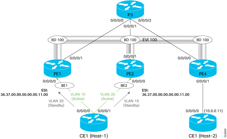


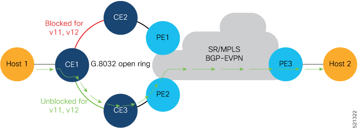
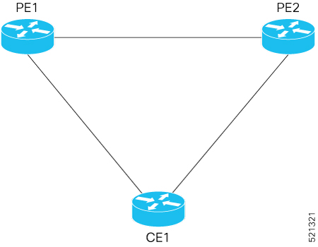

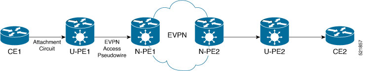
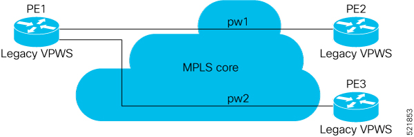

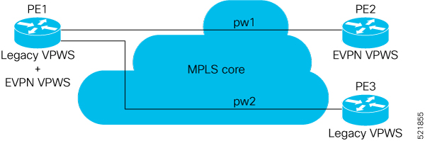
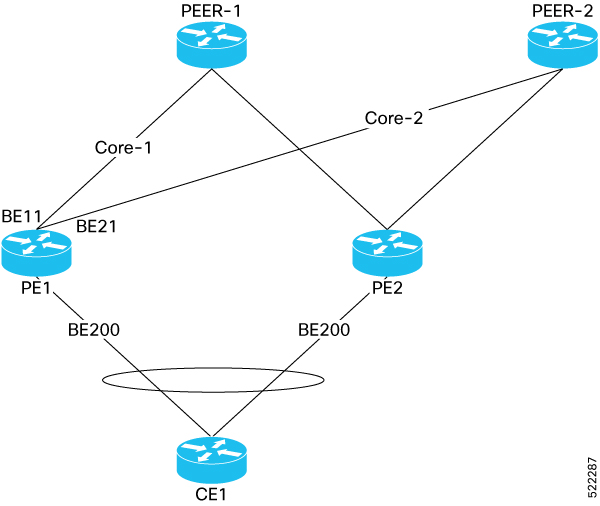


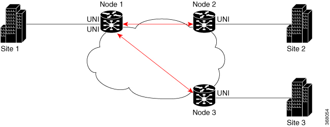
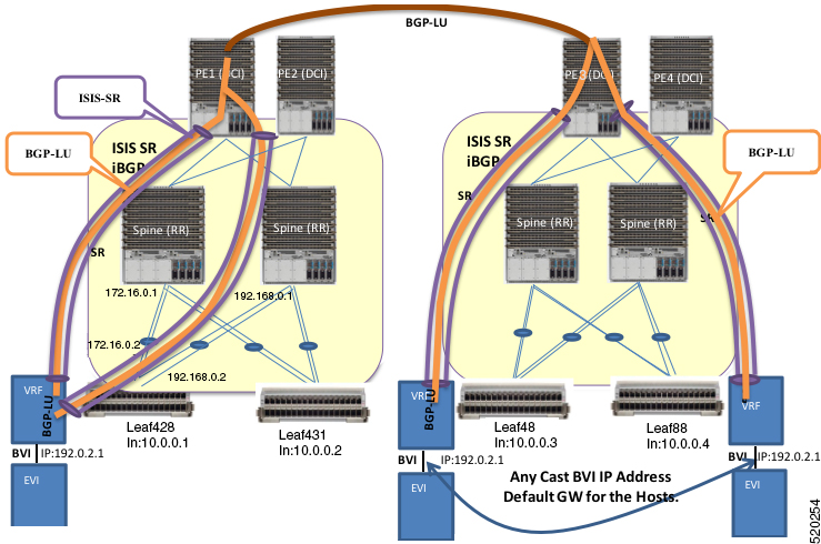
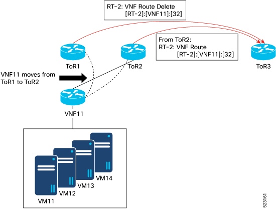
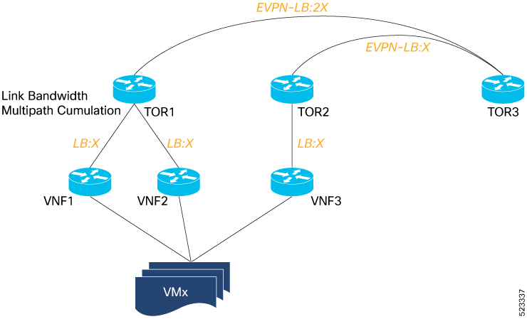
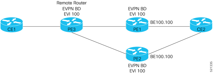
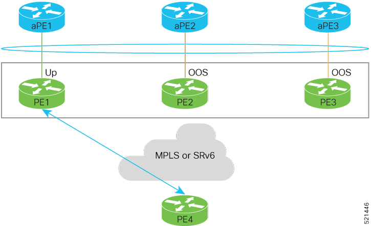
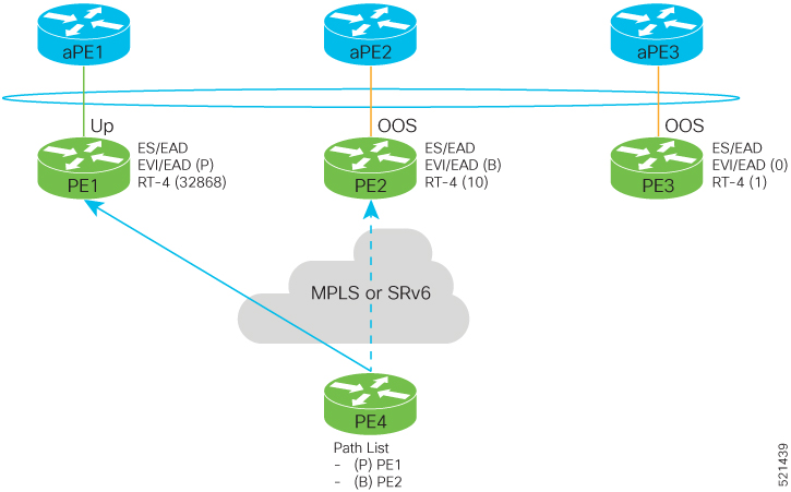
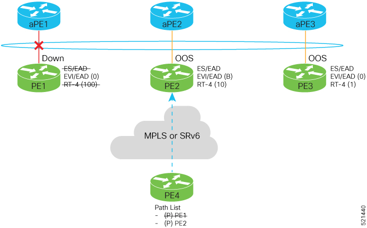
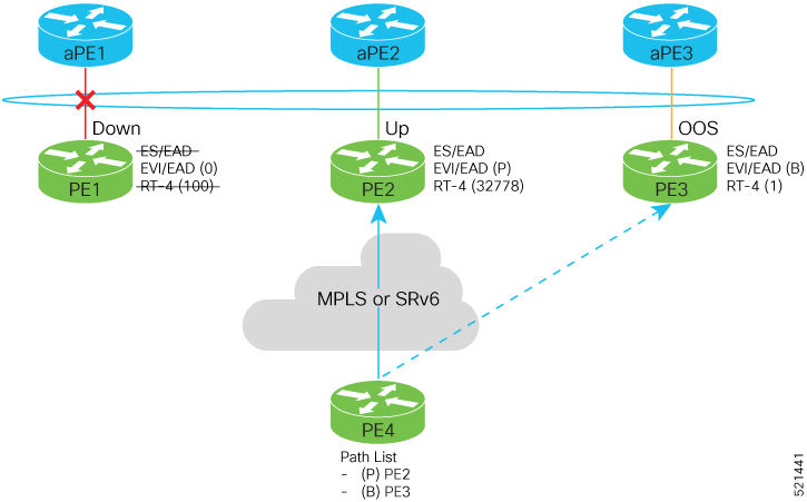
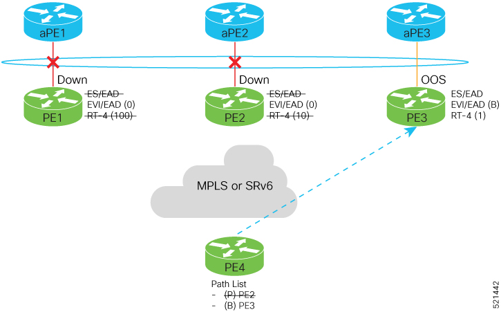

 Feedback