L2VPN and Ethernet Services Configuration Guide for Cisco NCS 5500 Series Routers, IOS XR Release 24.1.x , 24.2.x , 24.4.x
Bias-Free Language
The documentation set for this product strives to use bias-free language. For the purposes of this documentation set, bias-free is defined as language that does not imply discrimination based on age, disability, gender, racial identity, ethnic identity, sexual orientation, socioeconomic status, and intersectionality. Exceptions may be present in the documentation due to language that is hardcoded in the user interfaces of the product software, language used based on RFP documentation, or language that is used by a referenced third-party product. Learn more about how Cisco is using Inclusive Language.
The EVPN-VPWS is a BGP control plane solution for point-to-point
services. It implements the signaling and encapsulation techniques for
establishing an EVPN instance between a pair of PEs. It has the ability to
forward traffic from one network to another without MAC lookup. The use of EVPN
for VPWS eliminates the need for signaling single-segment and multi-segment PWs
for point-to-point Ethernet services. The EVPN-VPWS technology works on IP and
MPLS core; IP core to support BGP and MPLS core for switching packets between
the endpoints.
EVPN-VPWS support both single-homing
and multi-homing.
Note
When both MPLS and SRv6 are configured in the core, EVPN VPWS services cannot
co-exist with SRv6 and MPLS.
Table 1. Feature History Table
Feature Name
Release Information
Feature Description
EVPN VPWS
Release 7.3.1
This feature is now supported on Cisco NCS 5700 series fixed port routers and the Cisco NCS 5500 series routers that have
the Cisco NC57 line cards installed and operating in the native and compatible modes.
Supported Modes for EVPN-VPWS
EVPN-VPWS supports the following modes:
Single-homed - Enables you to connect a customer edge (CE) device to one provider edge (PE) device.
Multi-homed - Enables you to connect a customer edge (CE) device to more than one provider edge (PE) device. Multihoming ensures
redundant connectivity. The redundant PE device ensures that there is no traffic disruption when there is a network failure.
Following are the types of multihoming:
Single-Active - In single-active mode only a single PE among a group of PEs attached to the particular Ethernet-Segment is
allowed to forward traffic to and from that Ethernet Segment.
All-Active - In all-active mode all the PEs attached to the particular Ethernet-Segment is allowed to forward traffic to and
from that Ethernet Segment.
EVPN-VPWS Single
Homed
The EVPN-VPWS single homed solution requires per EVI Ethernet Auto
Discovery route. EVPN defines a new BGP Network Layer Reachability Information
(NLRI) used to carry all EVPN routes. BGP Capabilities Advertisement used to
ensure that two speakers support EVPN NLRI (AFI 25, SAFI 70) as per RFC 4760.
The architecture for EVPN VPWS is that the PEs run Multi-Protocol BGP in
control-plane. The following image describes the EVPN-VPWS configuration:
The VPWS service on PE1 requires the following three elements to be
specified at configuration time:
The VPN ID (EVI)
The local AC identifier (AC1) that identifies the local end of
the emulated service.
The remote AC identifier (AC2) that identifies the remote end of
the emulated service.
PE1 allocates a MPLS label per local AC for reachability.
The VPWS service on PE2 is set in the same manner as PE1. The three
same elements are required and the service configuration must be symmetric.
PE2 allocates a MPLS label per local AC for reachability.
PE1 advertise a single EVPN per EVI Ethernet AD route for each local
endpoint (AC) to remote PEs with the associated MPLS label.
PE2 performs the same task.
On reception of EVPN per EVI EAD route from PE2, PE1 adds the entry
to its local L2 RIB. PE1 knows the path list to reach AC2, for example, next
hop is PE2 IP address and MPLS label for AC2.
PE2 performs the same task.
Configure EVPN-VPWS
Single Homed
This section describes
how you can configure single-homed EVPN-VPWS feature.
The EVPN VPWS feature
supports all-active multihoming capability that enables you to connect a
customer edge device to two or more provider edge (PE) devices to provide load
balancing and redundant connectivity. The load balancing is done using
equal-cost multipath (ECMP).
When a CE device is
multi-homed to two or more PEs and when all PEs can forward traffic to and from
the multi-homed device for the VLAN, then such multihoming is referred to as
all-active multihoming.
Figure 1. EVPN VPWS
Multi-Homed
Consider the topology
in which CE1 is multi-homed to PE1 and PE2; CE2 is multi-homed to PE3 and PE4.
PE1 and PE2 will advertise an EAD per EVI route per AC to remote PEs which is
PE3 and PE4, with the associated MPLS label. The ES-EAD route is advertised per
ES (main interface), and it will not have a label. Similarly, PE3 and PE4
advertise an EAD per EVI route per AC to remote PEs, which is PE1 and PE2, with
the associated MPLS label.
Consider a traffic
flow from CE1 to CE2. Traffic is sent to either PE1 or PE2. The selection of
path is dependent on the CE implementation for forwarding over a LAG. Traffic
is encapsulated at each PE and forwarded to the remote PEs (PE 3 and PE4)
through MPLS core. Selection of the destination PE is established by flow-based
load balancing. PE3 and PE4 send the traffic to CE2. The selection of path from
PE3 or PE4 to CE2 is established by flow-based load balancing.
If there is a failure
and when the link from CE1 to PE1 goes down, the PE1 withdraws the ES-EAD
route; sends a signal to the remote PEs to switch all the VPWS service
instances associated with this multi-homed ES to backup PE, which is PE2.
Configure EVPN-VPWS Single-Active Multi-Homed
This section describes how to configure single-active multi-homed EVPN-VPWS feature. You can enable the single-active mode
by using the load-balancing-mode single-active command.
/* On PE1 */
!
configure
l2vpn xconnect group evpn_vpws
 p2p e1_5-6
  interface Bundle-Ether10.2
  neighbor evpn evi 1 target 5 source 6
!
evpn
interface Bundle-Ether10
  ethernet-segment
   identifier type 0 00.01.00.ac.ce.55.00.0a.00

!


/* On PE2 */
!
configure
l2vpn xconnect group evpn_vpws
 p2p e1_5-6
  interface Bundle-Ether10.2
  neighbor evpn evi 1 target 5 source 6
!
evpn
interface Bundle-Ether10
  ethernet-segment
   identifier type 0 00.01.00.ac.ce.55.00.0a.00

!

/* On PE3 */
!
configure
l2vpn xconnect group evpn_vpws
 p2p e1_5-6
  interface Bundle-Ether20.1
  neighbor evpn evi 1 target 6 source 5
!
evpn
interface Bundle-Ether20
  ethernet-segment
      identifier type 0 00.01.00.ac.ce.55.00.14.00

!

/* On PE4 */
!
configure
l2vpn xconnect group evpn_vpws
 p2p e1_5-6
  interface Bundle-Ether20.1
  neighbor evpn evi 1 target 6 source 5
!
evpn
interface Bundle-Ether20
  ethernet-segment
      identifier type 0 00.01.00.ac.ce.55.00.14.00

!
Flow Label Support for EVPN VPWS
The Flow Label support for EVPN VPWS feature enables provider (P) routers to use the flow-based load balancing to forward
traffic between the provider edge (PE) devices. This feature uses Flow-Aware Transport (FAT) of pseudowires (PW) over an MPLS
packet switched network for load-balancing traffic across BGP-based signaled pseudowires for Ethernet VPN (EVPN) Virtual Private
Wire Service (VPWS).
FAT PWs provide the capability to identify individual flows within a PW and provide routers the ability to use these flows
to load-balance the traffic. FAT PWs are used to load balance the traffic in the core when equal cost multipaths (ECMP) are
used. A flow label is created based on indivisible packet flows entering an imposition PE. This flow label is inserted as
the lower most label in the packet. P routers use the flow label for load balancing to provide better traffic distribution
across ECMP paths or link-bundled paths in the core. A flow is identified either by the source and destination IP address
of the traffic, or the source and destination MAC address of the traffic.
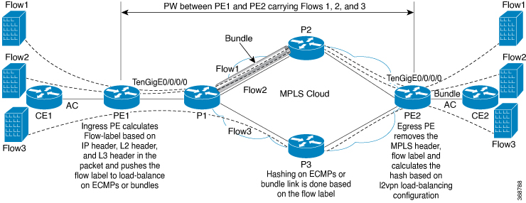
The following figure shows a FAT PW with two flows distributing over ECMPs and bundle links.
Figure 2. FAT PW with Two Flows Distributing over ECMPs and Bundle Links
An extra label is added to the stack, called the flow label, which is generated for each unique incoming flow on the PE. A
flow label is a unique identifier that distinguishes a flow within the PW, and is derived from source and destination MAC
addresses, and source and destination IP addresses. The flow label contains the end of label stack (EOS) bit set. The flow
label is inserted after the VC label and before the control word (if any). The ingress PE calculates and forwards the flow
label. The FAT PW configuration enables the flow label. The egress PE discards the flow label such that no decisions are made.
Core routers perform load balancing using the flow-label in the FAT PW with other information like MAC address and IP address.
The flow-label adds greater entropy to improve traffic load balancing. Therefore, it is possible to distribute flows over
ECMPs and link bundles.
In this topology, the imposition router, PE1, adds a flow label in the traffic. The disposition router, PE2, allows mixed
types of traffic of which some have flow label, others do not. The P router uses flow label to load balance the traffic between
the PEs. PE2 ignores the flow label in traffic, and uses one EVPN label for all unicast traffic.
Restrictions
To configure flow label for EVPN VPWS, the following restrictions are applicable:
This feature is not supported for EVPN Point-to-Multipoint (P2MP) of VPLS and Ethernet LAN (E-LAN) service.
This feature is supported only for EVPN VPWS single homing. AC bundle interfaces must be configured with ESI-0 only.
This feature is not supported for EVPN flexible cross-connect service.
This feature is not supported for EVPN VPWS multihoming.
Configure Flow Label for EVPN VPWS
Configuration Example
Perform this task to configure flow label for EVPN VPWS on both PE1 and PE2.
This section shows the running configuration of flow label for EVPN VPWS.
l2vpn
 xconnect group evpn-vpws
  p2p evpn1
   interface TenGigE0/0/0/0
   neighbor evpn evi 1 target 2 source 1
   !
  !
evpn
 evi 1
    load-balancing
   flow-label static
  !
!
Verification
Verify EVPN VPWS flow label configuration.
Router# show l2vpn xconnect detail
Group evpn-vpws, XC evpn1, state is up; Interworking none
  AC: TenGigE0/0/0/0, state is up
    Type Ethernet
    MTU 1500; XC ID 0x1; interworking none
    Statistics:
      packets: received 21757444, sent 0
      bytes: received 18226521128, sent 0
  EVPN: neighbor 100.100.100.2, PW ID: evi 1, ac-id 2, state is up ( established )
    XC ID 0xc0000001
    Encapsulation MPLS
   Encap type Ethernet, control word disabled
    Sequencing not set
    LSP : Up
    Flow Label flags configured (Tx=1,Rx=1) statically

      EVPN         Local                          Remote
      ------------ ------------------------------ -----------------------------
      Label        64002                          64002
      MTU          1500                           1500
      Control word disabled                       disabled
      AC ID        1                              2
      EVPN type    Ethernet                       Ethernet

      ------------ ------------------------------ -----------------------------
    Create time: 30/10/2018 03:04:16 (00:00:40 ago)
    Last time status changed: 30/10/2018 03:04:16 (00:00:40 ago)
    Statistics:
      packets: received 0, sent 21757444
      bytes: received 0, sent 18226521128
This feature allows you to effectively manage a network with EVPN
services running EVPN VPWS. The CFM provides proactive network
management, troubleshooting, connectivity monitoring, fault
verification, and fault isolation. This feature is supported only on
EVPN single homing mode with only one AC on the bridge domain.
This feature is now supported on routers that have Cisco NC57 line cards installed and operate in native mode only.
Connectivity fault management (CFM) is a service-level Operations and Maintenance (OAM) protocol that provides tools for monitoring
and troubleshooting end-to-end Ethernet services. This feature provides high speed Layer 2 and Layer 3 services with high
resiliency and less operational complexity to different market segments.
Supported Offload Types and Timer Values
The following are supported offload types:
Hardware (HW) Offload: The continuity check message (CCM) timers for a CFM session on a physical interface is less than 100
ms.
Non-Offload: The CCM timers for a CFM session on a physical interface is greater than 100 ms.
Software (SW) Offload: The CFM session on a bundle interface.
The following are the supported offload timer values:
3.3ms: Interval of 3.3 milliseconds
10ms: Interval of 10 milliseconds
100ms: Interval of 100 milliseconds
1s: Interval of 1 second
10s: Interval of 10 seconds
1m: Interval of 1 minute
10m: Interval of 10 minutes
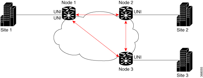
Configure CFM on EVPN VPWS
Figure 3. CFM on EVPN VPWS: Full Mesh Topology
Node 1, 2 and 3 in this topology can be Cisco routers.
Configuring CFM on EVPN VPWS involves these main tasks:
Enabling CFM service continuity check
Configuring MEP cross-check
Enabling CFM for the interface
Configuration Example
/* Enabling CFM continuity check */
Router# ethernet cfm
Router(config-cfm# domain xcup1 level 7 id null
Router(config-cfm-dmn)# service xcup1 xconnect group evpn_vpws_Bundle_ether203 p2p evpn_vpws-100 id number 4001
Router(config-cfm-dmn-svc)# mip auto-create all ccm-learning
Router(config-cfm-dmn-svc)# continuity-check interval 1s
/* Configuring MEP cross-check */
Router(config-cfm-dmn-svc)# mep crosscheck
Router(config-cfm-dmn-svc)# mep-id 4001
Router(config-cfm-dmn-svc)# commit
Repeat the above configurations for node 2 and node 3, with the respective mep-id values. For node 2, configure MEP cross-check
with respective mep-id values of node 1 and node 3 (2001 and 3001 respectively, in this example). For node 3, configure MEP
cross-check with respective mep-id values of node 1 and node 2 (4001 and 2001 respectively, in this example).
/* Enabling CFM on the interface */
Router# configure
Router(config)# interface Bundle-Ether203.2001 l2transport
Router(config-subif)# encapsulation dot1q 2001
Router(config-subif)# ethernet cfm
Router(config-if-cfm)# mep domain xcup1 service xcup1 mep-id 2001
Router(config-if-cfm-mep)# commit
You must repeat the above configurations for node 2 and node 3, with the respective mep-id values.
Running Configuration
This sections shows the running configuration on node 1.
ethernet cfm
 domain xcup1 level 7 id null
  service xcup1 xconnect group evpn_vpws_Bundle_ether203 p2p evpn_vpws-100 id number 4001
   mip auto-create all ccm-learning
   continuity-check interval 1s
   mep crosscheck
    mep-id 4001
   !
  !
 !
!
interface Bundle-Ether203.2001 l2transport
 encapsulation dot1q 2001
 ethernet cfm
  mep domain xcup1 service xcup1 mep-id 2001
 !
Y.1731 Support for EVPN-VPWS
Table 3. Feature History Table
Feature Name
Release Information
Feature Description
Y.1731 Support for EVPN-VPWS
Release 7.5.1
EVPN VPWS services support CFM continuity check, ITU-T Y.1731 compliant Delay Measurement Message (DMM) and Synthetic Loss
Measurement (SLM) functions. This feature is supported only on single-homed EVPN VPWS.
This feature is now supported on routers that have Cisco NC57 line
cards installed and operate in native mode.
DMM is used to periodically measure frame delay and frame delay variation between a pair of point-to-point Maintenance End
Point (MEPs). Measurements are made between two MEPs belonging to the same domain and Maintenance Association (MA).
SLM is used to periodically measure Frame Loss and Forward Loss Ratio (FLR) between a pair of point to point MEPs. Measurements
are made between two MEPs that belong to the same domain and MA.
Configuration Example
l2vpn
 xconnect group evpn_vpws_203
  p2p evpn_vpws_phy-100
   interface GigabitEthernet0/0/0/2.100
   neighbor evpn evi 30001 target 30001 source 50001
   !

ethernet cfm
 domain xcup1 level 7 id null
  service xcup1 xconnect group evpn_vpws_Bundle_ether203 p2p evpn_vpws-100 id number 4001
   mip auto-create all ccm-learning
   continuity-check interval 1s
   mep crosscheck
    mep-id 4001
!

interface GigabitEthernet0/0/0/2.100 l2transport
encapsulation dot1q 100
rewrite ingress tag pop 1 symmetric
mtu 9100
ethernet cfm
  mep domain bd-domain service bd-service mep-id 4001
   sla operation profile test-profile1 target mep-id 1112
!

ethernet sla
 profile EVC-1 type cfm-delay-measurement
  probe
   send packet every 1 seconds
  !
  schedule
   every 3 minutes for 120 seconds
  !
  statistics
   measure round-trip-delay
    buckets size 1 probes
    buckets archive 5
!
Private Line Emulation over EVPN-VPWS Single Homed
Table 4. Feature History Table
Feature Name
Release Information
Feature Description
Private Line Emulation over EVPN-VPWS Single Homed
Release 7.7.1
You can now configure EVPN VPWS to carry the client traffic from ports like FC, OTN, SDH, SONET, or Ethernet and forward the
traffic to the core network by using Private Line Emulation (PLE). PLE emulates the switching capabilities of FC, OTN, SDH,
SONET, or Ethernet ports without needing a dedicated equipment and allows interconnecting optical networks with Ethernet networks.
This release introduces new and modified YANG data models for PLE. For the list of supported data models, see Supported Yang Data Models for PLE. You can access these data models from the Github repository.
PLE service is a mechanism that allows the transparent transfer of packets from different port modes over MPLS networks.
PLE client traffic is carried on EVPN-VPWS single homed service. The PLE endpoints establish a BGP session to exchange EVPN
route information. The pseudowire channel is set up between the endpoints when the L2VPN cross-connect is set up between PLE
client, represented as Circuit Emulation (CEM) interface, and the remote node.
CEM helps PLE endpoints to provide native client interfaces. CEM service is a method through which data can be transmitted
over Ethernet or MPLS networks. CEM over a packet carries circuits over Packet Switched Network (PSN) placing the client bitstreams
into packet payload with appropriate pseudowire emulation headers.
PLE client traffic is encapsulated by PLE initiator and is carried over EVPN-VPWS L2 service running on segment routing or
MPLS tunnels. PLE terminator node extracts the bitstreams from the EVPN packets and places them to the PLE client interface
as defined by the client attribute and CEM profile. The traffic flow between the client and core networks happens with label
imposition and disposition.
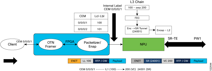
PLE Forwarding Flow – Imposition
Imposition is the process of adding an MPLS label to a data packet. A PE router forwards traffic from a client interface by
adding an MPLS label to the packet upon entering an MPLS network. When PLE forwards traffic from client to core network, label
imposition is used to forward the packets.
Figure 4. PLE Forwarding Flow – Imposition
In the diagram, traffic from client may be of any port mode like FC, OTN, SDH, SONET, or Ethernet. Field Programmable Gate
Array (FPGA) acts as a forwarding block. FPGA sends the traffic from the client towards NPU with an assigned internal local
label.
In this example, the traffic from client flows through CEM interface. The internal local label 100 is added to the CEM interface
0/0/0/1 in the FPGA.
NPU receives traffic with assigned internal local label from FPGA and in the forwarding L3 chain, replaces the internal local
label 100 with Virtual Circuit (VC) label 200. VC label is also known as the pseudowire (PW) label.
The traffic is then forwarded towards core network using the transport label 24001.
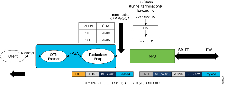
PLE Forwarding Flow – Disposition
Disposition is the process of removing an MPLS label from a data packet. A PE router receives an MPLS packet, makes a forwarding
decision based on the MPLS label, removes the label, and sends the traffic to the client. When PLE forwards traffic from core
to client network, label disposition is used to forward the packets.
Figure 5. PLE Forwarding Flow – Disposition
In the diagram, NPU receives traffic with VC label.
NPU determines the outgoing interface for the traffic, based on the VC label allocation.
The VC label 200 is replaced with the internal local label 100 and sent to FPGA.
In the FPGA, the internal local label is mapped to CEM interface 0/0/0/1 and traffic is forwarded to the client through the
CEM interface.
PLE Transport Mechanism
You can configure circuit-style segment routing to transport PLE client traffic over the networks. Circuit-style SR-TE supports
the following:
Co-router bidirectional paths
Guaranteed latency
End-to-end path protection
Guaranteed bandwidth
The circuit-style SR-TE policies are configured statically as preferred path within a pseudowire class. An SR-TE policy is
associated per pseudowire by assigning corresponding pseudowire class to working or protected pseudowires.
For more information on SR-TE policies, see the Configure SR-TE Policies section in the Segment Routing Configuration Guide for Cisco NCS 5500 Series Routers, IOS XR.
Supported Hardware for PLE
PLE is supported on NC55-OIP-02 MPA with SFP+ optical transceivers. The NC55-OIP-02 MPA supports the following port mode options:
Ethernet – 1GE and 10GE
Fiber channel (FC) – 1G, 2G, 4G, 8G, 16G, and 32G
Optical Transport Network (OTN) – OTU2 and OTU2e
Synchronous Digital Hierarchy (SDH) – STM16 and STM64
Synchronous Optical Networking (SONET) – OC48 and OC192
For more information on the MPA, see the Hardware Installation Guide for Cisco NCS 5500 Series Fixed-Port Routers .
Restrictions for PLE over EVPN VPWS
Load balancing is not supported for PLE traffic in the core, because PLE does not work with ECMP or core bundle having more
than one member link.
Software offloading is supported only on SR-TE performance monitoring and hence Fast Reroute (FRR) convergence is not possible.
PLE circuit over SR-TE tunnel with deep label stack is not supported, as this may lead to the circuit being down. For more
information on label stacking, see MPLS Configuration Guide for Cisco NCS 5500 Series Routers, IOS XR.
Note
These restrictions are applicable for IOS XR release 7.7.1.
Configure PLE over EVPN VPWS
Prerequisites
Install all the mandatory Cisco RPMS like RSVP for MPLS-TE. For more information, see the Implementing RSVP for MPLS-TE section in the MPLS Configuration Guide for Cisco NCS 5500 Series Routers, IOS XR.
Ensure that the clocks between the routers in the network is synchronized with Synchronous Ethernet (SyncE) or Precision Time
Protocol (PTP), to avoid drop in the data traffic.
Core interface bandwidth must be higher than the access interface. For example, when traffic from CE is 10G, it becomes 12.5G
when it reaches the core. Hence, the core interface bandwidth must be at least 25G.
Topology
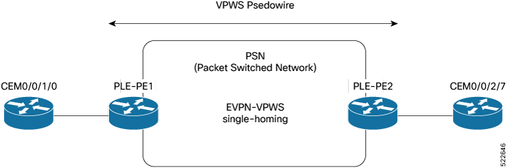
Figure 6. PLE over EVPN VPWS
In this topology, CEM interfaces are connected to PLE interfaces. The PLE interfaces, PE1 and PE2, are connected through EVPN-VPWS
single homing. The PLE interface can be: Ethernet, OTN, FC, or SONET/SDH.
Configuration Example
Perform the following tasks to configure EVPN-VPWS over SR-TE policy with explicit path. For more information on SR-TE policies,
see the Configure SR-TE Policies section in the Segment Routing Configuration Guide for Cisco NCS 5500 Series Routers, IOS XR.
Enable Frequency Synchronization to synchronize the clock between the PE routers.
Bring up the Optics Controller in CEM Packet Mode, based on the port mode type.
Configure Access and Core Interfaces.
Configure Loopback Interface to establish BGP-EVPN neighborship.
Configure IS-IS IGP to advertise the loopback and core interfaces.
Configure Performance Measurement to enable liveness monitoring of SR policy.
Configure Segment Routing Traffic Engineering Tunnels with circuit-styled SR-TE tunnels and explicit path.
Configure BGP EVPN Neighbor Session to exchange EVPN route information.
Configure EVPN VPWS with pseudowire class (PW) and cross-connect (xconnect) service to carry the PLE client traffic.
Configure QoS Policy on CEM Interface to manage congestion on PLE client traffic.
(Use the show frequency synchronization interfaces command to verify that the clock is transmitted.)
/* Enable Frequency Synchronization on PLE-PE2 */
Router(config)# frequency synchronization
Router(config-freqsync)# quality itu-t option 1
Router(config-freqsync)# exit
Router(config)# interface TwentyFiveGigE0/0/0/32
Router(config-if)# frequency synchronization
Router(config-if-freqsync)# selection input
Router(config-if-freqsync)# priority 1
Router(config-if-freqsync)# wait-to-restore 0
!
(Use the show frequency synchronization selection command to verify if PLE-PE2 is LOCKED to PLE-PE1's clock.)
Bring up the Optics Controller in CEM Packet Mode
Configure the optics controller and port mode. The examples show port mode configuration for all the types of port modes.
Use the relevant command according to the port mode type of the PLE interface.
/* Bring up the optics controller in CEM packet mode with appropriate speed on PLE-PE1 */
Configure IS-IS IGP to advertise the configured loopback and core interfaces.
Note
You cannot configure Topology-Independent Loop-Free Alternate (TI-LFA) on the links used by circuit-styled SR-TE tunnel. The
adjacency SID label is unprotected for circuit-styled SR-TE, which does not support TI-LFA.
Configure circuit-styled SR-TE tunnels. SR-TE is supported only with explicit path specified by adjacency SID labels. The
adjacency SID labels must be unprotected for circuit-styled SR-TE. This example shows configuration of explicit path between
PE1 and PE2.
/* Configure segment routing traffic engineering tunnels on PLE-PE1 */
Configure QoS policy to manage congestion on PLE client traffic. In QoS for PLE, you can mark the MPLS experimental with only
the topmost label and set the traffic class with only the default class.
/* Configure QoS policy on PLE-PE1 */
Access Interface Configuration
Router(config)# policy-map ple-policy
Router(config-pmap)# class class-default
Router(config-pmap-c)# set mpls experimental topmost 7
Router(config-pmap-c)# set traffic-class 2
Router(config-pmap-c)# end-policy-map
!

Router(config)# interface CEM0/0/1/0
Router(config-if)# l2transport
Router(config-if)# service-policy input ple-policy
!
!
Use the following show commands to view the configuration.
Verify the IS-IS configuration.
Router# show isis neighbors
Fri Nov 12 09:04:13.638 UTC

IS-IS core neighbors:
System Id      Interface        SNPA           State Holdtime Type IETF-NSF
PLE-Core-PE2   TF0/0/0/24       *PtoP*         Up    28       L2   Capable

Total neighbor count: 1
Router# show isis segment-routing label table
Fri Nov 12 09:25:18.488 UTC
IS-IS core IS Label Table
Label Prefix Interface
---------- ---------------- ---------
16001 1.1.1.1/32Loopback0
16004 1.1.1.4/32
Router# show mpls forwarding prefix 1.1.1.4/32
Fri Nov 12 09:25:54.898 UTC
Local  Outgoing    Prefix             Outgoing     Next Hop        Bytes
Label  Label       or ID              Interface                    Switched
------ ----------- ------------------ ------------ --------------- ------------
16004  Pop         SR Pfx (idx 4)     TF0/0/0/24   14.1.0.2        104332
Verify the performance measurement.
Router# show performance-measurement sr-policy color 203
Mon Mar 14 17:54:32.403 IST

------------------------------------------------------------------
0/RP0/CPU0
------------------------------------------------------------------

SR Policy name: srte_c_203_ep_1.1.1.1
Color : 203
Endpoint : 1.1.1.1
Number of candidate-paths : 1

Candidate-Path:
Instance : 8
Preference : 10
Protocol-origin : Configured
Discriminator : 10
Profile Keys:
Profile name : BLUE
Profile type : SR Policy Liveness Detection
Source address : 1.1.1.6
Number of segment-lists : 1
Liveness Detection: Enabled
Session State: Up
Last State Change Timestamp: Mar 14 2022 17:53:45.207
Missed count: 0

---------------------------------------------------------------------
0/0/CPU0
---------------------------------------------------------------------
Verify SR-TE configuration.
Router# show segment-routing traffic-eng policy color 10 tabular
Fri Nov 12 09:15:57.366 UTC
Color Endpoint AdminOper Binding
StateState SID
------ --------------------------------------- ------ ------ -----------------------
10 1.1.1.4 upup 24010
Verify BGP EVPN neighbor session configuration.
Router# show bgp l2vpn evpn neighbors brief
Fri Nov 12 09:10:22.999 UTC

Neighbor        Spk    AS Description                          Up/Down  NBRState
1.1.1.4           0   100                                      15:51:52 Established
Verify EVPN VPWS configuration.
Router# show l2vpn xconnect
Fri Nov 12 09:02:44.982 UTC
Legend: ST = State, UP = Up, DN = Down, AD = Admin Down, UR = Unresolved,
        SB = Standby, SR = Standby Ready, (PP) = Partially Programmed,
        LU = Local Up, RU = Remote Up, CO = Connected, (SI) = Seamless Inactive

XConnect                   Segment 1                       Segment 2
Group      Name       ST   Description            ST       Description            ST
----------------------------------------------------------------------------------------
evpn_vpws  p1         UP   CE0/0/1/0              UP       EVPN 10,1,24012        UP
----------------------------------------------------------------------------------------
Verify QoS policy configuration.
The following show command displays information about interfaces on which the policy maps are applied.
Router# show policy-map targets
Thu Jun 16 21:47:31.407 IST
1) Policymap: ple-p1 Type: qos
Targets (applied as main policy):
CEM0/0/1/0 input
Total targets: 1

Targets (applied as child policy):
Total targets: 0

2) Policymap: core Type: qos
Targets (applied as main policy):
TwentyFiveGigE0/0/0/24
Total targets: 1

Targets (applied as child policy):
Total targets: 0
Use the following show command to view the core interface information and to verify the traffic class (TC) mapping in CEM
interface.
Router# Show policy-map interface TwentyFiveGigE0/0/0/24
Thu Jun 16 21:37:52.915 IST
TwentyFiveGigE0/0/0/24 direction input: Service Policy is not installed
TwentyFiveGigE0/0/0/24 output: core
Class tc2
    Classification Statistics    (packets/bytes)          (rate - kbps)
        Matched           :      39654778/42113374236        6816279
        Transmitted       :      39654778/42113374236        6816279
        Total Dropped     :             0/0                  0
    Queueing Statistics
        Queue ID                      : 1370
        Taildropped(packets/bytes)    : 0/0
Class class-default
    Classification Statistics    (packets/bytes)          (rate - kbps)
        Matched           :             0/0                  0
        Transmitted       :             0/0                  0
        Total Dropped     :             0/0                  0
    Queueing Statistics
        Queue ID                      : 1368
        Taildropped(packets/bytes)    : 0/0
Policy Bag Stats time: 1655395669491    [Local Time: 06/16/22 21:37:49:491]
Supported Yang Data Models for PLE
The following is the list of new and modified Yang data models supported for PLE. You can access the data models from the
Github repository.


 Feedback