Routing Configuration Guide for Cisco NCS 5500 Series Routers, IOS XR Release 24.1.x, 24.2.x, 24.3.x, 24.4.x
Bias-Free Language
The documentation set for this product strives to use bias-free language. For the purposes of this documentation set, bias-free is defined as language that does not imply discrimination based on age, disability, gender, racial identity, ethnic identity, sexual orientation, socioeconomic status, and intersectionality. Exceptions may be present in the documentation due to language that is hardcoded in the user interfaces of the product software, language used based on RFP documentation, or language that is used by a referenced third-party product. Learn more about how Cisco is using Inclusive Language.
The Enhanced Interior Gateway Routing Protocol (EIGRP) is an enhanced version of IGRP developed by Cisco. This module describes
the concepts and tasks you need to implement basic EIGRP configuration using Cisco IOS XR software. EIGRP uses distance vector
routing technology, which specifies that a router need not know all the router and link relationships for the entire network.
Each router advertises destinations with a corresponding distance and upon receiving routes, adjusts the distance and propagates
the information to neighboring routes.
Implementing EIGRP
The Enhanced Interior Gateway Routing Protocol (EIGRP) is an enhanced version of IGRP developed by Cisco. This module describes
the concepts and tasks you need to implement basic EIGRP configuration using Cisco IOS XR software. EIGRP uses distance vector
routing technology, which specifies that a router need not know all the router and link relationships for the entire network.
Each router advertises destinations with a corresponding distance and upon receiving routes, adjusts the distance and propagates
the information to neighboring routes.
This module describes how to implement EIGRP on your Cisco IOS XR network.
Restrictions for Implementing EIGRP
The following restrictions are employed when running EIGRP on this version of Cisco IOS XR software:
A maximum of 4 instances of an EIGRP process is supported.
The characters allowed for EIGRP process name are @ . # : - _ only.
Simple Network Management Protocol (SNMP) MIB is not supported.
Interface static routes are not automatically redistributed into EIGRP, because there are no network commands.
Metric configuration (either through the default-metric command or a route policy) is required for redistribution of connected and static routes.
Auto summary is disabled by default.
Stub leak maps are not supported.
Information About Implementing EIGRP
To implement EIGRP, you need to understand the following concepts:
EIGRP Functional Overview
Enhanced Interior Gateway Routing Protocol (EIGRP) is an interior gateway protocol suited for many different topologies and
media. EIGRP scales well and provides extremely quick convergence times with minimal network traffic.
EIGRP has very low usage of network resources during normal operation. Only hello packets are transmitted on a stable network.
When a change in topology occurs, only the routing table changes are propagated and not the entire routing table. Propagation
reduces the amount of load the routing protocol itself places on the network. EIGRP also provides rapid convergence times
for changes in the network topology.
The distance information in EIGRP is represented as a composite of available bandwidth, delay, load utilization, and link
reliability with improved convergence properties and operating efficiency. The fine-tuning of link characteristics achieves
optimal paths.
The convergence technology that EIGRP uses is based on research conducted at SRI International and employs an algorithm referred
to as the Diffusing Update Algorithm (DUAL). This algorithm guarantees loop-free operation at every instant throughout a route
computation and allows all devices involved in a topology change to synchronize at the same time. Routers that are not affected
by topology changes are not involved in recomputations. The convergence time with DUAL rivals that of any other existing routing
protocol.
EIGRP v4/v6 Authentication Using Keychain
EIGRP authentication using keychain introduces the capability to authenticate EIGRP protocol packets on a per-interface basis.
The EIGRP routing authentication provides a mechanism to authenticate all EIGRP protocol traffic on one or more interfaces,
based on Message Digest 5 (MD5) authentication.
The EIGRP routing authentication uses the Cisco IOS XR software security keychain infrastructure to store and retrieve secret
keys and to authenticate incoming and outgoing traffic on a per-interface basis.
Configure an Authentication Keychain
Configure an Authentication Keychain for an IPv4/IPv6 Interface on a Default VRF
Configure Route Summarization for an EIGRP Process
This task configures route summarization for an EIGRP process.
You can configure a summary aggregate address for a specified interface. If any more specific routes are in the routing table,
EIGRP advertises the summary address from the interface with a metric equal to the minimum of all more specific routes.
Note
You should not use the summary-address summarization command to generate the default route (0.0.0.0) from an interface. This command creates an EIGRP summary default
route to the null 0 interface with an administrative distance of 5. The low administrative distance of this default route
can cause this route to displace default routes learned from other neighbors from the routing table. If the default route
learned from the neighbors is displaced by the summary default route or the summary route is the only default route present,
all traffic destined for the default route does not leave the router; instead, this traffic is sent to the null 0 interface,
where it is dropped.
The recommended way to send only the default route from a given interface is to use a route-policy command.
Perform the task to configure the distribution and remote routers to use an EIGRP process for stub routing.
Note
EIGRP stub routing should be used only on remote routers. A stub router is defined as a router connected to the network core
or distribution layer through which core transit traffic should not flow. A stub router should not have any EIGRP neighbors
other than distribution routers. Ignoring this restriction causes undesirable behavior.
EIGRP typically broadcasts or multicasts routing updates. For security reasons, you can opt to configure static neighbors
in the EIGRP routing process, forcing EIGRP to communicate to specified neighbors using unicast. When you specify a static
neighbor relationship over a particular interface, EIGRP disables the processing of multicast EIGRP packets on the specified
interface. This ensures that EIGRP does not send nor process received multicast EIGRP traffic on an interface which has a
static neighbor defined under the EIGRP routing process.
In cases where the neighbors are not adjacent, normal EIGRP peering mechanisms cannot be used to exchange EIGRP information.
In order to support this type of network, EIGRP provides the neighbor command, which allows remote neighbors to be configured
and sessions established though unicast packet transmission. However, as the number of forwarders needing to exchange EIGRP
information over the networking cloud increases, unicast EIGRP neighbor definitions may become cumbersome to manage. Each
neighbor must be manually configured, resulting in increased operational costs. To better accommodate deployment of these
topologies, ease configuration management, and reduce operational costs, the Dynamic Neighbors feature provides support for
the dynamic discovery of remote unicast (referred to as “remote neighbors”). Remote neighbor support allows EIGRP peering
to one or more remote neighbors, which may not be known at the time the device is configured, thus reducing configuration
management.
In the topology illustrated below, ASA behaves as a hub and the other routers (2921s, 7010s) act as spokes. The 2921's and
7010's must not peer with each other, and there must never be a time where a packet (data traffic) is routed in this path:
ASA > 2921.3 > 2921.4. To support this type of network, EIGRP allows you to configure static neighbors and establish sessions
using unicast packet transmission. Thus, in this topology, 2921s and 7010s peer with ASA using neighbor command and ASA is
configured to dynamically discover remote neighbors.
Remote Neighbor Session Policy
When using remote unicast-listen or remote multicast-group neighbor configurations, EIGRP neighbor IP addresses are not predefined,
and neighbors may be many hops away. A device with this configuration could peer with any device that sends a valid HELLO
packet. Because of security considerations, this open aspect requires policy capabilities to limit peering to valid devices
and to restrict the number of neighbors in order to limit resource consumption. This capability is accomplished using the
following manually configured parameters, and takes effect immediately.
Neighbor Filter ListThe optional allow-list keyword, available in the remote-neighbors command, enables you to use an access list (access control
list) to specify the remote IP addresses from which EIGRP neighbor connections may be accepted. If you do not use the allow-list
keyword, then all IP addresses (permit any) will be accepted. The access control list (ACL) defines a range of IPv4 or IPv6
IP addresses with the following conditions:
Any neighbor that has a source IP address that matches an IP address in the access list will be allowed (or denied) based
on the user configuration.
If the allow-list keyword is not specified, any IP address will be permitted (permit any).
The allow-list keyword is supported only for remote multicast-group and unicast-listen neighbors. It is not available for
static, remote static, or local neighbors.
Incoming EIGRP packets that do not match the specified access list will be rejected.
Maximum Remote NeighborsThe optional max-neighbors keyword, available in the remote-neighbors command, enables you to specify a maximum number of
remote neighbors that EIGRP can create using the remote neighbor configurations. When the maximum number of remote neighbors
has been created for a configuration, EIGRP rejects all subsequent connection attempts for that configuration. This option
helps to protect against denial-of-service attacks that attempt to create many remote neighbors in an attempt to overwhelm
device resources. The max-neighbors configuration option has the following conditions:
This option is supported only for remote multicast-group or unicast-listen neighbors. It is not available for local, static,
or remote static neighbors.
There is no default maximum. If you do not specify a maximum number of remote neighbors, the number of remote neighbors is
limited only by available memory and bandwidth.
Reducing the maximum number of remote neighbors to less than the current number of sessions will result in the neighbors (in
no specific order) being dropped until the count reaches the new limit.
Configuration Changes for the Neighbor Filter List and Maximum Number of Remote Neighbors
When the allow-list or max-neighbors configurations are changed, any existing remote EIGRP sessions that are no longer allowed
by the new configuration will be removed automatically and immediately. Pre-existing neighbors that are still allowed by the
new configuration will not be affected.
Understanding Neighbor Terms
The following terms are used when describing neighbor types:
local neighbor: A neighbor that is adjacent on a shared subnet (or common subnet) and uses a link-local multicast address for packet exchange.
This is the default type of neighbor in EIGRP.
static Neighbor: Any neighbor that uses unicast to communicate, is one hop away, is on a common subnet, and whose IP address has been specified
using the neighbor ip-address command.
remote neighbor: Any neighbor that is multiple hops away, including Remote Static Neighbors.
remote group: Any neighbor that is multiple hops away, does not have its address manually configured with the neighbor command and uses
the multicast group address for packet exchange.
remote static neighbor: Any neighbor that uses unicast to communicate, is multiple hops away, and whose IP address has been specified using the neighbor
ip-address command.
remote unicast-listen (or simply unicast-listen): Any neighbor that uses unicast to communicate, is multiple hops away, and whose IP address has not been configured using
the neighbor ip-address command.
remote dnyamic: Any neighbor that is multiple hops away and whose address has not been configured with the neighbor ip-address command, that
is, a remote multicast-group or remote unicast-listen neighbor, but not a remote static neighbor.
Remote Unicast-Listen (Point-to-Point) Neighbors
For configurations in which multiple remote neighbors peer with a single hub (point-to-point), the hub can be configured for
remote unicast-listen peering using the remote-neighbors command to allow the remote neighbors to peer with the hub without
having to manually configure the remote neighbor IP addresses on the hub. When configured with this command, the hub device:
Uses its interface IP address as the source IP address for any unicast transmissions. This IP address must be routable.
Requires neighbors that peer with the hub to be configured using the neighbor ip-address loopback loopback-interface-number
remote maximum-hops command where ip-address is the unicast address of the local device interface.
Listens for unicast HELLO packets on the interface specified in the remote-neighbor command.
Accepts a unicast HELLO packet if it is in the IP address range configured using the allow-list keyword, or any unicast HELLO
packet if an allow list is not defined.
Rejects multicast HELLO packets from any neighbor that is also sending unicast HELLO packets and is permitted by the unicast
allow list (or all neighbors if an allow list is not defined).
Begins normal neighbor establishment using the IP addresses of the remote neighbors for packet transmission once the neighbor
relationship is established.
When remote-neighbor command is configured on an interface, the router will only start sending HELLOs on that interface if
it has atleast one neighbor and only to those neighbors from which it has received HELLOs.
On an interface if dynamic neighbors already exist and remote-neighbor unicast- listen is configured, then the existing neighbor
relationships will be torn down and only unicast-neighbor relationships will be allowed there after.
Restrictions for remote neighbors
A single unicast address can only be configured to a single remote static neighbor for a given address-family. You cannot
configure a second remote static neighbor using the same unicast address, on a different interface. EIGRP configuration of
remote neighbors under different address families is unrestricted.
A single interface can be configured under a single address family with a single unicast-listen remote-neighbors command
and with any number of static and remote static neighbors (each using a different unicast address).
Inheritance and precedence of the remote neighbor configurations
Static neighbors configured with the neighbor <address> or neighbor <address> remote commands take precedence over the remote neighbors created as a result of the remote-neighbors command. If the remote
address of an incoming unicast EIGRP connection matches both a static neighbor and the remote unicast-listen neighbor access
list, the static neighbor is used and no remote unicast-listen neighbor is created. If you configure a new static neighbor
while a remote neighbor for the same remote address already exists, EIGRP automatically removes the remote unicast-listen
neighbor.
EIGRP Features
EIGRP offers the following features:
Fast convergence—The DUAL algorithm allows routing information to converge as quickly as any currently available routing protocol.
Partial updates—EIGRP sends incremental updates when the state of a destination changes, instead of sending the entire contents
of the routing table. This feature minimizes the bandwidth required for EIGRP packets.
Neighbor discovery mechanism—This is a simple hello mechanism used to learn about neighboring routers. It is protocol independent.
Variable-length subnet masks (VLSMs).
Arbitrary route summarization.
Scaling—EIGRP scales to large networks.
The following key features are supported in the Cisco IOS XR implementation:
Support for IPv4 and IPv6 address families.
Provider Edge (PE)-Customer Edge (CE) protocol support with Site of Origin (SoO) and Border Gateway Protocol (BGP) cost community
support.
PECE protocol support for MPLS.
EIGRP Components
EIGRP has the following four basic components:
Neighbor discovery or neighbor recovery
Reliable transport protocol
DUAL finite state machine
Protocol-dependent modules
Neighbor discovery or neighbor recovery is the process that routers use to dynamically learn of other routers on their directly
attached networks. Routers must also discover when their neighbors become unreachable or inoperative. Neighbor discovery or
neighbor recovery is achieved with low overhead by periodically sending small hello packets. As long as hello packets are
received, the Cisco IOS XR software can determine that a neighbor is alive and functioning. After this status is determined, the neighboring routers can exchange
routing information.
The reliable transport protocol is responsible for guaranteed, ordered delivery of EIGRP packets to all neighbors. It supports intermixed transmission of multicast and unicast packets. Some EIGRP packets must be sent reliably and others need not be. For efficiency, reliability is provided only when necessary.
For example, on a multiaccess network that has multicast capabilities (such as Ethernet) it is not necessary to send hello
packets reliably to all neighbors individually. Therefore, EIGRP sends a single multicast hello with an indication in the
packet informing the receivers that the packet need not be acknowledged. Other types of packets (such as updates) require
acknowledgment, which is indicated in the packet. The reliable transport has a provision to send multicast packets quickly
when unacknowledged packets are pending. This provision helps to ensure that convergence time remains low in the presence
of various speed links.
The DUAL finite state machine embodies the decision process for all route computations. It tracks all routes advertised by
all neighbors. DUAL uses the distance information (known as a metric) to select efficient, loop-free paths. DUAL selects routes
to be inserted into a routing table based on a calculation of the feasibility condition. A successor is a neighboring router
used for packet forwarding that has a least-cost path to a destination that is guaranteed not to be part of a routing loop.
When there are no feasible successors but there are neighbors advertising the destination, a recomputation must occur. This
is the process whereby a new successor is determined. The amount of time required to recompute the route affects the convergence
time. Recomputation is processor intensive; it is advantageous to avoid unneeded recomputation. When a topology change occurs,
DUAL tests for feasible successors. If there are feasible successors, it uses any it finds to avoid unnecessary recomputation.
The protocol-dependent modules are responsible for network layer protocol-specific tasks. An example is the EIGRP module,
which is responsible for sending and receiving EIGRP packets that are encapsulated in IP. It is also responsible for parsing
EIGRP packets and informing DUAL of the new information received. EIGRP asks DUAL to make routing decisions, but the results
are stored in the IP routing table. EIGRP is also responsible for redistributing routes learned by other IP routing protocols.
EIGRP Configuration Grouping
Cisco IOS XR Software groups all EIGRP configuration under router EIGRP configuration mode, including interface configuration
portions associated with EIGRP. To display EIGRP configuration in its entirety, use the show running-config router eigrp command. The command output displays the running configuration for the configured EIGRP instance, including the interface
assignments and interface attributes.
EIGRP Configuration Modes
The following examples show how to enter each of the configuration modes. From a mode, you can enter the ? command to display the commands available in that mode.
Router Configuration Mode
The following example shows how to enter router configuration mode:
EIGRP interfaces can be configured as either of the following types:
Active—Advertises connected prefixes and forms adjacencies. This is the default type for interfaces.
Passive—Advertises connected prefixes but does not form adjacencies. The passive command is used to configure interfaces as passive. Passive interfaces should be used sparingly for important prefixes, such
as loopback addresses, that need to be injected into the EIGRP domain. If many connected prefixes need to be advertised, then
the redistribution of connected routes with the appropriate policy should be used instead.
MPLS VPN Support for EIGRP Between PE and CE
The MPLS VPN Support for EIGRP Between PE and CE feature allows service providers to configure the Enhanced Interior Gateway
Routing Protocol (EIGRP) between provider edge (PE) and customer edge (CE) devices in a Multiprotocol Label Switching (MPLS)
virtual private network (VPN) and offer MPLS VPN services to those customers that require native support for EIGRP. An MPLS
VPN consists of a set of sites that are interconnected by an MPLS provider core network. At each customer site, one or more
CE devices attach to one or more PE devices.
Redistribution for an EIGRP Process
Routes from other protocols can be redistributed into EIGRP. A route policy can be configured along with the redistribute command. A metric is required, configured either through the default-metric command or under the route policy configured with the redistribute command to import routes into EIGRP.
A route policy allows the filtering of routes based on attributes such as the destination, origination protocol, route type,
route tag, and so on. When redistribution is configured under a VRF, EIGRP retrieves extended communities attached to the route in the routing information
base (RIB). The SoO is used to filter out routing loops in the presence of MPLS VPN backdoor links.
Redistribute Routes for EIGRP
This task explains how to redistribute routes and apply limits on the number of routes. .
Create a Route Policy and Attach it to an EIGRP Process
This task defines a route policy and shows how to attach it to an EIGRP process.
A route policy definition consists of the route-policy command and name argument followed by a sequence of optional policy statements, and then closed with the end-policy command.
A route policy is not useful until it is applied to routes of a routing protocol.
Perform this task to redistribute BGP routes into EIGRP.
Typically, EIGRP routes are redistributed into BGP with extended community information appended to the route. BGP carries
the route over the VPN backbone with the EIGRP-specific information encoded in the BGP extended community attributes. After
the peering customer site receives the route, EIGRP redistributes the BGP route then extracts the BGP extended community information
and reconstructs the route as it appeared in the original customer site.
When redistributing BGP routes into EIGRP, the receiving provider edge (PE) EIGRP router looks for BGP extended community
information. If the information is received, it is used to recreate the original EIGRP route. If the information is missing,
EIGRP uses the configured default metric value.
If the metric values are not derived from the BGP extended community and a default metric is not configured, the route is
not advertised to the customer edge (CE) router by the PE EIGRP. When BGP is redistributed into BGP, metrics may not be added
to the BGP prefix as extended communities; for example, if EIGRP is not running on the other router. In this case, EIGRP is
redistributed into BGP with a “no-metrics” option.
EIGRP uses the minimum bandwidth on the path to a destination network and the total delay to compute routing metrics. You
can use the metric weights command to adjust the default behavior of EIGRP routing and metric computations. For example, this adjustment allows you
to tune system behavior to allow for satellite transmission. EIGRP metric defaults have been carefully selected to provide
optimal performance in most networks.
By default, the EIGRP composite metric is a 32-bit quantity that is a sum of the segment delays and lowest segment bandwidth
(scaled and inverted) for a given route. For a network of homogeneous media, this metric reduces to a hop count. For a network
of mixed media (FDDI, Ethernet, and serial lines running from 9600 bits per second to T1 rates), the route with the lowest
metric reflects the most desirable path to a destination.
Mismatched K Values
Mismatched K values (EIGRP metrics) can prevent neighbor relationships from being established and can negatively impact network
convergence. The following example explains this behavior between two EIGRP peers (ROUTER-A and ROUTER-B).
The following error message is displayed in the console of ROUTER-B because the K values are mismatched:
Router/CPU0:Mar 13 08:19:55:eigrp[163]:%ROUTING-EIGRP-5-NBRCHANGE:IP-EIGRP(0) 1:Neighbor 11.0.0.20 (GigabitEthernet0/6/0/0) is down: K-value mismatch
Two scenarios occur in which this error message can be displayed:
The two routers are connected on the same link and configured to establish a neighbor relationship. However, each router is
configured with different K values.
The following configuration is applied to ROUTER-A. The K values are changed with the metric weights command. A value of 2 is entered for the k1 argument to adjust the bandwidth calculation. The value of 1 is entered for the k3 argument to adjust the delay calculation.
The following configuration is applied to ROUTER-B. However, the metric weights command is not applied and the default K values are used. The default K values are 1, 0, 1, 0, and 0.
The bandwidth calculation is set to 2 on ROUTER-A and set to 1 (by default) on ROUTER-B. This configuration prevents these
peers from forming a neighbor relationship.
The K-value mismatch error message can also be displayed if one of the two peers has transmitted a “goodbye” message and the
receiving router does not support this message. In this case, the receiving router interprets this message as a K-value mismatch.
Goodbye Message
The goodbye message is a feature designed to improve EIGRP network convergence. The goodbye message is broadcast when an EIGRP
routing process is shut down to inform adjacent peers about the impending topology change. This feature allows supporting
EIGRP peers to synchronize and recalculate neighbor relationships more efficiently than would occur if the peers discovered
the topology change after the hold timer expired.
The following message is displayed by routers that run a supported release when a goodbye message is received:
Router/CPU0:Mar 13 09:13:17:eigrp[163]:%ROUTING-EIGRP-5-NBRCHANGE: IP-EIGRP(0) 1: Neighbor 10.0.0.20 (GigabitEthernet0/6/0/0) is down: Interface Goodbye received
A Cisco router that runs a software release that does not support the goodbye message can misinterpret the message as a K-value
mismatch and display the following message:
The receipt of a goodbye message by a nonsupporting peer does not disrupt normal network operation. The nonsupporting peer
terminates the session when the hold timer expires. The sending and receiving routers reconverge normally after the sender
reloads.
Percentage of Link Bandwidth Used for EIGRP Packets
By default, EIGRP packets consume a maximum of 50 percent of the link bandwidth, as configured with the bandwidth interface configuration command. You might want to change that value if a different level of link utilization is required
or if the configured bandwidth does not match the actual link bandwidth (it may have been configured to influence route metric
calculations).
Floating Summary Routes for an EIGRP Process
You can also use a floating summary route when configuring the summary-address command. The floating summary route is created by applying a default route and administrative distance at the interface level.
The following scenario illustrates the behavior of this enhancement.
The figure Floating Summary Route is Applied to Router-B shows a network with three routers, Router-A, Router-B, and Router-C. Router-A learns a default route from elsewhere in the
network and then advertises this route to Router-B. Router-B is configured so that only a default summary route is advertised
to Router-C. The default summary route is applied to interface 0/1 on Router-B with the following configuration:
Figure 1. Floating Summary Route Is Applied to Router-B
The configuration of the default summary route on Router-B sends a 0.0.0.0/0 summary route to Router-C and blocks all other
routes, including the 10.1.1.0/24 route, from being advertised to Router-C. However, this configuration also generates a local
discard route on Router-B, a route for 0.0.0.0/0 to the null 0 interface with an administrative distance of 5. When this route
is created, it overrides the EIGRP learned default route. Router-B is no longer able to reach destinations that it would normally
reach through the 0.0.0.0.0/0 route.
This problem is resolved by applying a floating summary route to the interface on Router-B that connects to Router-C. The
floating summary route is applied by relating an administrative distance to the default summary route on the interface of
Router-B with the following statement:
The administrative distance of 250, applied in the above statement, is now assigned to the discard route generated on Router-B.
The 0.0.0.0/0, from Router-A, is learned through EIGRP and installed in the local routing table. Routing to Router-C is restored.
If Router-A loses the connection to Router-B, Router-B continues to advertise a default route to Router-C, which allows traffic
to continue to reach destinations attached to Router-B. However, traffic destined for networks to Router-A or behind Router-A
is dropped when the traffic reaches Router-B.
The figure Floating Summary Route is Applied for Dual-Homed Remotes shows a network with two connections from the core: Router-A and Router-D. Both routers have floating summary routes configured
on the interfaces connected to Router-C. If the connection between Router-E and Router-C fails, the network continues to operate
normally. All traffic flows from Router-C through Router-B to the hosts attached to Router-A and Router-D.
Figure 2. Floating Summary Route Applied for Dual-Homed Remotes
However, if the link between Router-D and Router-E fails, the network may dump traffic into a black hole because Router-E
continues to advertise the default route (0.0.0.0/0) to Router-C, as long as at least one link (other than the link to Router-C)
to Router-E is still active. In this scenario, Router-C still forwards traffic to Router-E, but Router-E drops the traffic
creating the black hole. To avoid this problem, you should configure the summary address with an administrative distance on
only single-homed remote routers or areas in which only one exit point exists between the segments of the network. If two
or more exit points exist (from one segment of the network to another), configuring the floating default route can cause a
black hole to form.
Split Horizon for an EIGRP Process
Split horizon controls the sending of EIGRP update and query packets. When split horizon is enabled on an interface, update
and query packets are not sent for destinations for which this interface is the next hop. Controlling update and query packets
in this manner reduces the possibility of routing loops.
By default, split horizon is enabled on all interfaces.
Split horizon blocks route information from being advertised by a router on any interface from which that information originated.
This behavior usually optimizes communications among multiple routing devices, particularly when links are broken. However,
with nonbroadcast networks (such as Frame Relay and SMDS), situations can arise for which this behavior is less than ideal.
For these situations, including networks in which you have EIGRP configured, you may want to disable split horizon.
Adjustment of Hello Interval and Hold Time for an EIGRP Process
You can adjust the interval between hello packets and the hold time.
Routing devices periodically send hello packets to each other to dynamically learn of other routers on their directly attached
networks. This information is used to discover neighbors and learn when neighbors become unreachable or inoperative. By default,
hello packets are sent every 5 seconds.
You can configure the hold time on a specified interface for a particular EIGRP routing process designated by the autonomous
system number. The hold time is advertised in hello packets and indicates to neighbors the length of time they should consider
the sender valid. The default hold time is three times the hello interval, or 15 seconds.
Stub Routing for an EIGRP Process
The EIGRP Stub Routing feature improves network stability, reduces resource usage, and simplifies stub router configuration.
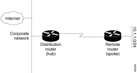
Stub routing is commonly used in a hub-and-spoke network topology. In a hub-and-spoke network, one or more end (stub) networks
are connected to a remote router (the spoke) that is connected to one or more distribution routers (the hub). The remote router
is adjacent only to one or more distribution routers. The only route for IP traffic to follow into the remote router is through
a distribution router. This type of configuration is commonly used in WAN topologies in which the distribution router is directly
connected to a WAN. The distribution router can be connected to many more remote routers. Often, the distribution router is
connected to 100 or more remote routers. In a hub-and-spoke topology, the remote router must forward all nonlocal traffic
to a distribution router, so it becomes unnecessary for the remote router to hold a complete routing table. Generally, the
distribution router need not send anything more than a default route to the remote router.
When using the EIGRP Stub Routing feature, you need to configure the distribution and remote routers to use EIGRP and configure
only the remote router as a stub. Only specified routes are propagated from the remote (stub) router. The stub router responds
to all queries for summaries, connected routes, redistributed static routes, external routes, and internal routes with the
message “inaccessible.” A router that is configured as a stub sends a special peer information packet to all neighboring routers
to report its status as a stub router.
Any neighbor that receives a packet informing it of the stub status does not query the stub router for any routes, and a router
that has a stub peer does not query that peer. The stub router depends on the distribution router to send the proper updates
to all peers.
Figure 3. Simple Hub-and-Spoke Network.
This figure shows a simple hub-and-spoke configuration.
The stub routing feature by itself does not prevent routes from being advertised to the remote router. In the example in the
figure Simple Hub-and-Spoke Network, the remote router can access the corporate network and the Internet through the distribution
router only. Having a full route table on the remote router, in this example, would serve no functional purpose because the
path to the corporate network and the Internet would always be through the distribution router. The larger route table would
only reduce the amount of memory required by the remote router. Bandwidth and memory can be conserved by summarizing and filtering
routes in the distribution router. The remote router need not receive routes that have been learned from other networks because
the remote router must send all nonlocal traffic, regardless of destination, to the distribution router. If a true stub network
is desired, the distribution router should be configured to send only a default route to the remote router. The EIGRP Stub
Routing feature does not automatically enable summarization on the distribution router. In most cases, the network administrator
needs to configure summarization on the distribution routers.
Without the stub feature, even after the routes that are sent from the distribution router to the remote router have been
filtered or summarized, a problem might occur. If a route is lost somewhere in the corporate network, EIGRP could send a query
to the distribution router, which in turn sends a query to the remote router even if routes are being summarized. If there
is a problem communicating over the WAN link between the distribution router and the remote router, an EIGRP stuck in active
(SIA) condition could occur and cause instability elsewhere in the network. The EIGRP Stub Routing feature allows a network
administrator to prevent queries from being sent to the remote router.
Route Policy Options for an EIGRP Process
Route policies comprise series of statements and expressions that are bracketed with the route-policy and end-policy keywords. Rather than a collection of individual commands (one for each line), the statements within a route policy have
context relative to each other. Thus, instead of each line being an individual command, each policy or set is an independent
configuration object that can be used, entered, and manipulated as a unit.
Each line of a policy configuration is a logical subunit. At least one new line must follow the then, else, and end-policy keywords. A new line must also follow the closing parenthesis of a parameter list and the name string in a reference to an
AS path set, community set, extended community set, or prefix set (in the EIGRP context). At least one new line must precede
the definition of a route policy or prefix set. A new line must appear at the end of a logical unit of policy expression and
may not appear anywhere else.
This is the command to set the EIGRP metric in a route policy:
Router(config-rpl)# set eigrp-metric bandwidth delay reliability loading mtu
This is the command to provide EIGRP offset list functionality in a route policy:
Router(config-rpl)# add eigrp-metric bandwidth delay reliability loading mtu
A route policy can be used in EIGRP only if all the statements are applicable to the particular EIGRP attach point. The following
commands accept a route policy:
default-information allowed—Match statements are allowed for destination. No set statements are allowed.
route-policy—Match statements are allowed for destination, next hop, and tag. Set statements are allowed for eigrp-metric and tag.
redistribute—Match statements are allowed for destination, next hop, source-protocol, tag and route-type. Set statements are allowed for
eigrp-metric and tag.
The range for setting a tag is 0 to 255 for internal routes and 0 to 4294967295 for external routes.
EIGRP Layer 3 VPN PE-CE Site-of-Origin
The EIGRP MPLS and IP VPN PE-CE Site-of-Origin (SoO) feature introduces the capability to filter Multiprotocol Label Switching
(MPLS) and IP Virtual Private Network (VPN) traffic on a per-site basis for EIGRP networks. SoO filtering is configured at
the interface level and is used to manage MPLS and IP VPN traffic and to prevent transient routing loops from occurring in
complex and mixed network topologies.
Router
Interoperation with the Site-of-Origin Extended Community
The configuration of
the SoO extended community allows routers that support this feature to identify
the site from which each route originated. When this feature is enabled, the
EIGRP routing process on the PE or CE router checks each received route for the
SoO extended community and filters based on the following conditions:
A received route from BGP or
a CE router contains a SoO value that matches the SoO value on the receiving
interface:
If a route is
received with an associated SoO value that matches the SoO value that is
configured on the receiving interface, the route is filtered out because it was
learned from another PE router or from a backdoor link. This behavior is
designed to prevent routing loops.
A received route from a CE router is
configured with a SoO value that does not match:
If a route is
received with an associated SoO value that does not match the SoO value that is
configured on the receiving interface, the route is accepted into the EIGRP
topology table so that it can be redistributed into BGP.
If the route
is already installed in the EIGRP topology table but is associated with a
different SoO value, the SoO value from the topology table is used when the
route is redistributed into BGP.
A received route
from a CE router does not contain a SoO value:
If a route is
received without a SoO value, the route is accepted into the EIGRP topology
table, and the SoO value from the interface that is used to reach the next-hop
CE router is appended to the route before it is redistributed into BGP.
When BGP and EIGRP
peers that support the SoO extended community receive these routes, they also
receive the associated SoO values and pass them to other BGP and EIGRP peers
that support the SoO extended community. This filtering is designed to prevent
transient routes from being relearned from the originating site, which prevents
transient routing loops from occurring.
In conjunction
with BGP cost community, EIGRP, BGP, and the RIB ensure that paths over the
MPLS VPN core are preferred over backdoor links.
Route Manipulation
using SoO match condition
The SoO configuration
in EIGRP network can be used to manipulate routes using the SoO match condition
in the routing policy. The egress interface of a PE router is used to compare
and manipulate routes based on the SoO configuration on the remote PE router.
Topology
In the following
topology, CE1, CE2 and CE3 are the customer edge routers. PE1 and PE2 are the
provider edge routers. By default, CE1 will use PE1->PE2 to reach CE3.To
configure CE1 to use CE2 to reach CE3, the metric advertised by PE1 must be
increased.
The routing policy
on PE1 manipulates routes received from CE3 via PE2, by using the SoO match
condition. With this feature added, PE1 can increase the metric while
advertising routes to CE1.
Configuration:
/*SoO tag is assigned on PE2 router*/

router(config)#interface GigabitEthernet0/0/0/11
router (config-if)#site-of-origin 33.33.33.33:33

/* A route-policy defined on PE1 */

router(config)#route-policy test
router(config-rpl)#if extcommunity soo matches-any (33.33.33.33:33) then
router(config-rpl-if)#set eigrp-metric 2121212121 333333333 245 250 1455
router(config-rpl-if)#endif
router(config-rpl)#end-policy
router (config)#commit
router (config)#

router(config)#interface GigabitEthernet0/3/0/1
router (config-if)#route-policy test out
Verification:
/*A route with poor metric advertised by PE1 is installed into CE1’s routing table for SoO of site C3. */

router#show eigrp topology 6:6::1/128

IPv6-EIGRP AS(100): Topology entry for 6:6::1/128
  State is Passive, Query origin flag is 1, 1 Successor(s), FD is 15539149614794, RIB is 4294967295 Routing Descriptor Blocks: fe80::226:98ff:fe24:5109 (GigabitEthernet0/0/0/15), from fe80::226:98ff:fe24:5109, Send flag is 0x0
Composite metric is (15539149614794/15539148304382), Route is Internal Vector metric:
Minimum bandwidth is 1000000 Kbit
Total delay is 237108596182784 picoseconds
Reliability is 245/255
Load is 250/255
Minimum MTU is 1455
Hop count is 2
Originating router is 2.2.2.2
Extended Community:
SoO:33.33.33.33:33
Note:
This feature is
applicable to both ipv4 as well as ipv6.
All types of
SoO(IP-Address, ASN2, ASN4) are supported.
EIGRP Wide Metric Computation
The Cisco IOS XR Enhanced Interior Gateway Routing Protocol (EIGRP) implementation is enhanced to perform wide metric computation.
This enhancement is to support high bandwidth interfaces.
A new EIGRP command is added and existing EIGRP commands are enhanced to support wide metric computation feature.
metric rib-scale—This command was introduced.
metric—The picoseconds keyword was added.
metric weights—Support was added for the k6 constant.
show eigrp interfaces—The command output was modified to display relevant wide metric information.
show eigrp neighbors —The command output was modified to display relevant wide metric information.
show eigrp topology—The command output was modified to display relevant wide metric information.
show protocols—The command output was modified to display relevant wide metric information.
Note
If there is a combination of IOS and IOS-XR PE devices in the network, then the EIGRP wide metric must be disabled in IOS-XR
PE device. This is because the method of calculating metrics in L3VPN design between IOS and IOS-XR.
EIGRP Multi-Instance
The Enhanced Interior Gateway Routing Protocol (EIGRP) Multi-Instance feature allows multiple process instances to handle
different routing instances and service the same VRF. Each process instance handles the routing instances configured under
it. The multiple EIGRP process instance implementation allows to configure the EIGRP using a virtual-name in addition to an
autonomous-system number.
Enhanced EIGRP Integration for BVI with VRF-lite on NC57 Line Cards
Table 1. Feature History Table
Feature Name
Release Name
Description
Enhanced EIGRP Integration for BVI with VRF-lite on NC57 Line Cards
Release 24.3.1
Introduced in this release on: NCS 5500 modular routers (NCS 5500 line cards), NCS 5700 line cards [Mode: Native])
Now you can achieve efficient routing within a unified IP subnet and secure, segmented network paths without the need for
additional physical routers by using EIGRP over BVI with VRF Lite. This integration allows you to connect your legacy management
network seamlessly, creating a single broadcast domain across core routers.
Network Management with EIGRP over BVI and VRF Lite
You can enhance your network management with the integration of EIGRP over Bridge-Group Virtual Interface (BVI) and VRF Lite,
reaping significant benefits such as simplified network management, improved efficiency, and increased scalability.
BVI enables the creation of a single broadcast domain or IP subnet, allowing devices within the same bridge group to communicate
directly. The BVI interface, associated with the bridge group, acts as a gateway, using its IP address to route traffic efficiently.
VRF Lite allows multiple routing table instances on a single router, enabling the use of overlapping IP addresses across different
VPNs. This segmentation ensures separate and secure data traffic, reduces costs by eliminating the need for multiple physical
routers, and offers flexibility in configuring and modifying network routes without significant hardware changes.
By leveraging the BVI and VRF Lite, you can maintain a streamlined and efficient EIGRP process across your network, ensuring
robust and scalable network management.
Benefits
Simplifies network management.
Improves efficiency
Increases scalability
Configure Enhanced EIGRP Integration for BVI with VRF-lite on NC57 Line Cards
Procedure
Step 1
Configure a VRF Lite instance named vrf1 with IPv4 unicast address family and set the route targets for importing and exporting
routes to 2001:1601.
This configuration allows the loopback interface to be part of the vrf1 routing table, enabling it to use the VRF's routing
policies and isolation.
Step 3
Configure the physical interface TenGigE0/0/0/12 for Layer 2 transport, create a Bridge Virtual Interface BVI1, associate
it with the VRF instance vrf1, and assign the IP address 10.0.1.2/24 to the BVI.
Configure EIGRP for the VRF instance VRF1 with the IPv4 address family. These commands set the router ID, default metric,
autonomous system number, and redistribute connected routes. Additionally, they apply a route policy and include the BVI1
interface in the EIGRP process.
This configuration allows EIGRP to operate within the VRF Lite instance vrf1 and manage routing information for the specified
networks and BVI.
Step 6
Verify the prefix accounting information for the EIGRP process
Example:
Router# show autonomous-system 2 eigrp accounting

  IP-EIGRP accounting for AS(2)/ID(10.0.2.1) Routing Table: RED
  Total Prefix Count: 4  States: A-Adjacency, P-Pending, D-Down
  State  Address/Source    Interface        Prefix   Restart  Restart/Reset(s)
                                            Count    Count
   P     Redistributed      ----              0         3         211
   A     10.0.1.2          TenGigE0/0/0/12    2         0          84
Step 7
Verify the information about interfaces configured for the EIGRP process.
Example:
Router# show autonomous-system 2 eigrp interfaces

  IP EIGRP interfaces for process 1

                            Xmit Queue    Mean   Pacing Time   Multicast   Pending
  Interface        Peers    Un/Reliable   SRTT   Un/Reliable   Flow Timer  Routes

 TenGigE0/0/0/12      0    0/0             0      11/434          0          0
Step 8
Verify the EIGRP information for specified routes.
Example:
Router# show autonomous-system 2 eigrp topology 10.0.1.2/24

  IP-EIGRP (AS 1): Topology entry for 10.0.1.2/24
    State is Passive, Query origin flag is 1, 1 Successor(s), FD is 281600
    Routing Descriptor Blocks:
    0.0.0.0 (GigabitEthernet0/6/0/0), from Connected, Send flag is 0x0
      Composite metric is (281600/0), Route is Internal !This is the internal route.
      Vector metric:
        Minimum bandwidth is 10000 Kbit
        Total delay is 1000 microseconds
        Reliability is 255/255
        Load is 1/255
        Minimum MTU is 1500
        Hop count is 0
Step 9
Verify the number of EIGRP packets sent and received.
Example:
Router# show autonomous-system 2 eigrp traffic

IP-EIGRP Traffic Statistics for AS 2

    Hellos sent/received: 736/797
    Updates sent/received: 6/6
    Queries sent/received: 0/1
    Replies sent/received: 1/0
    Acks sent/received: 6/6
    Input queue high water mark 0, 0 drops
    SIA-Queries sent/received: 0/0
    SIA-Replies sent/received: 0/0


 Feedback