Install the Chassis

Before you begin this task, ensure that you have read and understood the safety warnings in the Standard Warning Statements section of the Safety Warnings handout topic.

Installing the Cisco NCS 5700 router involves these tasks:


Note


The images in this chapter are only for representation purposes, unless specified otherwise. The chassis' actual appearance and size may vary.


Rack Types

Figure 1. Rack specification EIA (19 inches and 23 inches)
Table 1. Rack specification EIA (19 inches and 23 inches)

Post Type

Rack Type

Rack Front Opening (X)

Rack Mounting Hole Centre-Centre (Y)

Mounting Flange Dimension (Z)

4 Post

19 inches (48.3 centimeters)

450.8mm (17.75”)

465mm (18.312”)

482.6mm (19”)

2 Post

4 Post

23 inches (58.4 centimeters)

552.45mm (21.75”)

566.7mm (22.312”)

584.2mm (23”)

2 Post


Note


Rack mount kit contains the rack mounting brackets for 19 inch rack. To install the chassis in a 23-inch rack or an ETSI rack, you need adapter plates to accommodate the 19 inch rack mount brackets. The adapter plates for installing in a 23-inch rack or an ETSI rack are included in the accessory kit for the NCS-57C3-MOD chassis.

Note


The NCS-57C1 or NCS-57D2 router can be installed either on the 19-inch rack or 23-inch rack. To install this router on the 23-inch rack, you must mount the extension brackets on the 23-inch rack post.


Install the Extension Plate on 23-inch Rack Post

Procedure


Mount the extension plate on the 23-inch rack post. Use three 12-24 Phillips pan-head screws with 30 in-lb (3.39 N.m) to attach each extension plate to the rear and front rack post on either sides.

Figure 2. Mount Extension Plates on a 23-inch 2-Post Rack
Figure 3. Mount Extension Plates on a 23-inch 4-Post Rack

1

Extension Plates

2

Screws

What to do next

Continue with the installation of the router by referring to the procedures for the 19-inch rack post.

Rack Mount the Chassis

The chassis can be mounted on a 2-post or a 4-post rack.

Rack Mount the NCS-57B1 Chassis in a 2-Post Rack

This section describes how to use the rack-mount kit provided with the chassis, to install the following chassis into a cabinet or a 2-post rack:

  • NCS-57B1-5DSE-SYS

  • NCS-57B1-6D24-SYS


Caution


If the rack is on wheels, ensure that the brakes are engaged or that the rack is otherwise stabilized.

The following table lists the items contained in the rack-mount kit provided with the routers.

Table 2. Router Rack-Mount Kit

Quantity

Part Description

2

Rack-mount brackets

8

M4 x 6-mm Phillips counter sink screws

Procedure


Step 1

Install two rack-mount brackets to the router as follows:

  1. Position the router so that its ports will be in the cold aisle.

  2. With the bracket ears aligned to the front of the chassis, position a rack-mount bracket on the side of the chassis so that the four holes are aligned to four of the screw holes on the side of the chassis.

  3. Use four M4 screws with 12 in-lbs (1.4 N-m) to attach the bracket to the chassis

  4. Repeat Steps 1b and 1c with the other rack-mount bracket on the other side of the router.

    Figure 4. Rack-Mount Brackets

    1

    Rack-mount brackets

    2

    Cable guide

    3

    M4 x 6 Phillips counter sink screws

Step 2

Install the router onto the 2-post rack as follows:

  1. With two people, lift the router into position between the two rack posts.

  2. Move the router until the rack-mount brackets come in contact with two rack posts.

  3. Hold the chassis level while the second person inserts two screws (12-24 or 10-32, depending on the rack type) in each of the two rack-mount brackets (using a total of four screws) and into the cage nuts or threaded holes in the vertical rack-mounting rails.

  4. Tighten the 10-32 screws to 20 in-lb (2.26 N.m) or tighten the 12-24 screws to 30 in-lb (3.39 N.m).

Figure 5. 2-Post Rack Mount

Rack Mount the NCS-57C1 Chassis in a 2-Post Rack with Sliders

This section describes how to use the rack-mount kit provided with the NCS-57C1 chassis, to install the chassis into a cabinet or a 2-post rack.


Caution


If the rack is on wheels, ensure that the brakes are engaged or that the rack is otherwise stabilized.

The following table lists the items contained in the rack-mount kit provided with the routers.

Table 3. 2 Post Rack-Mount Kit

Quantity

Part Description

2

Slider assembly - left and right

2

Slider brackets - left and right

10

12-24 Phillips pan-head screws

12

M4 x 6.5-mm Phillips flat head screws

2

M4 x 8-mm Phillips pan head screws

4

(only 23-inch rack-mount kit) Extension brackets

1

Ground lug

Procedure


Step 1

(Only 23-inch rack post) Mount the extension brackets on the 23-inch rack post. Use three 12-24 Phillips pan-head screws with 30 in-lb (3.39 N.m) to attach each extension bracket to the rear and front rack post on either sides.

Figure 6. Mount Extension Brackets on a 23-inch 2-Post Rack

1

Extension brackets

2

Screws

Step 2

Install the slider assembly on the rack as follows:

  1. Align the outer slider of the left slider assembly to the rear post rack holes and the inner slider of the left slider assembly to the front post rack holes. The slider rail should be at the bottom.

  2. Use three 12-24 Phillips pan-head screws (two on the rear side and one on the front side) with 30 in-lb (3.39 N.m) to attach the slider assembly to the rear and front rack post.

  3. Repeat Steps 2a and 2b with the other slider assembly on the other side of the router.

    Figure 7. Rack-Mount Slider Assembly on a 19-inch 2-Post Rack

    1

    Slider assembly

    2

    Slider rail

    3

    Screws

    Note


    In case of a 23-inch 2-post rack, mount the slider assembly on the extension brackets following the same procedure outlined in Step 2.

    Figure 8. Rack-Mount Slider Assembly on a 23-inch 2-Post Rack

    1

    Slider assembly

    2

    Slider rail

    3

    Screws

    4

    Extension bracket

Step 3

Install slider brackets to the router as follows:

  1. Determine which end of the chassis is to be located in the cold aisle as follows:

    • If the router has port-side intake modules, position the router so that the ports are in the cold aisle.

    • If the router has port-side exhaust modules, position the router so that the fan and power supply modules are in the cold aisle.

  2. With the slider bracket ears aligned to the front of the chassis as shown in the image, use six M4x6.5mm flat head screws with 12 in-lbs (1.4 N-m) to attach the bracket to the chassis

  3. Repeat Steps 3b and 3c with the other slider bracket on the other side of the router.

    Figure 9. Mount Slider Brackets

    1

    Slider brackets

    2

    Screws

Step 4

Install the router onto the 2-post rack as follows:

  1. Holding the router with both hands, position the back of the router between the front posts of the rack.

  2. Move the router until the slider brackets come in contact with slider rails installed in the rack. Slide the slider brackets onto the slider rails, and then gently move the router all the way into the rack.

  3. Hold the chassis level while the second person inserts two pan-head screws (12-24) in each of the two rack-mount brackets (using a total of four screws) and into the cage nuts or threaded holes in the vertical rack-mounting rails.

  4. Tighten the 12-24 screws to 30 in-lb (3.39 N.m).

Figure 10. 19-inch 2-Post Rack Mount Chassis
Figure 11. 23-inch 2-Post Rack Mount Chassis

Rack Mount the NCS-57C3-MOD Chassis in a 2-Post Rack

This section describes how to use the rack-mount kit provided with the chassis, to install the following chassis into a cabinet or a 2-post rack:

  • NCS-57C3-MOD-S

  • NCS-57C3-MOD-SE-S


Caution


If the rack is on wheels, ensure that the brakes are engaged or that the rack is otherwise stabilized.

The following table lists the items contained in the rack-mount kit provided with the routers.

Table 4. Router Rack-Mount Kit

Quantity

Part Description

2

Rack-mount brackets

14

M4 x 6-mm Phillips counter sink screws

Procedure


Step 1

Install two rack-mount brackets to the router as follows:

  1. Position the router so that its ports will be in the cold aisle.

  2. With the bracket ears aligned to the front of the chassis, position a rack-mount bracket on the side of the chassis so that the seven holes are aligned to seven of the screw holes on the side of the chassis.

  3. Use seven M4 screws with 12 in-lbs (1.4 N-m) to attach the bracket to the chassis

  4. Repeat Steps 1b and 1c with the other rack-mount bracket on the other side of the router.

    Figure 12. Rack-Mount Brackets

    1

    Rack-mount brackets

    2

    M4 x 6 Phillips counter sink screws

Step 2

Install the router onto the 2-post rack as follows:

  1. With two people, lift the router into position between the two rack posts.

  2. Move the router until the rack-mount brackets come in contact with two rack posts.

  3. Hold the chassis level while the second person inserts six screws (12-24 or 10-32, depending on the rack type) in each of the two rack-mount brackets (using a total of twelve screws) and into the cage nuts or threaded holes in the vertical rack-mounting rails.

  4. Tighten the 10-32 screws to 20 in-lb (2.26 N.m) or tighten the 12-24 screws to 30 in-lb (3.39 N.m).

    Figure 13. 2-Post Rack Mount

Rack Mount the NCS-57D2 Chassis in a 2-Post Rack with Sliders

This section describes how to use the rack-mount kit provided with the NCS-57D2 chassis, to install the chassis into a cabinet or a 2-post 19-inch rack.


Caution


If the rack is on wheels, ensure that the brakes are engaged or that the rack is otherwise stabilized.

The following table lists the items contained in the rack-mount kit provided with the routers.

Table 5. 2 Post Rack-Mount Kit

Quantity

Part Description

2

Slider assembly - left and right

2

Slider brackets - left and right

20

12-24 Phillips pan-head screws

26

M4 x 5.7-mm Phillips flat head screws

4

(only 23-inch rack-mount kit) Extension brackets

1

Ground lug

Before you begin

To install the router on a 23-inch rack, install the extension brackets on the 23-inch rack post (see Install the Extension Plate on 23-inch Rack Post ) and then continue with this procedure.

Procedure


Step 1

Install the slider assembly on the rack as follows:

  1. Align the left slider assembly to the rear post rack holes. The slider rail should be at the bottom.

  2. Use four 12-24 Phillips pan-head screws with 30 in-lb (3.39 N.m) to attach the slider assembly to the rear post.

  3. Repeat Steps 2a and 2b with the other slider assembly on the other side of the router.

    Figure 14. Rack-Mount Slider Assembly on a 19-inch 2-Post Rack

    1

    Slider assembly

    2

    Screws

    3

    Slider rail

    Note


    In case of a 23-inch 2-post rack, mount the slider assembly on the extension brackets following the same procedure outlined in Step 2.

Step 2

Install slider brackets to the router as follows:

  1. Determine which end of the chassis is to be located in the cold aisle as follows:

    • If the router has port-side intake modules, position the router so that the ports are in the cold aisle.

    • If the router has port-side exhaust modules, position the router so that the fan and power supply modules are in the cold aisle.

  2. With the slider bracket ears aligned to the front of the chassis as shown in the image, use twelve M4 x 5.7 mm flat head screws with 12 in-lbs (1.4 N-m). to attach the bracket to the chassis.

  3. Repeat Step 3c with the other slider bracket on the other side of the router.

    Figure 15. Mount Slider Brackets

    1

    Slider brackets

    2

    Screws

Step 3

Install the router onto the 2-post rack as follows:

  1. Holding the router with both hands, position the back of the router between the front posts of the rack.

  2. Move the router until the slider brackets come in contact with slider rails installed in the rack. Slide the slider brackets onto the slider rails, and then gently move the router all the way into the rack.

  3. Hold the chassis level while the second person inserts six pan-head screws (12-24) in each of the two rack-mount brackets (using a total of twelve screws) and into the cage nuts or threaded holes in the vertical rack-mounting rails.

  4. Tighten the 12-24 Phillips pan-head screws to 30 in-lb (3.39 N.m).

Figure 16. 19-inch 2-Post Rack Mount Chassis

1

Screws 2 Grounding pad location

Step 4

Install the grounding pad on the chassis. Use two M4 x 5.7 mm screws with 12 in-lbs (1.4 N-m).

Figure 17. Install the Grounding Pad

1

Grounding pad

2

Screws


Rack-Mount the NCS-57B1 Chassis in a 4-Post Rack

This section describes how to use the rack-mount kit that is provided with the router to install the router in a 4-post rack.


Caution


If the rack is on wheels, ensure that the brakes are engaged or that the rack is otherwise stabilized.

The following table lists the items that are contained in the rack-mount kit.

Table 6. NCS-57B1-6D24-SYS and NCS-57B1-5DSE-SYS Router Rack-Mount Kit

Quantity

Part Description

2

Rack-mount brackets

18

M4 x 6-mm Phillips flat-head screws

2

M4 x 6-mm Phillips pan-head screws

2

Rack-mount guides

2

Rack-mount slider rails

1

Grounding lug

1

Grounding plate

Procedure


Step 1

Install the rack-mount brackets to the router as follows:

  1. Determine which end of the chassis is to be located in the cold aisle as follows:

    • If the router has port-side intake modules (fan modules with burgundy coloring), position the router so that the ports are in the cold aisle.

    • If the router has port-side exhaust modules (fan modules with blue coloring), position the router so that the fan and power supply modules are in the cold aisle.

  2. Position a rack-mount bracket on the side of the chassis with its four holes that are aligned to four of the screw holes on the side of the chassis, and then use four M4 counter sink screws to attach the bracket to the chassis.

    Note

     
    Remove the grounding cover label and align the grounding cover plate with the grounding holes in the chassis and attach the rack mount brackets.

    Note

     
    You can align four of the holes in the rack-mount bracket to four of the screw holes on the front side of chassis or four of the screw holes on the rear side of the chassis. The holes that you use depend on which side your chassis need to be put in the cold aisle.
    Figure 18. Rack-Mount Brackets — Port-Side Intake

    1

    Rack-mount bracket

    3

    Rack-mount guides

    2

    M4 x 6mm Phillips flat-head screws

    4

    Rack-mount slider rails

  3. Repeat Step 1b with the other rack-mount bracket on the other side of the router.

Step 2

Install the two rack-mount guides on the chassis as follows:

  1. Position a rack-mount guides on the side of the chassis with its two holes aligned to the two screw holes on the side of the chassis, and then use two M4 screws to attach the guides to the chassis.

  2. Repeat with the other rack-mount guides on the other side of the router.

Step 3

Install the slider rails to the rack as follows:

  1. Position the slider rails at the desired levels on the back side of the rack and use two 12-24 screws or two 10-32 screws, depending on the rack thread type, to attach the rails to the rack.

    Note

     
    For racks with square holes, you might need to position a 12-24 cage nut behind each mounting hole in a slider rail before using a 12-24 screw.
  2. Repeat with the other slider rail on the other side of the rack.

  3. Use a tape measure and level to verify that the rails are at the same height and horizontal.

Step 4

Insert the router into the rack and attach it as follows:

  1. Holding the router with both hands, position the back of the router between the front posts of the rack.

  2. Align the two rack-mount guides on either side of the router with the slider rails installed in the rack. Slide the rack-mount guides onto the slider rails, and then gently slide the router all the way into the rack.

    Note

     
    If the router does not slide easily, try realigning the rack-mount guides on the slider rails.
  3. Holding the chassis level, insert two screws (12-24 or 10-32, depending on the rack type) through the holes in each of the rack-mount brackets and into the cage nuts or threaded holes in the rack-mounting rail.

  4. Tighten the 10-32 screws to 20 in-lb (2.26 N.m) or tighten the 12-24 screws to 30 in-lb (3.39 N.m).

Figure 19. 4-Post Rack Mount

Rack Mount the NCS-57C1 Chassis in a 4-Post Rack with Sliders

This section describes how to use the rack-mount kit provided with the NCS-57C1 chassis, to install the chassis into a cabinet or a 4-post rack.


Caution


If the rack is on wheels, ensure that the brakes are engaged or that the rack is otherwise stabilized.

The following table lists the items contained in the rack-mount kit provided with the routers.

Table 7. 4 Post Rack-Mount Kit

Quantity

Part Description

2

Slider assembly - left and right

2

Slider brackets - left and right

12

12-24 Phillips pan-head screws

12

M4 x 6.5-mm Phillips flat head screws

2

M4 x 8-mm Phillips pan head screws

4

(only 23-inch rack-mount kit) Extension brackets

1

Ground lug

Procedure


Step 1

(Only 23-inch rack post) Mount the extension brackets on the 23-inch rack post. Use three 12-24 Phillips pan-head screws with 30 in-lb (3.39 N.m) to attach each extension bracket to the rear and front rack post on either sides.

Figure 20. Mount Extension Brackets on a 23-inch 4-Post Rack

1

Extension brackets

2

Screws

Step 2

Install the slider assembly on the rack as follows:

  1. Align the outer slider of the left slider assembly to the rear post rack holes and the inner slider of the left slider assembly to the front post rack holes. The slider rail should be at the bottom.

  2. Use four 12-24 Phillips pan-head screws (three on the rear side and one on the front side) with 30 in-lb (3.39 N.m) to attach the slider assembly to the rear and front rack post.

  3. Repeat Steps 2a and 2b with the other slider assembly on the other side of the router.

    Figure 21. Rack-Mount Slider Assembly on a 19-inch 4-Post Rack

    1

    Slider assembly

    2

    Slider rail

    3

    Screws

    Note


    In case of a 23-inch 2-post rack, mount the slider assembly on the extension brackets following the same procedure outlined in Step 2.

    Figure 22. Rack-Mount Slider Assembly on a 23-inch 4-Post Rack

    1

    Slider assembly

    2

    Slider rail

    3

    Screws

    4

    Extension bracket

Step 3

Install slider brackets to the router as follows:

  1. Determine which end of the chassis is to be located in the cold aisle as follows:

    • If the router has port-side intake modules, position the router so that the ports are in the cold aisle.

    • If the router has port-side exhaust modules, position the router so that the fan and power supply modules are in the cold aisle.

  2. With the slider bracket ears aligned to the front of the chassis as shown in the image, use six M4 flat-head screws with 12 in-lbs (1.4 N-m) to attach the bracket to the chassis

  3. Repeat Steps 3b and 3c with the other slider bracket on the other side of the router.

    Figure 23. Mount Slider Brackets

    1

    Slider bracket

    2

    Screws

Step 4

Install the router onto the 4-post rack as follows:

  1. Holding the router with both hands, position the back of the router between the front posts of the rack.

  2. Move the router until the slider brackets come in contact with slider rails installed in the rack. Slide the slider brackets onto the slider rails, and then gently move the router all the way into the rack.

  3. Hold the chassis level while the second person inserts two screws (12-24) in each of the two rack-mount brackets (using a total of four screws) and into the cage nuts or threaded holes in the vertical rack-mounting rails.

  4. Tighten the 12-24 screws (pan-head) to 30 in-lb (3.39 N.m).

Figure 24. 4-Post Rack Mount Chassis
Figure 25. 23-inch 4-Post Rack Mount Chassis

Rack Mount the NCS-57C3-MOD Chassis in a 4-Post Rack using Sliders

This section describes how to install the Cisco NCS 57C3-MOD chassis on the 4-post rack, using sliders. The sliders are used to install the chassis on a 4-post rack. Sliders are used to access the fan trays in the chassis easily during maintenance.


Note


To install the NCS 57C3-MOD chassis in a 4-post rack without using the sliders, use the 2-post rack mount procedure (Rack Mount the NCS-57C3-MOD Chassis in a 2-Post Rack). In order to install the air filter on the NCS-57C3 router, you must only rack mount the router using the 19-inch bracket that is shipped with the air filter kit (PID: NCS-57C3-FR-KIT). To install the air filter, see (Optional) Install the Air Filter on the NCS-57C3 Router.


  • NC55-2RU-ACC-SL1—Designed for custom-made cabinets that are 476 mm wide (min. 650 x650 mm), or for cabinets with equivalent specifications. This slider is attached directly to the chassis.

    Rack Requirements to Install NC55-2RU-ACC-SL1:

    • 4-post rack

    • 476 cm wide center to center rail mounting.

    • The width between the front rack-mounting rails must be at least 17.75 inches (45.0 cm)

    • The minimum spacing for the bend radius for fiber-optic cables should have the front-mounting rails of the cabinet offset from the front door by a minimum of 4.7 inches (12.0 cm).

    • The minimum spacing between the front-mounting rails of the cabinet to the inner surface of the front door shall be min. 5.8 inches (14.7 cm). Depend on cabinet ambient thermal set-point this distance can change.

    • The distance between the outside face of the front mounting rail and the outside face of the back-mounting rail should be 16.0 to 19.9 inches (40.7to 50.5 cm) to allow for rear-bracket installation.

  • NC55-2RU-ACC-SL2—Designed for 19-inch (min. 650 x650 mm) EIA cabinet standard 4-post rack. This slider uses a tray (PID: NC57C3-ACC-SL-TR) and the chassis is mounted to the tray.

    Rack Requirements to Install NC55-2RU-ACC-SL2:

    • Standard 19-inch (48.3 cm) (four-post EIA cabinet, with mounting rails that conform to English universal hole spacing per section 1 of ANSI/EIA-310-D-1992.)

    • The width between the front rack-mounting rails must be at least 17.75 inches (45.0 cm.)

    • The minimum spacing between the front-mounting rails of the cabinet to the inner surface of the front door shall be min. 5.8 inches (14.7 cm). Depending on the cabinet ambient thermal set-point this minimum distance can change.

    • The minimum spacing for the bend radius for fiber-optic cables should have the front-mounting rails of the cabinet offset from the front door by a minimum of 4.7 inches (12.0 cm).

    • The distance between the outside face of the front mounting rail and the outside face of the back-mounting rail should be 16.5 to 19 inches (41.9 to 48.26 cm) to allow for rear-bracket installation.

The slider assembly consists of three parts:

  • Inner Slider Member

  • Middle Slider Member

  • Outer Slider Member


Note


The front end of the outer slider member may vary between NC55-2RU-ACC-SL1 and NC55-2RU-ACC-SL2.

The outer slider member of NC55-2RU-ACC-SL2 is mounted to the front post with 2 screws, whereas the outer slider member of NC55-2RU-ACC-SL1 is passed through the rack holes of the front post and latched to the rack.


Figure 26. Slider Assembly

1

Outer Slider Member

2

Middle Slider Member

3

Unlock Feature on the Middle Slider Member

4

Inner Slider Member

The following table lists the items that are contained in the Cisco NCS 57C3-MOD Router rack-mount kit.
Table 8. Router Rack-Mount Kit

Quantity

Part Description

2

Rack-mount brackets

2

Rack-mount slider rails

8

M4 x 8-mm Phillips counter sink screws

2

M4 x 8-mm Phillips pan-head screws

1

Grounding lug

6

(Only NC55-2RU-ACC-SL1) M4 x 10-mm Phillips pan-head screws

6

(Only NC55-2RU-ACC-SL2) M4 x 8-mm Phillips flat-head screws

4

(Only NC55-2RU-ACC-SL2) washers

4

(Only NC55-2RU-ACC-SL2) 10-32 counter sink screws

4

(Only NC55-2RU-ACC-SL2) 9.1 mm rack mount pins

4

(Only NC55-2RU-ACC-SL2) 8.8 mm rack mount pins

1

Tray and screws (NC57C3-ACC-SL-TR), used with NC55-2RU-ACC-SL2 for the NCS-57C3-MOD chassis.

Procedure


Step 1

Remove the inner slider member from the slider assembly, by depressing the white tab present at the front of the slider assembly (on the outer slider member).

Figure 27. Remove the Inner Slider Member from the Slider Assembly

1

White Tab

2

Blue Tab

Step 2

Push the unlock feature of the middle slider member and slide the middle slider member back to the slider assembly.

Step 3

For NC55-2RU-ACC-SL1, attach the inner slider member to the sides of the chassis:

  1. Align the inner slider member with one side of the chassis and use three M4 x 10-mm pan head screws and tighten the screws to 12 in-lbs (1.4 N-m).

  2. Repeat this step to install the inner slider member to the other side of the chassis.

Figure 28. Install the Inner Slider Member to the Chassis

1

Inner slider member

2

M4 x 10-mm Phillips pan head screws.

For NC55-2RU-ACC-SL2, attach the inner slider member to the sides of the tray:

  1. Align the inner slider member with one side of the tray and use seven M4 x 8-mm flat head screws and tighten the screws to 12 in-lbs (1.4 N-m).

  2. Repeat this step to install the inner slider member to the other side of the tray.

Figure 29. Install the Inner Slider Member to the Tray

1

Inner slider member

2

M4 x 8-mm Phillips flat head screws.

Step 4

Install the outer slider member to the rack:

  1. Align the rack mount pins of the outer slider to the rear post rack holes.

    Note

     
    If the rack mount pins of the outer slider member do not fit the rack hole dimensions, use the pins that are provided in the package.
  2. (NC55-2RU-ACC-SL1) The front end of the outer slider member passes through the screw holes of the rack and latches to the rack. See Rear and Front End (NC55-2RU-ACC-SL1) of the Outer Slider Member.

    Figure 30. Rear and Front End (NC55-2RU-ACC-SL1) of the Outer Slider Member

    1

    Rear End- Outer slider member

    2

    Screw thread adapter at the Front End- Outer slider member

    3

    Outer slider member

    (NC55-2RU-ACC-SL2) Adjust the slider (push and pull) to place and fix the slider behind the front post. Attach the slider to the front post with 2 counter sink screws (10-32) and washers. See Rear and Front End (NC55-2RU-ACC-SL2) of the Outer Slider Member.

    Note

     
    Remove the screw thread adapter present at the front end of the outer slider member if you are unable to pass the slider through the rack holes. Tighten the screws later after passing the slider through the rack holes.
    Figure 31. Rear and Front End (NC55-2RU-ACC-SL2) of the Outer Slider Member

    1

    Screw thread adapter at the Front End- Outer slider member

    2

    Counter sink screws

    3

    Washer

    4

    Rear end - Outer slider member

    5

    Front end - Outer slider member

    6

    Rear end - Rack mount pin

  3. Repeat 4a through 4b to install the outer slider member to the other side of the chassis.

    Figure 32. Install the Outer Slider Member to the Rack

    1

    Outer slider member

Step 5

Extend the middle slider member from the slider assembly.

Figure 33. Extend the Middle Slider Member

1

Middle slider member

Step 6

Insert the inner slider members (attached to the chassis or tray) to the middle slider member on the rack.

Step 7

Slide the chassis or tray into middle slider member until it cannot be pushed further.

Figure 34. Install the Chassis in the Rack
Figure 35. Install the Tray to the Rack

1

Outer slider member

2

Middle slider member

3

Inner slider member

Step 8

For NC55-2RU-ACC-SL2 with the tray, do the following:

  1. Place the chassis on the tray and align the chassis with the screw holes on the tray.

  2. Use six M4 x 8-mm pan head screws (three on each side) and tighten the screws to 12 in-lbs (1.4 N-m).

Figure 36. Install the Chassis to the Tray

1

Tray

2

Screw

Step 9

Pull the blue release tab on the inner slider member on both sides simultaneously to release the lock position. Continue to push the chassis to the rack.

Step 10

Tighten the thumbscrews on either side of the chassis, that is aligned with the screw thread adapter of the outer slider member through the rack holes.

Figure 37. Secure the Chassis to the Rack
Figure 38. Secure the Tray to the Rack

1

Thumbscrew

What to do next

Ground the chassis.

Rack Mount the NCS-57D2 Chassis in a 4-Post Rack with Sliders

This section describes how to use the rack-mount kit provided with the NCS-57D2 chassis, to install the chassis into a cabinet or a 4-post 19-inch rack.


Caution


If the rack is on wheels, ensure that the brakes are engaged or that the rack is otherwise stabilized.

The following table lists the items contained in the rack-mount kit provided with the routers.

Table 9. 4 Post Rack-Mount Kit

Quantity

Part Description

2

Slider assembly - left and right

2

Slider brackets - left and right

22

12-24 Phillips pan-head screws

22

M4 x 5.7-mm Phillips flat head screws

4

Extension brackets (only 23-inch rack-mount kit)

1

Ground lug

Before you begin

To install the router on a 23-inch rack, install the extension brackets on the 23-inch rack post (see Install the Extension Plate on 23-inch Rack Post ) and then continue with this procedure.

Procedure


Step 1

Install the slider assembly on the rack as follows:

  1. Align the outer slider of the left slider assembly to the rear post rack holes and the inner slider of the left slider assembly to the front post rack holes. The slider rail should be at the bottom.

  2. Use six 12-24 Phillips pan-head screws (five on the rear side and one on the front side) with 30 in-lb (3.39 N.m) to attach the slider assembly to the rear and front rack post.

  3. Repeat Steps 2a and 2b with the other slider assembly on the other side of the router.

    Figure 39. Rack-Mount Slider Assembly on a 19-inch 4-Post Rack

    1

    Outer slider (of the slider assembly)

    2

    Inner slider (of the slider assembly)

    3

    Screws

    4

    Slider rail

    Note


    In case of a 23-inch 2-post rack, mount the slider assembly on the extension brackets following the same procedure outlined in Step 2.

Step 2

Install slider brackets to the router as follows:

  1. Determine which end of the chassis is to be located in the cold aisle as follows:

    • If the router has port-side intake modules, position the router so that the ports are in the cold aisle.

    • If the router has port-side exhaust modules, position the router so that the fan and power supply modules are in the cold aisle.

  2. Install the grounding pad on the chassis. Use two M4 x 5.7 mm screws with 12 in-lbs (1.4 N-m).

    Figure 40. Install the Grounding Pad

    1

    Grounding pad

    2

    Screws

  3. With the slider bracket ears aligned to the front of the chassis as shown in the image, use ten M4 x 5.7 mm flat-head screws with 12 in-lbs (1.4 N-m) to attach the bracket to the chassis.

  4. Repeat 3c with the other slider bracket on the other side of the router.

    Figure 41. Mount Slider Brackets

    1

    Slider bracket

    2

    Screws

    3

    Grounding pad

Step 3

Install the router onto the 4-post rack as follows:

  1. Holding the router with both hands, position the back of the router between the front posts of the rack.

  2. Move the router until the slider brackets come in contact with slider rails installed in the rack. Slide the slider brackets onto the slider rails, and then gently move the router all the way into the rack.

  3. Hold the chassis level while the second person inserts five screws (12-24) in each of the two rack-mount brackets (using a total of ten screws) and into the cage nuts or threaded holes in the vertical rack-mounting rails.

  4. Tighten the 12-24 screws (pan-head) to 30 in-lb (3.39 N.m).

Figure 42. 19-inch 4-Post Rack Mount Chassis

1

Screws

2

Grounding pad


(Optional) Install the Air Filter on the NCS-57D2 Router

This procedure explains the steps to install the air filter on the NCS-57D2 router mounted on the 2-post rack. The same procedure is applicable for installing air filter on the NCS-57D2 router mounted on the 4-post rack.

Before you begin

Procedure


Step 1

Remove four screws from each side of the slider bracket (attached to the chassis) as shown in the image. Save the screws for re-installation

Figure 43. Remove Screws from the Slider Bracket - Port Side Intake Configuration
Figure 44. Remove Screws from the Slider Bracket - Port Side Exhaust Configuration

1

Screws

Step 2

Install the air filter support bracket on either sides of the slider bracket (attached to the chassis).

For port side intake configuration, use three screws on each side of the slider bracket as shown in the image. Tighten the 12-24 screws (pan-head) to 30 in-lb (3.39 N.m).

For port side exhaust configuration, use four screws on each side of the slider bracket as shown in the image. Tighten the 12-24 screws (pan-head) to 30 in-lb (3.39 N.m).

Figure 45. Install Air Filter Support Bracket - Port Side Intake Configuration
Figure 46. Install Air Filter Support Bracket - Port Side Exhaust Configuration

1

Air filter support bracket

2

Screws

Step 3

Insert the air filter enclosure using the guiding pins and tightening the thumbscrews as shown in the image.

Figure 47. Insert the Air Filter Enclosure - Port Side Intake Configuration
Figure 48. Insert the Air Filter Enclosure - Port Side Exhaust Configuration

1

Air filter enclosure

3

Guiding pins

2

Thumbscrew

Step 4

Install the air filter on the air filter enclosure using the thumbscrew as shown in the image.

Figure 49. Install the Air Filter - Port Side Intake Configuration
Figure 50. Install the Air Filter - Port Side Exhaust Configuration

1

Air filter

2

Thumbscrew

(Optional) Install the Air Filter on the NCS-57C3 Router

Before you begin

In order to install the air filter on the NCS-57C3 router, you must only rack mount the router using the 19-inch bracket that is shipped with the air filter kit (PID: NCS-57C3-FR-KIT).


Note


We recommend inspecting the air filter every three months and replacing it every six months. In locations with elevated dust or moisture levels, customers should plan regular maintenance and set the frequency for filter inspection and replacement. Cisco recommends replacing the filter every six months and advises cleaning it thoroughly if it becomes clogged within this timeframe to maintain smooth operation and prevent a rise in the system's internal temperature.


Procedure


Step 1

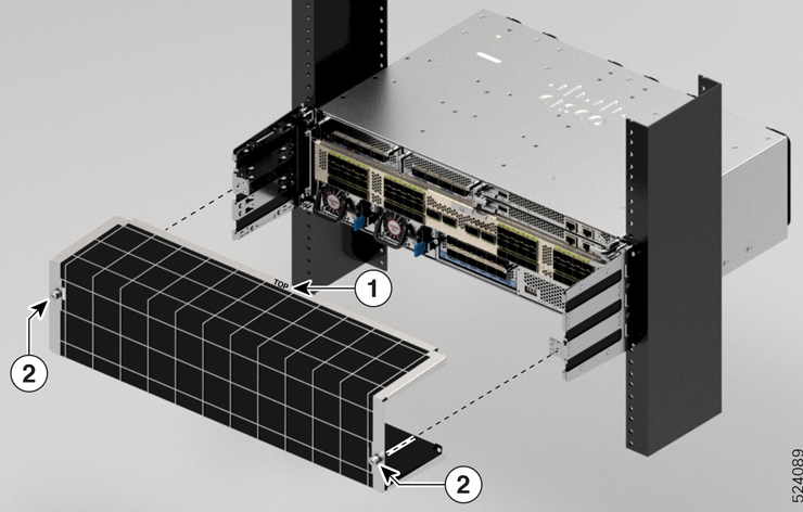
Install the air filter support bracket on either sides of the 19-inch bracket attached to the chassis, using four screws on each side:

  1. Align the holes on the air filter support bracket to the threaded standoffs and guiding pins on the 19-inch bracket.

  2. Insert and tighten four M3 screws to a torque value of 5.75 in-lb (0.65 N.m), to secure the air filter support bracket on each side.

Figure 51. Align and Install the Air Filter Support Bracket
ncs-57c3-router-air-filter-support-bracket

1

Air filter support bracket

3

Threaded standoffs

2

Guiding pins

4

Screws

Step 2

Install the air filter.

  1. Place the air filter as shown in the below figure.

    Figure 52. Install the Air Filter
    ncs-57c3-router-air-filter

    1

    Air filter

    3

    TOP marking on the air filter

    2

    Thumbscrews
  2. Insert and tighten the two thumbscrews to a torque value of 5.75 in-lb (0.65 N.m), to secure the air filter.


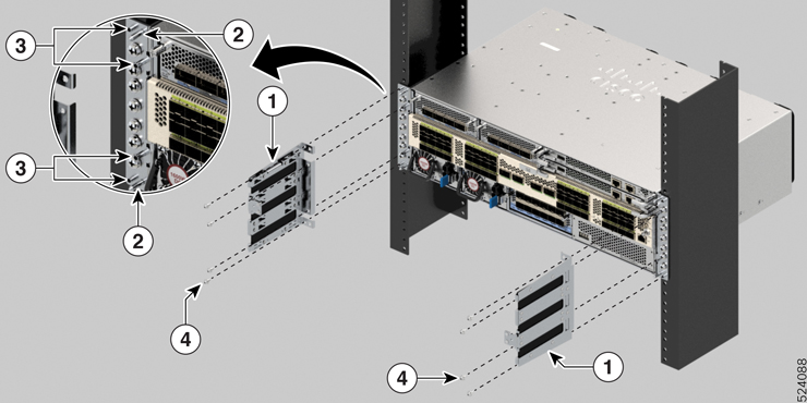
(Optional) Install the Cable Management Bracket on NCS-57C1 Chassis

This section describes how to install the cable management bracket on the NCS-57C1 chassis.

Before you begin

The chassis must be installed and secured to the rack.

Procedure


Step 1

Remove the middle screws from either sides of the chassis. Save the screws for re-installation.

Step 2

Align the cable management bracket with the chassis as shown in the image.

Figure 53. Install Cable Management Bracket on NCS-57C1 Chassis

Step 3

Tighten the 12-24 screws to 30 in-lb (3.39 N.m) on either sides.


Ground the Chassis


Warning


Statement 1024—Ground Conductor

This equipment must be grounded. To reduce the risk of electric shock, never defeat the ground conductor or operate the equipment in the absence of a suitably installed ground conductor. Contact the appropriate electrical inspection authority or an electrician if you are uncertain that suitable grounding is available.


Warning


Statement 1046—Installing or Replacing the Unit

To reduce risk of electric shock, when installing or replacing the unit, the ground connection must always be made first and disconnected last.

If your unit has modules, secure them with the provided screws.


Caution


Grounding the chassis is required, even if the rack is already grounded. A grounding pad with two threaded holes is provided on the chassis for attaching either a grounding lug or grounding cover plate. The ground lug must be NRTL-listed. In addition, a copper conductor (wires) must be used and the copper conductor must comply with NEC code for ampacity.

Caution


When terminating the frame ground, do not use soldering lug connectors, screwless (push-in) connectors, quick connect connectors, or other friction-fit connectors.

Procedure


Step 1

Use a wire-stripping tool to remove approximately 0.75 inches (19 mm) of the covering from the end of the #6 AWG grounding cable.

Step 2

Insert the stripped end of the grounding cable into the open end of the grounding lug.

Step 3

Use the crimping tool to secure the grounding cable in the grounding lug.

In NCS-57D2-18DD-SYS routers, vertical crimping is required to secure the grounding cable.

Step 4

Attach the ground cable:

  1. Remove the adhesive label from the grounding pad on the chassis.

  2. Place the grounding lug against the grounding pad so that there is solid metal-to-metal contact, and insert the provided screws with washers through the holes in the grounding lug and into the grounding pad.

    Figure 54. NCS-57B1-6D24-SYS and NCS-57B1-5DSE-SYS Ground Lug
    Figure 55. NCS-57C1 Ground Lug (Chassis Rear Side)
    Figure 56. NCS-57C3-MOD Ground Lug
    Figure 57. NCS-57D2-18DD-SYS Ground Lug

    1

    Ground lug

    2

    Pan-head screws

    3

    Washer

    4

    Grounding pad

  3. Attach one end of the shelf ground cable (#6 AWG cable) to the grounding cover plate using the specified dual-hole lug connector.

Step 5

Tighten the pan-head screws to torque value of 11.5 in-lbs (1.3 N-m).

Step 6

Ensure that the lug and cable do not interfere with other equipment.

Step 7

Prepare the other end of the grounding cable and connect it to an appropriate grounding point in your site to ensure adequate earth ground.


Connect AC Power to the Chassis


Caution


The chassis relies on the protective devices in the building installation to protect against short circuit, overcurrent, and ground faults. Ensure that the protective devices comply with local and national electrical codes.

Caution


In low-line applications (90-140V AC), redundancy is not guaranteed. Therefore, we recommend to use both AC power supplies.

Note


To obtain full output power of the PSU, the nominal voltage rating value varies, depending on the standards in various countries.


Note


A dual pole breaker is needed for the installation. The rating of the dual pole breaker for 110 V is 20 A and for 220 V is 16 A. The minimum cable size is 14 AWG for 110 V and 16 AWG for 220 V.

Procedure


Step 1

Verify that the AC cable is installed in the correct AC source panel.

Step 2

Attach the AC power cable to the cable connector in the AC power module.

Step 3

Place the cable through the opening in the cable clamp.

Step 4

Slide the cable clamp toward the plug.

Step 5

Close the cable clamp on the shoulder of the power cable to secure the power cable.

Figure 58. Cable Clamp: Examples

1

Cable


Connect DC Power to the Chassis


Warning


Statement 1003—DC Power Disconnection

To reduce risk of electric shock or personal injury, disconnect DC power before removing or replacing components or performing upgrades.


Warning


Statement 1022—Disconnect Device

To reduce the risk of electric shock and fire, a readily accessible disconnect device must be incorporated in the fixed wiring.


Warning


Statement 1046—Installing or Replacing the Unit

To reduce risk of electric shock, when installing or replacing the unit, the ground connection must always be made first and disconnected last.

If your unit has modules, secure them with the provided screws.


Warning


Statement 1074—Comply with Local and National Electrical Codes

To reduce risk of electric shock or fire, installation of the equipment must comply with local and national electrical codes.


Before installing a DC power supply to the switch, you will need to attach DC connection wires that you provide to the DC power connector included in the DC power supply's accessory kit. For 240-380 VDC power supply, the dual-pole breaker or fuse rating is 20 A. For 40-72 VDC power supply, the single breaker or fuse is 40 A.

The following combinations of power supplies are supported on NCS-57B1:

  • PSU2KW-DCPI/PSU2KW-DCPI= , port-side intake airflow

The following combinations of power supplies are supported on NCS-57C1:

  • NCS-950W-DCFW/NCS-950W-DCFW=, port-side intake airflow

  • NCS-1100W-DCRV/NCS-1100W-DCRV=, port-side exhaust airflow

Before you begin

Each DC input power cable is terminated at the power distribution unit (PDU) by a cable lug, as shown in the following figure.
Figure 59. DC Input Power Cable Lug

Note


To avoid hazardous conditions, all components in the area where DC input power is accessible must be properly insulated. Therefore, before installing the DC cable lugs, be sure to insulate the lugs according to the manufacturer's instructions.

Procedure


Step 1

Verify that the correct fuse panel is installed in the top mounting space.

Step 2

Ensure that the DC circuit is powered down (either breaker turned off or fuse pulled) and proper lockout tag out procedures are followed. Use the cable supplied with the power supply. If you prefer to use your own cable, the cable size must be 6 AWG.

Step 3

Dress the power according to local practice.

Step 4

Connect the office battery and return cables according to the fuse panel engineering specifications.

Step 5

(Only NCS-57B1, NCS-57C3, and NCS-57D2) Insert the DC connector into the DC receptacle on the power supply.

  • After connecting to the NCS-57B1 router, the black color (DC positive) wire appears on top.

  • After connecting to the NCS-57C3 router, the red color (DC negative) wire appears on top.

Note

 
To connect the PSU2KW-DCPI power supply module with the power source, you must procure the PWR-2KW-DC-CBL power cord.

Note

 
To connect the NC57-1600W-DCFW power supply module with the power source, you must procure the CAB-48DC-40A-8AWG power cord.

Note

 
To connect the NCS-950W-DCFW power supply module with the power source, use a copper wire that is 14AWG or lesser in size.
Figure 60. NCS-57B1 - Connecting DC Power
Figure 61. NCS-57C3-MOD - Connecting DC Power
Figure 62. NCS-57D2 - Connecting DC Power Cable

1

Cable

Step 6

(Only NCS-57B1, NCS-57C3, and NCS-57D2) Ensure that the locking mechanism has engaged to secure the cable.

Step 7

(Only NCS-57C1) Insert the cables into the connectors and tighten them using the screws as shown in the following figures:

Figure 63. NCS-57C1 - Connecting DC Power Cable

1

Cable

2

Screw

Figure 64. NCS-57C1 - Connecting DC Power Cable

Step 8

Turn on the circuit breaker at the power source.


Power Supply Unit Input and Output Ranges

This table summarises input and output power ranges for PSU low line and nominal applications:

Table 10. Input and output power ranges for PSUs

Routers

Power Supply Unit PIDs

Input Voltage

Input Current (Max)

Output Power

Output

NCS-57B1-6D24-SYS, NCS-57B1-5DSE-SYS, NCS-57D2-18DD-SYS

PSU2KW-ACPI

For low line applications

100 to 127V ac

12A

1000W

12V/84A

NCS-57C3-MOD

NC57-1600W-DCFW

-48V to -60V DC

38A

1600W

12V/133.3A

NCS-57C3-MOD

NC57-1600W-ACFW

100 to 240V AC 20A to 10A (Mainland China, Taiwan)

1600W

12V/133.3A
16A to 10A
NCS-57B1-6D24-SYS, NCS-57B1-5DSE-SYS, NCS-57D2-18DD-SYS

PSU2KW-ACPI

For nominal voltage application

200 to 240V ac

12A

2000W

12V/167A

NCS-57D2-18DD-SYS

PSU2KW-ACPE

100V AC to 127V AC

12A

2000W

12V/167A

NCS-57D2-18DD-SYS

PSU2KW-ACPE

200V AC to 240V AC

10A

2000W

12V/167A

NCS-57B1-6D24-SYS, NCS-57B1-5DSE-SYS, NCS-57D2-18DD-SYS

PSU2KW-DCPI

-40V to -72V DC

40A

2000W

12V/167A

NCS-57B1-6D24-SYS, NCS-57B1-5DSE-SYS, NCS-57D2-18DD-SYS

PSU2KW-DCPE

-48V DC to -60V DC

55A

2000W

12V/167A

NCS-57C1

NCS-1100W-ACFW

For port side intake

For nominal voltage application

100V to 240V ac

12A

1100W

12V/90A

NCS-57C1

NCS-950W-DCFW

For port side intake

For nominal voltage application

-40V to - 72V DC

26A

950W

12V/79A