Implementing BGP

Border Gateway Protocol (BGP) is an Exterior Gateway Protocol (EGP) that allows you to create loop-free interdomain routing between autonomous systems. An autonomous system is a set of routers under a single technical administration. Routers in an autonomous system can use multiple Interior Gateway Protocols (IGPs) to exchange routing information inside the autonomous system and an EGP to route packets outside the autonomous system.

This module provides conceptual and configuration information on BGP.

Release

Modification

Release 6.0

This feature was introduced.

Restrictions for Implementing BGP

  • When paths of different technologies are resolved over ECMP, it results in heterogeneous ECMP, leading to severe network traffic issues. Don’t use ECMP for any combination of the following technologies:

    • LDP.

    • BGP-LU, including services over BGP-LU loopback peering or recursive services at Level-3.

    • VPNv4.

    • 6PE and 6VPE.

    • EVPN.

    • Recursive static routing.

Information about Implementing BGP

To implement BGP, you need to understand the following concepts:

BGP Router Identifier

For BGP sessions between neighbors to be established, BGP must be assigned a router ID. The router ID is sent to BGP peers in the OPEN message when a BGP session is established.

BGP attempts to obtain a router ID in the following ways (in order of preference):

  • By means of the address configured using the bgp router-id command in router configuration mode.

  • By using the highest IPv4 address on a loopback interface in the system if the router is booted with saved loopback address configuration.

  • By using the primary IPv4 address of the first loopback address that gets configured if there are not any in the saved configuration.

If none of these methods for obtaining a router ID succeeds, BGP does not have a router ID and cannot establish any peering sessions with BGP neighbors. In such an instance, an error message is entered in the system log, and the show bgp summary command displays a router ID of 0.0.0.0. After BGP has obtained a router ID, it continues to use it even if a better router ID becomes available. This usage avoids unnecessary flapping for all BGP sessions. However, if the router ID currently in use becomes invalid (because the interface goes down or its configuration is changed), BGP selects a new router ID (using the rules described) and all established peering sessions are reset.


Note


We strongly recommend that the bgp router-id command is configured to prevent unnecessary changes to the router ID (and consequent flapping of BGP sessions).


BGP Route Distinguisher

In network design solutions where customer equipment is dual-homed and Fast Reroute is required, such as in EVPN and BGP PIC Edge solutions, the Route Distinguisher (RD) associated with each VRF must be unique per Provider Edge (PE) router. In other design scenarios, while it isn’t mandatory for the RD to be unique per PE, it is highly recommended to make it unique. This practice facilitates easier transitions to dual-homed solutions in the future.

There are few available options to keep unique RD per device:

  • Manual configuration: You must manually assign a unique value per device in the network. For example, in this scenario:

    • Leaf (ToR) = RD 1

    • Edge DCI Gateway = RD 2

    • Remote PE = RD 3

  • Use rd auto command under VRF. To assign a unique route distinguisher for each router, you must ensure that each router has a unique BGP router-id. If so, the rd auto command assigns a Type 1 route distinguisher to the VRF using the following format: ip-address:number. The IP address is specified by the BGP router-id statement and the number (which is derived as an unused index in the 0 to 65535 range) is unique across the VRFs.


Note


In a DCI deployment, for route re-originate with stitching-rt for a particular VRF, using the same Route Distinguisher (RD) between edge DCI gateway and MPLS-VPN PE or same RD between edge DCI gateway and Leaf (ToR) is not supported.


BGP Default Limits

BGP imposes maximum limits on the number of neighbors that can be configured on the router and on the maximum number of prefixes that are accepted from a peer for a given address family. This limitation safeguards the router from resource depletion caused by misconfiguration, either locally or on the remote neighbor. The following limits apply to BGP configurations:

  • The default maximum number of peers that can be configured is 4000. The default can be changed using the bgp maximum neighbor command. The limit range is 1–15000. Any attempt to configure additional peers beyond the maximum limit or set the maximum limit to a number that is less than the number of peers that are currently configured will fail.

  • To prevent a peer from flooding BGP with advertisements, a limit is placed on the number of prefixes that are accepted from a peer for each supported address family. The default limits can be overridden through configuration of the maximum-prefix limit command for the peer for the appropriate address family. The following default limits are used if the user does not configure the maximum number of prefixes for the address family:
    • 512K (524,288) prefixes for IPv4 unicast

    • 128K (131,072) prefixes for IPv6 unicast

    • 512K (524,288) prefixes for VPNv4 unicast

    A cease notification message is sent to the neighbor and the peering with the neighbor is terminated when the number of prefixes that are received from the peer for a given address family exceeds the maximum limit (either set by default or configured by the user) for that address family.

    It is possible that the maximum number of prefixes for a neighbor for a given address family has been configured after the peering with the neighbor has been established and some prefixes have already been received from the neighbor for that address family. A cease notification message is sent to the neighbor and peering with the neighbor is terminated immediately after the configuration if the configured maximum number of prefixes is fewer than the number of prefixes that have already been received from the neighbor for the address family.

BGP Attributes and Operators

This table summarizes the BGP attributes and operators per attach points.

Table 1. BGP Attributes and Operators

Attach Point

Attribute

Match

Set

aggregation

as-path

in

is-local

length

neighbor-is

originates-from

passes-through

unique-length

as-path-length

is, ge, le, eq

as-path-unique-length

is, ge, le, eq

community

is-empty

matches-any

matches-every

set

set additive

delete in

delete not in

delete all

destination

in

extcommunity cost

set

set additive

local-preference

is, ge, le, eq

set

med

is, eg, ge, le

setset +set -

next-hop

in

set

origin

is

set

source

in

suppress-route

suppress-route

weight

set

allocate-label

as-path

in

is-local

length

neighbor-is

originates-from

passes-through

unique-length

as-path-length

is, ge, le, eq

as-path-unique-length

is, ge, le, eq

community

is-empty

matches-any

matches-every

destination

in

label

set

local-preference

is, ge, le, eq

med

is, eg, ge, le

next-hop

in

origin

is

source

in

clear-policy

as-path

in

is-local

length

neighbor-is

originates-from

passes-through

unique-length

as-path-length

is, ge, le, eq

as-path-unique-length

is, ge, le, eq

dampening

as-path

in

is-local

length

neighbor-is

originates-from

passes-through

unique-length

as-path-length

is, ge, le, eq

as-path-unique-length

is, ge, le, eq

community

is-empty

matches-any

matches-every

dampening

—/

set dampening

destination

in

local-preference

is, ge, le, eq

med

is, eg, ge, le

next-hop

in

origin

is

source

in

debug

destination

in

default originate

med

set

set +

set -

rib-has-route

in

neighbor-in

as-path

in

is-local

length

NA

neighbor-is

originates-from

passes-through

unique-length

prepend

prepend most-recent

remove as-path private-as

replace

as-path-length

is, ge, le, eq

as-path-unique-length

is, ge, le, eq

communitycommunity with ‘peeras’

is-empty

matches-any

matches-every

set

set additive

delete-in

delete-not-in

delete-all

destination

in

extcommunity cost

set

set additive

extcommunity rt

is-empty

matches-any

matches-every

matches-within

set

additive

delete-in

delete-not-in

delete-all

extcommunity soo

is-empty

matches-any

matches-every

matches-within

local-preference

is, ge, le, eq

set

med

is, eg, ge, le

set

set +

set -

next-hop

in

set

set peer address

origin

is

set

route-aggregated

route-aggregated

NA

source

in

weight

set

neighbor-out

as-path

in

is-local

length

neighbor-is

originates-from

passes-through

unique-length

prepend

prepend most-recent

remove as-path private-as

replace

as-path-length

is, ge, le, eq

as-path-unique-length

is, ge, le, eq

communitycommunity with ‘peeras’

is-empty

matches-any

matches-every

set

set additive

delete-in

delete-not-in

delete-all

destination

in

extcommunity cost

set

set additive

extcommunity rt

is-empty

matches-any

matches-every

matches-within

set

additive

delete-in

delete-not-in

delete-all

extcommunity soo

is-empty

matches-any

matches-every

matches-within

local-preference

is, ge, le, eq

set

med

is, eg, ge, le

set

set +

set -

set max-unreachable

set igp-cost

next-hop

in

set

set self

origin

is

set

path-type

is

rd

in

route-aggregated

route-aggregated

source

in

unsuppress-route

unsuppress-route

vpn-distinguisher

set

neighbor-orf

orf-prefix

in

n/a

network

as-path

prepend

community

set

set additive

delete-in

delete-not-in

delete-all

destination

in

extcommunity cost

set

set additive

mpls-label

route-has-label

local-preference

set

med

set

set+

set-

next-hop

in

set

origin

set

route-type

is

tag

is, ge, le, eq

weight

set

next-hop

destination

in

protocol

is,in

source

in

redistribute

as-path

prepend

community

set

set additive

delete in

delete not in

delete all

destination

in

extcommunity cost

setset additive

local-preference

set

med

set

set+

set-

next-hop

in

set

origin

set

mpls-label

route-has-label

route-type

is

tag

is, eq, ge, le

weight

set

retain-rt

extcommunity rt

is-empty

matches-any

matches-every

matches-within

show

as-path

in

is-local

length

neighbor-is

originates-from

passes-through

unique-length

as-path-length

is, ge, le, eq

as-path-unique-length

is, ge, le, eq

community

is-empty

matches-any

matches-every

destination

in

extcommunity rt

is-empty

matches-any

matches-every

matches-within

extcommunity soo

is-empty

matches-any

matches-every

matches-within

med

is, eg, ge, le

next-hop

in

origin

is

source

in

Some BGP route attributes are inaccessible from some BGP attach points for various reasons. For example, the set med igp-cost only command makes sense when there is a configured igp-cost to provide a source value.

This table summarizes which operations are valid and where they are valid.

Table 2. Restricted BGP Operations by Attach Point

Command

import

export

aggregation

redistribution

prepend as-path most-recent

eBGP only

eBGP only

n/a

n/a

replace as-path

eBGP only

eBGP only

n/a

n/a

set med igp-cost

forbidden

eBGP only

forbidden

forbidden

set weight

n/a

forbidden

n/a

n/a

suppress

forbidden

forbidden

n/a

forbidden

BGP Best Path Algorithm

BGP routers typically receive multiple paths to the same destination. The BGP best-path algorithm determines the best path to install in the IP routing table and to use for forwarding traffic. This section describes the Cisco IOS XR software implementation of BGP best-path algorithm, as specified in Section 9.1 of the Internet Engineering Task Force (IETF) Network Working Group draft-ietf-idr-bgp4-24.txt document.

The BGP best-path algorithm implementation is in three parts:

  • Part 1—Compares two paths to determine which is better.

  • Part 2—Iterates over all paths and determines which order to compare the paths to select the overall best path.

  • Part 3—Determines whether the old and new best paths differ enough so that the new best path should be used.


Note


The order of comparison determined by Part 2 is important because the comparison operation is not transitive; that is, if three paths, A, B, and C exist, such that when A and B are compared, A is better, and when B and C are compared, B is better, it is not necessarily the case that when A and C are compared, A is better. This nontransitivity arises because the multi exit discriminator (MED) is compared only among paths from the same neighboring autonomous system (AS) and not among all paths.


Comparing Pairs of Paths

Perform the following steps to compare two paths and determine the better path:

  1. If either path is invalid (for example, a path has the maximum possible MED value or it has an unreachable next hop), then the other path is chosen (provided that the path is valid).

  2. If the paths have unequal pre-bestpath cost communities, the path with the lower pre-bestpath cost community is selected as the best path.

  3. If the paths have unequal weights, the path with the highest weight is chosen.

    Note


    The weight is entirely local to the router, and can be set with the weight command or using a routing policy.


  4. If the paths have unequal local preferences, the path with the higher local preference is chosen.


    Note


    If a local preference attribute was received with the path or was set by a routing policy, then that value is used in this comparison. Otherwise, the default local preference value of 100 is used. The default value can be changed using the bgp default local-preference command.


  5. If one of the paths is a redistributed path, which results from a redistribute or network command, then it is chosen. Otherwise, if one of the paths is a locally generated aggregate, which results from an aggregate-address command, it is chosen.


    Note


    Step 1 through Step 4 implement the “Path Selection with BGP”of RFC 1268.


  6. If the paths have unequal AS path lengths, the path with the shorter AS path is chosen. This step is skipped if bgp bestpath as-path ignore command is configured.


    Note


    When calculating the length of the AS path, confederation segments are ignored, and AS sets count as 1.


    Note


    eiBGP specifies internal and external BGP multipath peers. eiBGP allows simultaneous use of internal and external paths.


  7. If the paths have different origins, the path with the lower origin is selected. Interior Gateway Protocol (IGP) is considered lower than EGP, which is considered lower than INCOMPLETE.

  8. If appropriate, the MED of the paths is compared. If they are unequal, the path with the lower MED is chosen.

    A number of configuration options exist that affect whether or not this step is performed. In general, the MED is compared if both paths were received from neighbors in the same AS; otherwise the MED comparison is skipped. However, this behavior is modified by certain configuration options, and there are also some corner cases to consider.

    If the bgp bestpath med always command is configured, then the MED comparison is always performed, regardless of neighbor AS in the paths. Otherwise, MED comparison depends on the AS paths of the two paths being compared, as follows:

    • If a path has no AS path or the AS path starts with an AS_SET, then the path is considered to be internal, and the MED is compared with other internal paths.

    • If the AS path starts with an AS_SEQUENCE, then the neighbor AS is the first AS number in the sequence, and the MED is compared with other paths that have the same neighbor AS.

    • If the AS path contains only confederation segments or starts with confederation segments followed by an AS_SET, then the MED is not compared with any other path unless the bgp bestpath med confed command is configured. In that case, the path is considered internal and the MED is compared with other internal paths.

    • If the AS path starts with confederation segments followed by an AS_SEQUENCE, then the neighbor AS is the first AS number in the AS_SEQUENCE, and the MED is compared with other paths that have the same neighbor AS.


    Note


    If no MED attribute was received with the path, then the MED is considered to be 0 unless the bgp bestpath med missing-as-worst command is configured. In that case, if no MED attribute was received, the MED is considered to be the highest possible value.


  9. If one path is received from an external peer and the other is received from an internal (or confederation) peer, the path from the external peer is chosen.

  10. If the paths have different IGP metrics to their next hops, the path with the lower IGP metric is chosen.

  11. If the paths have unequal IP cost communities, the path with the lower IP cost community is selected as the best path.

  12. If all path parameters in Step 1 through Step 10 are the same, then the router IDs are compared. If the path was received with an originator attribute, then that is used as the router ID to compare; otherwise, the router ID of the neighbor from which the path was received is used. If the paths have different router IDs, the path with the lower router ID is chosen.


    Note


    Where the originator is used as the router ID, it is possible to have two paths with the same router ID. It is also possible to have two BGP sessions with the same peer router, and therefore receive two paths with the same router ID.


  13. If the paths have different cluster lengths, the path with the shorter cluster length is selected. If a path was not received with a cluster list attribute, it is considered to have a cluster length of 0.

  14. Finally, the path received from the neighbor with the lower IP address is chosen. Locally generated paths (for example, redistributed paths) are considered to have a neighbor IP address of 0.

Order of Comparisons

The second part of the BGP best-path algorithm implementation determines the order in which the paths should be compared. The order of comparison is determined as follows:

  1. The paths are partitioned into groups such that within each group the MED can be compared among all paths. The same rules as in are used to determine whether MED can be compared between any two paths. Normally, this comparison results in one group for each neighbor AS. If the bgp bestpath med always command is configured, then there is just one group containing all the paths.

  2. The best path in each group is determined. Determining the best path is achieved by iterating through all paths in the group and keeping track of the best one seen so far. Each path is compared with the best-so-far, and if it is better, it becomes the new best-so-far and is compared with the next path in the group.

  3. A set of paths is formed containing the best path selected from each group in Step 2. The overall best path is selected from this set of paths, by iterating through them as in Step 2.

Best Path Change Suppression

The third part of the implementation is to determine whether the best-path change can be suppressed or not—whether the new best path should be used, or continue using the existing best path. The existing best path can continue to be used if the new one is identical to the point at which the best-path selection algorithm becomes arbitrary (if the router-id is the same). Continuing to use the existing best path can avoid churn in the network.


Note


This suppression behavior does not comply with the IETF Networking Working Group draft-ietf-idr-bgp4-24.txt document, but is specified in the IETF Networking Working Group draft-ietf-idr-avoid-transition-00.txt document.


The suppression behavior can be turned off by configuring the bgp bestpath compare-routerid command. If this command is configured, the new best path is always preferred to the existing one.

Otherwise, the following steps are used to determine whether the best-path change can be suppressed:

  1. If the existing best path is no longer valid, the change cannot be suppressed.

  2. If either the existing or new best paths were received from internal (or confederation) peers or were locally generated (for example, by redistribution), then the change cannot be suppressed. That is, suppression is possible only if both paths were received from external peers.

  3. If the paths were received from the same peer (the paths would have the same router-id), the change cannot be suppressed. The router ID is calculated using rules in .

  4. If the paths have different weights, local preferences, origins, or IGP metrics to their next hops, then the change cannot be suppressed. Note that all these values are calculated using the rules in .

  5. If the paths have different-length AS paths and the bgp bestpath as-path ignore command is not configured, then the change cannot be suppressed. Again, the AS path length is calculated using the rules in .

  6. If the MED of the paths can be compared and the MEDs are different, then the change cannot be suppressed. The decision as to whether the MEDs can be compared is exactly the same as the rules in , as is the calculation of the MED value.

  7. If all path parameters in Step 1 through Step 6 do not apply, the change can be suppressed.

BGP Update Generation and Update Groups

The BGP Update Groups feature separates BGP update generation from neighbor configuration. The BGP Update Groups feature introduces an algorithm that dynamically calculates BGP update group membership based on outbound routing policies. This feature does not require any configuration by the network operator. Update group-based message generation occurs automatically and independently.

BGP Update Group

When a change to the configuration occurs, the router automatically recalculates update group memberships and applies the changes.

For the best optimization of BGP update group generation, we recommend that the network operator keeps outbound routing policy the same for neighbors that have similar outbound policies. This feature contains commands for monitoring BGP update groups.

BGP Cost Community Reference

The cost community attribute is applied to internal routes by configuring the set extcommunity cost command in a route policy. The cost community set clause is configured with a cost community ID number (0–255) and cost community number (0–4294967295). The cost community number determines the preference for the path. The path with the lowest cost community number is preferred. Paths that are not specifically configured with the cost community number are assigned a default cost community number of 2147483647 (the midpoint between 0 and 4294967295) and evaluated by the best-path selection process accordingly. When two paths have been configured with the same cost community number, the path selection process prefers the path with the lowest cost community ID. The cost-extended community attribute is propagated to iBGP peers when extended community exchange is enabled.

The following commands include the route-policy keyword, which you can use to apply a route policy that is configured with the cost community set clause:

  • aggregate-address

  • redistribute

  • network

BGP Next Hop Reference

Event notifications from the RIB are classified as critical and noncritical. Notifications for critical and noncritical events are sent in separate batches. BGP is notified when any of the following events occurs:
  • Next hop becomes unreachable

  • Next hop becomes reachable

  • Fully recursed IGP metric to the next hop changes

  • First hop IP address or first hop interface change

  • Next hop becomes connected

  • Next hop becomes unconnected

  • Next hop becomes a local address

  • Next hop becomes a nonlocal address


Note


Reachability and recursed metric events trigger a best-path recalculation.


However, a noncritical event is sent along with the critical events if the noncritical event is pending and there is a request to read the critical events.
  • Critical events are related to the reachability (reachable and unreachable), connectivity (connected and unconnected), and locality (local and nonlocal) of the next hops. Notifications for these events are not delayed.

  • Noncritical events include only the IGP metric changes. These events are sent at an interval of 3 seconds. A metric change event is batched and sent 3 seconds after the last one was sent.

BGP is notified when any of the following events occurs:

  • Next hop becomes unreachable

  • Next hop becomes reachable

  • Fully recursed IGP metric to the next hop changes

  • First hop IP address or first hop interface change

  • Next hop becomes connected

  • Next hop becomes unconnected

  • Next hop becomes a local address

  • Next hop becomes a nonlocal address


Note


Reachability and recursed metric events trigger a best-path recalculation.


The next-hop trigger delay for critical and noncritical events can be configured to specify a minimum batching interval for critical and noncritical events using the nexthop trigger-delay command. The trigger delay is address family dependent.

The BGP next-hop tracking feature allows you to specify that BGP routes are resolved using only next hops whose routes have the following characteristics:

  • To avoid the aggregate routes, the prefix length must be greater than a specified value.

  • The source protocol must be from a selected list, ensuring that BGP routes are not used to resolve next hops that could lead to oscillation.

This route policy filtering is possible because RIB identifies the source protocol of route that resolved a next hop as well as the mask length associated with the route. The nexthop route-policy command is used to specify the route-policy.

Next Hop as the IPv6 Address of Peering Interface

BGP can carry IPv6 prefixes over an IPv4 session. The next hop for the IPv6 prefixes can be set through a nexthop policy. In the event that the policy is not configured, the nexthops are set as the IPv6 address of the peering interface (IPv6 neighbor interface or IPv6 update source interface, if any one of the interfaces is configured).

If the nexthop policy is not configured and neither the IPv6 neighbor interface nor the IPv6 update source interface is configured, the next hop is the IPv4 mapped IPv6 address.

Scoped IPv4/VPNv4 Table Walk

To determine which address family to process, a next-hop notification is received by first de-referencing the gateway context associated with the next hop, then looking into the gateway context to determine which address families are using the gateway context. The IPv4 unicast and VPNv4 unicast address families share the same gateway context, because they are registered with the IPv4 unicast table in the RIB. As a result, both the global IPv4 unicast table and the VPNv4 table are is processed when an IPv4 unicast next-hop notification is received from the RIB. A mask is maintained in the next hop, indicating if whether the next hop belongs to IPv4 unicast or VPNv4 unicast, or both. This scoped table walk localizes the processing in the appropriate address family table.

Reordered Address Family Processing

The software walks address family tables based on the numeric value of the address family. When a next-hop notification batch is received, the order of address family processing is reordered to the following order:

  • IPv4 tunnel

  • VPNv4 unicast

  • VPNv6 unicast

  • IPv4 labeled unicast

  • IPv4 unicast

  • IPv4 MDT

  • IPv6 unicast

  • IPv6 labeled unicast

  • IPv4 tunnel

  • VPNv4 unicast

  • IPv4 unicast

  • IPv6 unicast

New Thread for Next-Hop Processing

The critical-event thread in the spkr process handles only next-hop, Bidirectional Forwarding Detection (BFD), and fast-external-failover (FEF) notifications. This critical-event thread ensures that BGP convergence is not adversely impacted by other events that may take a significant amount of time.

show, clear, and debug Commands

The show bgp nexthops command provides statistical information about next-hop notifications, the amount of time spent in processing those notifications, and details about each next hop registered with the RIB. The clear bgp nexthop performance-statistics command ensures that the cumulative statistics associated with the processing part of the next-hop show command can be cleared to help in monitoring. The clear bgp nexthop registration command performs an asynchronous registration of the next hop with the RIB.

The debug bgp nexthop command displays information on next-hop processing. The out keyword provides debug information only about BGP registration of next hops with RIB. The in keyword displays debug information about next-hop notifications received from RIB. The out keyword displays debug information about next-hop notifications sent to the RIB.

BGP Nonstop Routing Reference

BGP NSR provides nonstop routing during the following events:

  • Route processor switchover

  • Process crash or process failure of BGP or TCP

    Note


    BGP NSR is enabled by default. Use the nsr disable command to turn off BGP NSR. The no nsr disable command can also be used to turn BGP NSR back on if it has been disabled.

    In case of process crash or process failure, NSR will be maintained only if nsr process-failures switchover command is configured. In the event of process failures of active instances, the nsr process-failures switchover configures failover as a recovery action and switches over to a standby route processor (RP) or a standby distributed route processor (DRP) thereby maintaining NSR. An example of the configuration command is RP/0/RSP0/CPU0:router(config) # nsr process-failures switchover

    The nsr process-failures switchover command maintains both the NSR and BGP sessions in the event of a BGP or TCP process crash. Without this configuration, BGP neighbor sessions flap in case of a BGP or TCP process crash. This configuration does not help if the BGP or TCP process is restarted in which case the BGP neighbors are expected to flap.

    When the l2vpn_mgr process is restarted, the NSR client (te-control) flaps between the Ready and Not Ready state. This is the expected behavior and there is no traffic loss.


During route processor switchover and In-Service System Upgrade (ISSU), NSR is achieved by stateful switchover (SSO) of both TCP and BGP.

NSR does not force any software upgrades on other routers in the network, and peer routers are not required to support NSR.

When a route processor switchover occurs due to a fault, the TCP connections and the BGP sessions are migrated transparently to the standby route processor, and the standby route processor becomes active. The existing protocol state is maintained on the standby route processor when it becomes active, and the protocol state does not need to be refreshed by peers.

Events such as soft reconfiguration and policy modifications can trigger the BGP internal state to change. To ensure state consistency between active and standby BGP processes during such events, the concept of post-it is introduced that act as synchronization points.

BGP NSR provides the following features:

  • NSR-related alarms and notifications

  • Configured and operational NSR states are tracked separately

  • NSR statistics collection

  • NSR statistics display using show commands

  • XML schema support

  • Auditing mechanisms to verify state synchronization between active and standby instances

  • CLI commands to enable and disable NSR

BGP Route Reflectors Reference

#concept_305B2C3244D5404F9E6207098D05CA9E__ illustrates a simple iBGP configuration with three iBGP speakers (routers A, B, and C). Without route reflectors, when Router A receives a route from an external neighbor, it must advertise it to both routers B and C. Routers B and C do not readvertise the iBGP learned route to other iBGP speakers because the routers do not pass on routes learned from internal neighbors to other internal neighbors, thus preventing a routing information loop.

With route reflectors, all iBGP speakers need not be fully meshed because there is a method to pass learned routes to neighbors. In this model, an iBGP peer is configured to be a route reflector responsible for passing iBGP learned routes to a set of iBGP neighbors. In #concept_305B2C3244D5404F9E6207098D05CA9E__ , Router B is configured as a route reflector. When the route reflector receives routes advertised from Router A, it advertises them to Router C, and vice versa. This scheme eliminates the need for the iBGP session between routers A and C.

The internal peers of the route reflector are divided into two groups: client peers and all other routers in the autonomous system (nonclient peers). A route reflector reflects routes between these two groups. The route reflector and its client peers form a cluster. The nonclient peers must be fully meshed with each other, but the client peers need not be fully meshed. The clients in the cluster do not communicate with iBGP speakers outside their cluster.

#concept_305B2C3244D5404F9E6207098D05CA9E__ illustrates a more complex route reflector scheme. Router A is the route reflector in a cluster with routers B, C, and D. Routers E, F, and G are fully meshed, nonclient routers.

When the route reflector receives an advertised route, depending on the neighbor, it takes the following actions:

  • A route from an external BGP speaker is advertised to all clients and nonclient peers.

  • A route from a nonclient peer is advertised to all clients.

  • A route from a client is advertised to all clients and nonclient peers. Hence, the clients need not be fully meshed.

Along with route reflector-aware BGP speakers, it is possible to have BGP speakers that do not understand the concept of route reflectors. They can be members of either client or nonclient groups, allowing an easy and gradual migration from the old BGP model to the route reflector model. Initially, you could create a single cluster with a route reflector and a few clients. All other iBGP speakers could be nonclient peers to the route reflector and then more clusters could be created gradually.

An autonomous system can have multiple route reflectors. A route reflector treats other route reflectors just like other iBGP speakers. A route reflector can be configured to have other route reflectors in a client group or nonclient group. In a simple configuration, the backbone could be divided into many clusters. Each route reflector would be configured with other route reflectors as nonclient peers (thus, all route reflectors are fully meshed). The clients are configured to maintain iBGP sessions with only the route reflector in their cluster.

Usually, a cluster of clients has a single route reflector. In that case, the cluster is identified by the router ID of the route reflector. To increase redundancy and avoid a single point of failure, a cluster might have more than one route reflector. In this case, all route reflectors in the cluster must be configured with the cluster ID so that a route reflector can recognize updates from route reflectors in the same cluster. All route reflectors serving a cluster should be fully meshed and all of them should have identical sets of client and nonclient peers.

By default, the clients of a route reflector are not required to be fully meshed and the routes from a client are reflected to other clients. However, if the clients are fully meshed, the route reflector need not reflect routes to clients.

As the iBGP learned routes are reflected, routing information may loop. The route reflector model has the following mechanisms to avoid routing loops:

  • Originator ID is an optional, nontransitive BGP attribute. It is a 4-byte attributed created by a route reflector. The attribute carries the router ID of the originator of the route in the local autonomous system. Therefore, if a misconfiguration causes routing information to come back to the originator, the information is ignored.

  • Cluster-list is an optional, nontransitive BGP attribute. It is a sequence of cluster IDs that the route has passed. When a route reflector reflects a route from its clients to nonclient peers, and vice versa, it appends the local cluster ID to the cluster-list. If the cluster-list is empty, a new cluster-list is created. Using this attribute, a route reflector can identify if routing information is looped back to the same cluster due to misconfiguration. If the local cluster ID is found in the cluster-list, the advertisement is ignored.

BGP Persistence

Table 3. Feature History Table

Feature Name

Release Information

Feature Description

BGP Long-lived Graceful Restart Capability on Cisco Network Convergence System 5700 Series Routers

Release 7.7.1

You can retain BGP route information such as IP address, origin packets, destination packets including BGP session failures both in BGP Routing table and forwarding table. BGP Long-lived graceful restart (LLGR) enables the router to retain or maintain stale routes for a longer period after a BGP session fails. LLGR comes into effect after graceful restart (GR) ends. BGP LLGR is also referred as BGP persistence.

This feature introduces the following command:

From this release onwards this functionality is also supported on Cisco Network Convergence System 5700 Series Routers.

BGP persistence enables the local router to retain routes that it has learnt from the configured neighbor even after the neighbor session is down. BGP persistence is also referred as Long Lived Graceful Restart (LLGR). LLGR takes effect after graceful restart (GR) ends or immediately if GR is not enabled. LLGR ends either when the LLGR stale timer expires or when the neighbor sends the end-of-RIB marker after it has revised its routes. When LLGR for a neighbor ends, all routes from that neighbor that are still stale will be deleted. The LLGR capability is signaled to a neighbor in the BGP OPEN message if it has been configured for that neighbor.


Note


You can disable GR helper-only for peer-group and neighbor, when there is no global GR helper-only configured.


LLGR differs from graceful restart in the following ways.

  • It can be in effect for a much longer time than GR.

  • LLGR stale routes are least preferred during route selection (bestpath computation).

  • An LLGR stale route will be advertised with the LLGR_STALE community attached if it is selected as best path. It will not be advertised at all to routers that are not LLGR capable.

  • LLGR stale routes will not be deleted when the forwarding path to the neighbor is detected to be down

  • An LLGR stale route will not be deleted if the BGP session to the neighbor goes down multiple times even if that neighbor does not re-advertise the route.

  • Any route that has the NO_LLGR community will not be retained.

BGP will not pass the updates containing communities 65535:6, 65535:7 to its neighbors until the neighbors negotiate BGP persistence capabilities. The communities 65535:6 and 65535:7 are reserved for LLGR_STALE and NO_LLGR respectively, BGP behavior maybe unpredictable if you have configured these communities prior to release 5.2.2. We recommend not to configure the communities 65535:6 and 65535:7.

The BGP persistence feature is supported only on the following AFIs:

  • VPNv4 and VPNv6

  • RT constraint

  • Flow spec (IPv4, IPv6, VPNv4 and VPNv6)

  • Private IPv4 and IPv6 (IPv4/v6 address family inside VRF)

BGP Persistence Configuration: Example

This example sets long lived graceful restart (LLGR) stale-time of 16777215 on BGP neighbor 10.3.3.3.

router bgp 100
 neighbor 10.3.3.3
  remote-as 30813
  update-source Loopback0
  graceful-restart stalepath-time 150
  address-family vpnv4 unicast
   long-lived-graceful-restart capable
   long-lived-graceful-restart stale-time send 16777215 accept 16777215
  !
  address-family vpnv6 unicast
   long-lived-graceful-restart capable
   long-lived-graceful-restart stale-time send 16777215 accept 16777215

iBGP Multipath Load Sharing Reference

When there are multiple border BGP routers having reachability information heard over eBGP, if no local policy is applied, the border routers will choose their eBGP paths as best. They advertise that bestpath inside the ISP network. For a core router, there can be multiple paths to the same destination, but it will select only one path as best and use that path for forwarding. iBGP multipath load sharing adds the ability to enable load sharing among multiple equi-distant paths. Configuring multiple iBGP best paths enables a router to evenly share the traffic destined for a particular site. The iBGP Multipath Load Sharing feature functions similarly in a Multiprotocol Label Switching (MPLS) Virtual Private Network (VPN) with a service provider backbone.

For multiple paths to the same destination to be considered as multipaths, the following criteria must be met:

  • All attributes must be the same. The attributes include weight, local preference, autonomous system path (entire attribute and not just length), origin code, Multi Exit Discriminator (MED), and Interior Gateway Protocol (iGP) distance.

  • The next hop router for each multipath must be different.

Even if the criteria are met and multiple paths are considered multipaths, the BGP speaking router designates one of the multipaths as the best path and advertises this best path to its neighbors.

Note


  • Overwriting of next-hop calculation for multipath prefixes is not allowed. The next-hop-unchanged multipath command disables overwriting of next-hop calculation for multipath prefixes.

  • The ability to ignore as-path onwards while computing multipath is added. The bgp multipath as-path ignore onwards command ignores as-path onwards while computing multipath.


L3VPN iBGP PE-CE Reference

When BGP is used as the provider edge (PE) or the customer edge (CE) routing protocol, the peering sessions are configured as external peering between the VPN provider autonomous system (AS) and the customer network autonomous system. The L3VPN iBGP PE-CE feature enables the PE and CE devices to exchange Border Gateway Protocol (BGP) routing information by peering as internal Border Gateway Protocol (iBGP) instead of the widely-used external BGP peering between the PE and the CE. This mechanism applies at each PE device where a VRF-based CE is configured as iBGP. This eliminates the need for service providers (SPs) to configure autonomous system override for the CE. With this feature enabled, there is no need to configure the virtual private network (VPN) sites using different autonomous systems.

The neighbor internal-vpn-client command enables PE devices to make an entire VPN cloud act as an internal VPN client to the CE devices. These CE devices are connected internally to the VPN cloud through the iBGP PE-CE connection inside the VRF. After this connection is established, the PE device encapsulates the CE-learned path into an attribute called ATTR_SET and carries it in the iBGP-sourced path throughout the VPN core to the remote PE device. At the remote PE device, this attribute is assigned with individual attributes and the source CE path is extracted and sent to the remote CE devices.

ATTR_SET is an optional transitive attribute that carries the CE path attributes received. The ATTR_SET attribute is encoded inside the BGP update message as follows:

										+------------------------------+
          | Attr Flags (O|T) Code = 128  |
          +------------------------------+
          | Attr. Length (1 or 2 octets) |
          +------------------------------+
          | Origin AS (4 octets)         |
          +------------------------------+
          | Path attributes (variable)   |
          +------------------------------+

Origin AS is the AS of the VPN customer for which the ATTR_SET is generated. The minimum length of ATTR_SET is four bytes and the maximum is the maximum supported for a path attribute after taking into consideration the mandatory fields and attributes in the BGP update message. It is recommended that the maximum length is limited to 3500 bytes. ATTR_SET must not contain the following attributes: MP_REACH, MP_UNREACH, NEW_AS_PATH, NEW_AGGR, NEXT_HOP and ATTR_SET itself (ATTR_SET inside ATTR_SET). If these attributes are found inside the ATTR_SET, the ATTR_SET is considered invalid and the corresponding error handling mechanism is invoked.

Per VRF and Per CE Label for IPv6 Provider Edge

The per VRF and per CE label for IPv6 feature makes it possible to save label space by allocating labels per default VRF or per CE nexthop.

All IPv6 Provider Edge (6PE) labels are allocated per prefix by default. Each prefix that belongs to a VRF instance is advertised with a single label, causing an additional lookup to be performed in the VRF forwarding table to determine the customer edge (CE) next hop for the packet.

However, use the label-allocation-mode command with the per-ce keyword or the per-vrf keyword to avoid the additional lookup on the PE router and conserve label space.

Use per-ce keyword to specify that the same label be used for all the routes advertised from a unique customer edge (CE) peer router. Use the per-vrf keyword to specify that the same label be used for all the routes advertised from a unique VRF.


Note


The label-allocation-mode command is deprecated from 7.4.1 release. The function of this command can be carried out using label mode command under configured address-family.


IPv6 Unicast Routing

Cisco provides complete Internet Protocol Version 6 (IPv6) unicast capability.

An IPv6 unicast address is an identifier for a single interface, on a single node. A packet that is sent to a unicast address is delivered to the interface identified by that address. Cisco IOS XR software supports the following IPv6 unicast address types:

  • Global aggregatable address

  • Site-local address

  • Link-local address

  • IPv4-compatible IPv6 address

For more information on IPv6 unicast addressing, refer the IP Addresses and Services Configuration Guide.

Remove and Replace Private AS Numbers from AS Path in BGP

Private autonomous system numbers (ASNs) are used by Internet Service Providers (ISPs) and customer networks to conserve globally unique AS numbers. Private AS numbers cannot be used to access the global Internet because they are not unique. AS numbers appear in eBGP AS paths in routing updates. Removing private ASNs from the AS path is necessary if you have been using private ASNs and you want to access the global Internet.

Public AS numbers are assigned by InterNIC and are globally unique. They range from 1 to 64511. Private AS numbers are used to conserve globally unique AS numbers, and they range from 64512 to 65535. Private AS numbers cannot be leaked to a global BGP routing table because they are not unique, and BGP best path calculations require unique AS numbers. Therefore, it might be necessary to remove private AS numbers from an AS path before the routes are propagated to a BGP peer.

External BGP (eBGP) requires that globally unique AS numbers be used when routing to the global Internet. Using private AS numbers (which are not unique) would prevent access to the global Internet. The remove and replace private AS Numbers from AS Path in BGP feature allows routers that belong to a private AS to access the global Internet. A network administrator configures the routers to remove private AS numbers from the AS path contained in outgoing update messages and optionally, to replace those numbers with the ASN of the local router, so that the AS Path length remains unchanged.

The ability to remove and replace private AS numbers from the AS Path is implemented in the following ways:

  • The remove-private-as command removes private AS numbers from the AS path even if the path contains both public and private ASNs.

  • The remove-private-as command removes private AS numbers even if the AS path contains only private AS numbers. There is no likelihood of a 0-length AS path because this command can be applied to eBGP peers only, in which case the AS number of the local router is appended to the AS path.

  • The remove-private-as command removes private AS numbers even if the private ASNs appear before the confederation segments in the AS path.

  • The replace-as command replaces the private AS numbers being removed from the path with the local AS number, thereby retaining the same AS path length.

route-policy can be configured either with remove-private-as command or replace-as command, or combination of both.

Following considerations describes the preference of command configurations:

  • When route-policy is not configured, remove-private-as command is considered.

  • When remove-private-as is not configured, replace-private-as command is considered.

  • When remove-private-as and replace-private-as are configured under neighbor's afi-safi command, remove-private-as command is considered.

  • When route-policy is configured with both remove private AS and remove private AS and applied under neighbour afi, replace private AS command is considered.

The feature can be applied to neighbors per address family (address family configuration mode). Therefore, you can apply the feature for a neighbor in one address family and not on another, affecting update messages on the outbound side for only the address family for which the feature is configured.

Use show bgp neighbors and show bgp update-group commands to verify that the that private AS numbers were removed or replaced.

Configure Route Policy

Use the following configuration to configure route policy.

/*Configuration Example*/
Router# configure
Router(config)# route-policy rm_pv_as
Router(config-rpl)# remove as-path private-as entire-aspath
Router(config-rpl)# replace as-path private-as
Router(config-rpl)# commit

Use the following configuration to configure Route Policy with rm-pv-as .

Router# configure
Router(config)# route-policy rm_pv
Router(config-rpl)# replace as-path private-as
Router(config-rpl)# remove as-path private-as entire-aspath
Router(config-rpl# end-policy
Router(config)# router bgp 100
Router(config-bgp)# neighbor 192.168.23.3
Router(config-bgp-nbr)# remote-as 3
Router(config-bgp-nbrgrp)# address-family ipv4 unicast
Router(config-bgp-nbrgrp-af)# route-policy passall in
Router(config-bgp-nbrgrp-af)# route-policy rm_pv out

Use the following configuration to configure Route Policy without rm-pv-as .

Router# configure
Router(config)# route-policy rm_pv
Router(config-rpl)# replace as-path private-as
Router(config-rpl)# remove as-path private-as entire-aspath
Router(config-rpl# end-policy
Router(config)# router bgp 100
Router(config-bgp)# neighbor 192.168.23.3
Router(config-bgp-nbr)# remote-as 3
Router(config-bgp-nbrgrp)# address-family ipv4 unicast
Router(config-bgp-nbrgrp-af)# route-policy passall
Router(config-bgp-nbrgrp-af)# pass
Router(config-bgp-nbrgrp-af)# end-policy
Router(config-bgp)# neighbor 192.168.23.3 
Router(config-bgp-nbr)# remote-as 3
Router(config-bgp-nbr)# address-family ipv4 unicast
Router(config-bgp-nbr-af)# route-policy passall in
Router(config-bgp-nbrgrp-af)# route-policy rm_pv outroute-policy passall out
Router(config-rpl)# replace-private-AS
Router(config-rpl)# remove-private-AS entire-aspath

Running Configuration:

Running configuration of three routers (R1, R2, R3) where the connection topology is: R2--R1--R3

/* Running configuration at R1*/
route-policy rm_pv_as
  replace as-path private-as
  remove as-path private-as entire-aspath
end-policy
!
route-policy passall
  pass
end-policy
!

router bgp 2
 bgp router-id 2.2.2.2
 address-family ipv4 unicast
  redistribute connected
  redistribute static
 !
 address-family vpnv4 unicast
 !
 address-family ipv6 unicast
 !
 address-family vpnv6 unicast
 !
  !
 !
 neighbor 192.168.12.1
  remote-as 64512
  address-family ipv4 unicast
   route-policy passall in
   route-policy passall out
  !
 !
 neighbor 192.168.23.3
  remote-as 3
  address-family ipv4 unicast
   route-policy passall in
   route-policy rm_pv_as out
  !
 !
!
/*Running configuration at R2*/
route-policy passall
  pass
end-policy
!
router bgp 64512
 bgp router-id 1.1.1.1
 address-family ipv4 unicast
  network 10.10.10.10/32
 !
 address-family vpnv4 unicast
 !
 address-family ipv6 unicast
 !
 address-family vpnv6 unicast
 !
 neighbor 192.168.12.2
  remote-as 2
  address-family ipv4 unicast
   route-policy passall in
   route-policy passall out
  !
 !
/*Running configuration at R3*/
router bgp 3
 bgp router-id 3.3.3.3
 address-family ipv4 unicast
 !
 address-family vpnv4 unicast
 !
 address-family ipv6 unicast
 !
 address-family vpnv6 unicast
 !
 neighbor 192.168.23.2
  remote-as 2
  address-family ipv4 unicast
   route-policy passall in
   route-policy passall out
  !
 !
!

Verification

/*validate the configuration */
Router# show bgp
BGP router identifier 3.3.3.3, local AS number 3
BGP generic scan interval 60 secs
Non-stop routing is enabled
BGP table state: Active
Table ID: 0xe0000000   RD version: 6
BGP main routing table version 6
BGP NSR Initial initsync version 6 (Reached)
BGP NSR/ISSU Sync-Group versions 0/0
BGP scan interval 60 secs

Status codes: s suppressed, d damped, h history, * valid, > best
              i - internal, r RIB-failure, S stale, N Nexthop-discard
Origin codes: i - IGP, e - EGP, ? - incomplete
   Network            Next Hop            Metric LocPrf Weight Path
*> 10.10.10.10/32     192.168.23.2                           0 2 2 i
*> 192.168.12.0/24    192.168.23.2             0             0 2 ?
*> 192.168.23.0/24    192.168.23.2             0             0 2 ?
*> 192.168.122.0/24   192.168.23.2             0             0 2 ?

Replace BGP AS Path with Custom Values

Table 4. Feature History Table

Feature Name

Release Information

Feature Description

Replace BGP AS Path with Custom Values

Release 7.5.2

You can now configure route policies to replace the Autonomous System (AS) Path in BGP with custom values to control the best path selection process.

This feature introduces the replace as-path all command.

BGP routers typically receive multiple paths to the same destination. The BGP best-path algorithm determines the best path to install in the IP routing table and to use for forwarding traffic. The overall best path is selected based on various attributes. .

AS path is one of the attributes used for best path selection. By default, BGP always prefers the route with shortest AS path as the best path. The best path selected by BGP might have traffic engineering issues, like heavy traffic that leads to congestion. In such cases, you can alter the best path by replacing the AS path with custom values.

The following are the custom values you can use to replace the AS path:

  • None: Use this option to modify an AS path as the shortest path in the network. When you choose this option, the AS path is replaced with a null or empty value. Use the replace as-path all none command to replace with none.

  • Auto: Use this option to advertise the local AS number or the neigbor's AS number as the AS path. When you choose this option, AS path is replaced based on the route policy:

    • For inbound route policy, AS path is replaced with AS path of BGP neighbor from where the prefix is received.

    • For outbound route policy, AS path is replaced with the local AS number.

    Use the replace as-path all auto command to replace with auto.

  • 'x': Use this option to replace AS path with any specified value. Use the replace as-path all 'x' command to replace with this option, where 'x' can be a single AS number or a sequence of AS numbers separated by space.

  • Optionally, you can repeat replacing the AS path for a specified number of times. This option is supported only for the auto and 'x' parameters. Use the replace as-path all {auto | 'x'} [n] command to enable the repeat option.

  • Optionally, you can use a parameter name along with the repeat option. The parameter name must be preceded with a “$.” You can attach the route policy with the parameter to a neighbor and specify the number of times the AS path replacement should be repeated. This opton allows you to apply the same route policy to different neighbors with different AS path values.

    Use the replace as-path all {auto | 'x'} [n] [parameter] command to enable the parameter along with repeat option.

You can replace the AS path for inbound eBGP, outbound eBGP, and outbound iBGP paths.


Note


For outbound eBGP paths, the AS number of the local router is always prepended to the replaced AS path.


Interoperability with BGP Confederation

BGP confederation is a group of multiple autonomous systems that looks like a single autonomous system to the outside world. When confederation is configured on BGP peers, the AS path is replaced as follows:

  • When you replace the AS path in an outbound BGP router, which receives prefix from a BGP neighbor configured with confederation, the specified AS path value is appended to the confederation sequence.

  • When you replace the AS path in an inbound BGP router configured with confederation, the confederation sequence is replaced with the specified AS path value.

Deployment Scenario

Consider a BGP network configured with AS paths. By default, BGP selects the route with shortest AS path to reach the destination. You can alter the default route by using the replace BGP AS path feature.

In the following figure, the network consists of BGP routers configured with AS Path values. To reach Server B, Server A typically selects Path B (via S1_1, S0), as the AS path value of S0 is shorter.

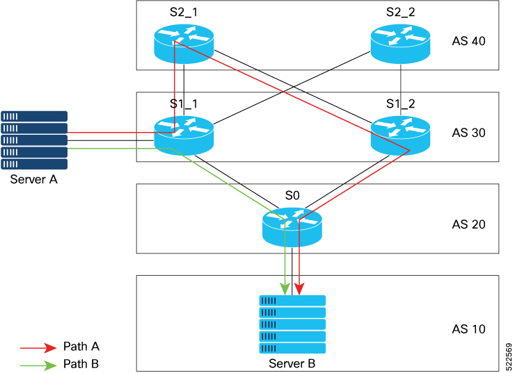
You may want to use Path A to reach the destination (via S1_1, S2_1, S1_2, S0), for traffic engineering purpose. For example, Path A may be less congested and is better than Path B. To use Path A, you can replace the AS path values with one of the following options:

  • Replace AS path of Router S2_1 with a shorter value.

  • Replace AS path of Router S0 with a longer value.

Restrictions

  • The replace as-path all command isn't supported on inbound iBGP paths.

  • The replace as-path all command isn't supported on a route policy that is already configured with remove-private-as or replace as commands.

  • You can apply the route policy configured with replace as-path all only on neighbor-in or neighbor-out attach points.

Configuration Example

To replace BGP AS path with custom values, perform the following tasks on a BGP router:

This example shows how to replace AS path with null value.

/*Configure route policy to replace AS path with none*/
Router(config)#hw-module profile stats ?
Router(config)# route-policy aspath-none
Router(config-rpl)# replace as-path all none
Router(config-rpl)# end-policy

/* Apply route policy to BGP neighbor */
Router(config)# router bgp 65530
Router(config-bgp)# neighbor 111.0.0.1
Router(config-bgp-nbr)# address-family ipv4 unicast
Router(config-bgp-nbr-af)# route-policy aspath-none in

This example shows how to replace AS path with auto option.


/*Configure route policy to replace AS path with auto*/
Router(config)#route-policy aspath-auto
Router(config-rpl)# replace as-path all auto
Router(config-rpl)# end-policy


/* Apply route policy to BGP neighbor */
Router(config)# router bgp 65530
Router(config-bgp)# neighbor 111.0.0.1
Router(config-bgp-nbr)# address-family ipv4 unicast
Router(config-bgp-nbr-af)# route-policy aspath-auto out

This example shows how to replace AS path with a specified sequence of AS numbers. In this example, sequence '10 100 200 300' is used.


/*Configure route policy to replace AS path with 'x'*/
Router(config)# route-policy aspath-str
Router(config-rpl)# replace as-path all '10 100 200 300'
Router(config-rpl)# end-policy


/* Apply route policy to BGP neighbor */
Router(config)# router bgp 1
Router(config-bgp)# neighbor 111.0.0.1
Router(config-bgp-nbr)# address-family ipv4 unicast
Router(config-bgp-nbr-af)# route-policy aspath-str in

This example shows how to use replace as-path all command along with parameter to replace the AS path with specified sequence of values, repeated for specified number of times. In this example, AS path is replaced with sequence '45 55', repeated for 6 times.


/*Configure route policy to replace AS path with parameter ($n)*/
Router(config)# route-policy aspath-par($n)
Router(config-rpl)# replace as-path all '45 55' $n
Router(config-rpl)# end-policy


/* Apply route policy to BGP neighbor */
Router(config)# router bgp 1
Router(config-bgp)# neighbor 111.0.0.1
Router(config-bgp-nbr)# address-family ipv4 unicast
Router(config-bgp-nbr-af)# route-policy aspath-par(6) in

Verification

In the following output, AS path is replaced with null value.


Router# show bgp
Network               Next Hop            Metric LocPrf Weight Path
*> 192.168.3.0/24     192.168.3.1                     0      0    i

In the following output, AS path is replaced with auto for an outbound path, where the AS path of local router is [40].


Router# show bgp
Network            Next Hop            Metric LocPrf Weight Path
*> 111.0.0.2/32    200.0.0.5                       0         40 i    

In the following output, AS path is replaced with the sequence '10 100 200 300'.


Router# show bgp
Network            Next Hop            Metric LocPrf Weight Path
*>111.0.0.2/32      200.0.0.5                      0 10 100 200 300 i

In the following output, AS path is replaced with the sequence '45 55', repeated for 6 times.


Router# show bgp
Network            Next Hop            Metric LocPrf Weight Path
*>111.0.0.8/32      200.0.0.5                      0        45 55 45 55 45 55 45 55 45 55 45 55 i

BGP Update Message Error Handling

The BGP UPDATE message error handling changes BGP behavior in handling error UPDATE messages to avoid session reset. Based on the approach described in IETF IDR I-D:draft-ietf-idr-error-handling, the Cisco IOS XR BGP UPDATE Message Error handling implementation classifies BGP update errors into various categories based on factors such as, severity, likelihood of occurrence of UPDATE errors, or type of attributes. Errors encountered in each category are handled according to the draft. Session reset will be avoided as much as possible during the error handling process. Error handling for some of the categories are controlled by configuration commands to enable or disable the default behavior.

According to the base BGP specification, a BGP speaker that receives an UPDATE message containing a malformed attribute is required to reset the session over which the offending attribute was received. This behavior is undesirable as a session reset would impact not only routes with the offending attribute, but also other valid routes exchanged over the session.

Discard Incoming BGP Update Message

Table 5. Feature History Table

Feature Name

Release Information

Feature Description

Discard Incoming BGP Update Message

Release 7.10.1

Introduced in this release on: NCS 5500 fixed port routers; NCS 5700 fixed port routers; NCS 5500 modular routers (NCS 5500 line cards; NCS 5700 line cards [Mode: Compatibility; Native])

You can now avoid the session reset when a BGP session encounters errors while parsing the received update message. This is made possible because the feature enables discarding the incoming update message as a withdraw message.

The feature introduces these changes:

CLI

New Command:

YANG Data Model

BGP Error Handling and Attribute Filtering Syslog Messages

When a router receives a malformed update packet, an ios_msg of type ROUTING-BGP-3-MALFORM_UPDATE is printed on the console. This is rate limited to 1 message per minute across all neighbors. For malformed packets that result in actions "Discard Attribute" (A5) or "Local Repair" (A6), the ios_msg is printed only once per neighbor per action. This is irrespective of the number of malformed updates received since the neighbor last reached an "Established" state.

This is a sample BGP error handling syslog message:

%ROUTING-BGP-3-MALFORM_UPDATE : Malformed UPDATE message received from neighbor 13.0.3.50 - message length 90 bytes,
 error flags 0x00000840, action taken "TreatAsWithdraw". 
Error details: "Error 0x00000800, Field "Attr-missing", Attribute 1 (Flags 0x00, Length 0), Data []"

This is a sample BGP attribute filtering syslog message for the "discard attribute" action:

[4843.46]RP/0/0/CPU0:Aug 21 17:06:17.919 : bgp[1037]: %ROUTING-BGP-5-UPDATE_FILTERED : 
One or more attributes were filtered from UPDATE message received from neighbor 40.0.101.1 - message length 173 bytes,
 action taken "DiscardAttr".
 Filtering details: "Attribute 16 (Flags 0xc0): Action "DiscardAttr"". NLRIs: [IPv4 Unicast] 88.2.0.0/17

This is a sample BGP attribute filtering syslog message for the "treat-as-withdraw" action:

[391.01]RP/0/0/CPU0:Aug 20 19:41:29.243 : bgp[1037]: %ROUTING-BGP-5-UPDATE_FILTERED :
 One or more attributes were filtered from UPDATE message received from neighbor 40.0.101.1 - message length 166 bytes,
 action taken "TreatAsWdr".
 Filtering details: "Attribute 4 (Flags 0xc0): Action "TreatAsWdr"". NLRIs: [IPv4 Unicast] 88.2.0.0/17

BGP-RIB Feedback Mechanism for Update Generation

The Border Gateway Protocol-Routing Information Base (BGP-RIB) feedback mechanism for update generation feature avoids premature route advertisements and subsequent packet loss in a network. This mechanism ensures that routes are installed locally, before they are advertised to a neighbor.

BGP waits for feedback from RIB indicating that the routes that BGP installed in RIB are installed in forwarding information base (FIB) before BGP sends out updates to the neighbors. RIB uses the the BCDL feedback mechanism to determine which version of the routes have been consumed by FIB, and updates the BGP with that version. BGP will send out updates of only those routes that have versions up to the version that FIB has installed. This selective update ensures that BGP does not send out premature updates resulting in attracting traffic even before the data plane is programmed after router reload, LC OIR, or flap of a link where an alternate path is made available.

To configure BGP to wait for feedback from RIB indicating that the routes that BGP installed in RIB are installed in FIB, before BGP sends out updates to neighbors, use the update wait-install command in router address-family IPv4 or router address-family VPNv4 configuration mode. The show bgp , show bgp neighbors , and show bgp process performance-statistics commands display the information from update wait-install configuration.

Delay BGP Route Advertisements

Table 6. Feature History Table

Feature Name

Release Information

Feature Description

Delay BGP Route Advertisements

Release 7.5.3

You can now prevent traffic loss due to premature advertising of BGP routes and subsequent packet loss in a network. You can achieve this by setting the delay time of the BGP start-up in the router until the Routing Information Base (RIB) is synchronized with the Forward Information Base (FIB) in the routing table. This delays the BGP update generation and prevents traffic loss in a network.

You can configure a minimum delay of 1 second and a maximum delay of 600 seconds.

This feature introduces the update wait-install delay startup command.

When BGP forwards traffic, it waits for feedback from the RIB until the RIB is ready to forward traffic. Once the RIB is ready, BGP sends the route updates to the BGP neighbors and peer-groups. Advertising routes before the RIB is synchronized in the FIB results in traffic loss. To avoid this problem, the router must delay the BGP start-up process to delay the BGP update generation so that no traffic loss happens.

To accomplish this, you must configure the update wait-install delay startup command to delay the generation of BGP updates. The show bgp process command displays the delay of the BGP process update since the last router reload.

This feature allows you to configure the minimum and maximum delay periods. The range of the delay is from 1 second to 600 seconds. As a result, network traffic loss is avoided.

Restrictions

This feature is applicable for the following Address Family Indicators (AFIs):

  • IPv4 unicast

  • IPv6 unicast

  • VPNv4 unicast

  • VPNv6 unicast

Configuration

  1. Enter the IOS XR configuration mode.

    Router# configure
  2. Specify the BGP Autonomous System Number (AS Number).

    Router(config)# router bgp 1
  3. Specify the IP address from the address-family (Pv4, IPv6, VPNv4, or VPNv6) options.

    Router(config-bgp)# address-family {ipv4| ipv6| vpnv4| vpn6} unicast
    For example,
    Router(config-bgp)# address-family ipv4 unicast
  4. Schedule the delay of the BGP process to prevent routes from being advertised to peers until RIB is synchronized.

    Router(config-bgp-af)# update wait-install delay startup (time in seconds) 
    For example,
    Router(config-bgp-af)# update wait-install delay startup 10
  5. Commit the changes.

    Router(config-bgp-af)#commit

Note


The delay time ranges from 1 second to 600 seconds.


Running Configuration

configure
router bgp 1
 address-family ipv4 unicast
  update wait-install delay startup 10
!

Verification Example

The following command displays the delay of the BGP process update:

Router# show running-config router bgp 1
router bgp 1
address-family ipv4 unicast
update wait-install delay startup 10


Use-defined Martian Check

The solution allows disabling the Martian check for these IP address prefixes:

  • IPv4 address prefixes

    • 0.0.0.0/8

    • 127.0.0.0/8

    • 224.0.0.0/4

  • IPv6 address prefixes

    • ::

    • ::0002 - ::ffff

    • ::ffff:a.b.c.d

    • fe80:xxxx

    • ffxx:xxxx

BGP DMZ Aggregate Bandwidth

Table 7. Feature History Table

Feature Name

Release Information

Feature Description

Removal of Link-Bandwidth Extended Community to iBGP Peers

Release 7.3.2

The demilitarized zone (DMZ) link-bandwidth extended community allows BGP to send traffic over multiple internal BGP (iBGP) learned paths. The traffic that is sent is proportional to the bandwidth of the links that are used to exit the autonomous system. By default, iBGP propagates DMZ link-bandwidth community. The Removal of Link-Bandwidth Extended Community to iBGP Peers feature provides the flexibility to remove the DMZ link-bandwidth community to minimize the risk of exposure of the community parameters to networks zones where they are not recognized or unnecessary.

BGP supports aggregating dmz-link bandwidth values of external BGP (eBGP) multipaths when advertising the route to interior BGP (iBGP) peer.

There is no explicit command to aggregate bandwidth. The bandwidth is aggregated if following conditions are met:

  • The network has multipaths and all the multipaths have link-bandwidth values.

  • The next-hop attribute set to next-hop-self. The next-hop attribute for all routes advertised to the specified neighbor to the address of the local router.

  • There is no out-bound policy configured that might change the dmz-link bandwidth value.

  • If the dmz-link bandwidth value is not known for any one of the multipaths (eBGP or iBGP), the dmz-link value for all multipaths including the best path is not downloaded to routing information base (RIB).

  • The dmz-link bandwidth value of iBGP multipath is not considered during aggregation.

  • The route that is advertised with aggregate value can be best path or add-path.

  • Add-path does not qualify for DMZ link bandwidth aggregation as next hop is preserved. Configuring next-hop-self for add-path is not supported.

  • For VPNv4 and VPNv6 afi, if dmz link-bandwidth value is configured using outbound route-policy, specify the route table or use the additive keyword. Else, this will lead to routes not imported on the receiving end of the peer.

extcommunity-set bandwidth dmz_ext
   1:8000
 end-set
 !
 route-policy dmz_rp_vpn
   set extcommunity bandwidth dmz_ext additive     <<< 'additive' keyword.
   pass
 end-policy

Removal of Link-Bandwidth Extended Community to iBGP Peers

The demilitarized zone (DMZ) link-bandwidth extended community allows BGP to send traffic over multiple internal BGP (iBGP) learned paths. The traffic that is sent is proportional to the bandwidth of the links that are used to exit the autonomous system. By default, iBGP propagates DMZ link-bandwidth community. The Removal of Link-Bandwidth Extended Community to iBGP Peers feature provides the flexibility to remove the DMZ link-bandwidth community to minimize the risk of exposure of the community parameters to networks zones where they are not recognized or unnecessary.

Configuration Example

Perform the following steps to allow users to be able to configure route-policy to remove the extended communities.


/* Delete all the extended communities. */
Router(config)# route-policy dmz_del_all 
Router(config-rpl)# delete extcommunity bandwidth all
Router(config-rpl)# pass
Router(config-rpl)# end-policy

/* Delete only the extended communities that match an extended community mentioned in the list. */ 
Router(config)# route-policy dmz_CE1_del_non_match
Router(config-rpl)# if destination in (10.9.9.9/32) then 
Router(config-rpl-if)# delete extcommunity bandwidth in (10:7000)
Router(config-rpl-if)# endif
Router(config-rpl)# pass
Router(config-rpl)# end-policy

/* Delete all the extended communities. */
Router(config)# route-policy dmz_del_param2($a,$b)
Router(config-rpl)# if destination in (10.9.9.9/32) then 
Router(config-rpl-if)# delete extcommunity bandwidth in ($a:$b)
Router(config-rpl-if)# endif
Router(config-rpl)# pass
Router(config-rpl)# end-policy

Verification

Verify the configuration that allows the user to remove a particular extended community.

Router# show bgp 10.9.9.9/32
Fri Aug 27 13:15:05.833 EDT
BGP routing table entry for 10.9.9.9/32
Versions:
Process bRIB/RIB SendTblVer
Speaker 15 15
Last Modified: Aug 27 13:06:45.000 for 00:08:21
Paths: (3 available, best #1)
Advertised IPv4 Unicast paths to peers (in unique update groups):
13.13.13.5
Path #1: Received by speaker 0
Advertised IPv4 Unicast paths to peers (in unique update groups):
13.13.13.5
10
10.10.10.1 from 10.10.10.1 (192.168.0.1)
Origin incomplete, metric 0, localpref 100, valid, external, best, group-best, multipath
Received Path ID 0, Local Path ID 1, version 15
Extended community: LB:10:48
Origin-AS validity: (disabled)
Path #2: Received by speaker 0
Not advertised to any peer
10
11.11.11.3 from 11.11.11.3 (192.168.0.3)
Origin incomplete, metric 0, localpref 100, valid, external, multipath
Received Path ID 0, Local Path ID 0, version 0
Extended community: LB:10:48
Origin-AS validity: (disabled)
Path #3: Received by speaker 0
Not advertised to any peer
10
12.12.12.4 from 12.12.12.4 (192.168.0.4)
Origin incomplete, metric 0, localpref 100, valid, external, multipath
Received Path ID 0, Local Path ID 0, version 0
Extended community: LB:10:48
Origin-AS validity: (disabled)

22:35 30-09-2021

BGP Extended Route Retention

Table 8. Feature History Table

Feature Name

Release Name

Description

BGP Extended Route Retention

Release 7.3.3

This feature allows you to maintain stale routing information from a failed BGP peer for longer periods of time than that is configured in the Graceful Restart atribute. However, this feature ensures that the BGP neighbor considers the stale routes as new routes.

When a BGP peer fails, the BGP Extended Route Rention feature applies the route retention policy to the routes to modify the route attributes. This feature modifies the route attributes in addition to the modification that occur due to neighbor's inbound policy. This feature enables the use of route retention policy in place of LLGR, when the BGP hold timer expires or when the BGP session fails to reestablish as a receiving speaker within the configured graceful retart timer.

When you apply LLGR, you cannot remove the LLGR_STALE community when the stale route is advertised, and the route will treat it as the least preferred. Also, stale routes may be advertised to those neighbors that would not have advertised the LLGR capability under the following confitions:

  • The neighbors must be internal, either IBGP or confederation, neighbors.

  • The NO_EXPORT community must be attached to the stale routes.

  • The stale routes must have their LOCAL_PREF community set to zero.

This feature provides you the flexibility to advertise stale routes to eBGP neighbors and enable you to specify local preference values for any stale route that is retained within the iBGP system.

Restrictions

  • The neighbor should be capable of graceful restart.

  • When the BGP neighbor fails, the graceful retart functionality is applied till the graceful restart timer is valid.

  • The Extend Route Retention feature starts, when the graceful restart timer expires,

  • Soft-reconfiguration inbound configuration is a mandatory configuration. If required, configure the inbound policy.

  • The Extended Route Retention feature starts only when BGP peer goes down, that is, on the expiry of the hold-down timer.

  • For any other trigger, such as the expiry of a timer, the routes are not indicated as stale and the routes are purged.

  • The Extended Route Retention feature is applicable only in the following address-family modes:

    • IPv4 and IPv6 unicast address family mode

    • IPv4 and IPv4 labelled unicast address family mode

  • You cannot configure both LLGR and Extended Route Retention feature on the same neighbor.

  • When you configure the Extended Route Retention feature, the capablity attribute is not sent.

Configuration Example

Configure a route policy:

Router(config)# route-policy RRP_comm_no_export_local_pref_2500
Router(config-rpl)# set community RRP_comm_no_export additive
Router(config-rpl)# set local-preference 2500
Router(config-rpl)# end-policy
Router(config-rpl)# exit
Router(config)# route-policy comm_number_local_pref
Router(config-rpl)# set community comm_number
Router(config-rpl)# set local-preference 10000
Router(config-rpl)# end-policy

Apply route policy parameters to a neighbor:

Router(config)# router bgp 140
Router(config-bgp)# neighbor 10.1.1.1
Router(config-bgp-nbr)# remote-as 1
Router(config-bgp-nbr)# update-source Loopback 0
Router(config-bgp-nbr)# address-family ipv4 unicast
// Configure route-retention policy
Router(config-bgp-nbr-af)# route-policy RRP_comm_no_export_local_pref_2500 retention retention-time 2340  
// Configure the inbound route policy
Router(config-bgp-nbr-af)# route-policy comm_number_local_pref in 
// Enables the view of the peer's adj-rib-in table
Router(config-bgp-nbr-af)# soft-reconfiguration inbound always 

Verification

Verify the configured route-retention policy:

Router# show bgp neighbor 10.1.1.1
Fri Oct 22 04:52:44.972 PDT

BGP neighbor is 10.1.1.1
 Remote AS 1, local AS 1, internal link
 Remote router ID 10.1.1.1
  BGP state = Established, up for 00:03:03
…
 For Address Family: IPv4 Unicast
  BGP neighbor version 16172
Policy for incoming advertisements is comm_number_local_pref
  Policy for Retention is RRP_comm_no_export_local_pref_2500
Configured route retention policy stale timer for routes is 2340 seconds
….

Verify the stale routes.

Router# show bgp ipv4 unicast 181.1.1.0/24
Fri Oct 22 04:56:15.906 PDT
….
Path #1: Received by speaker 0
  Advertised IPv4 Unicast paths to peers (in unique update groups):
    3.3.3.3         
  100, (Received from a RR-client), (long-lived/route-retention policy stale)
    192.1.2.1 (metric 10) from 192.1.2.1 (10.1.1.1)
      Origin IGP, metric 1221, localpref 2500, valid, internal, best, group-best, multipath
      Received Path ID 0, Local Path ID 1, version 16243
      Community: 1:100 no-export
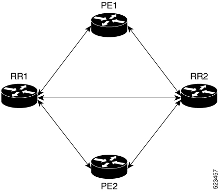
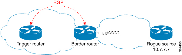
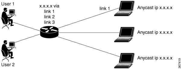
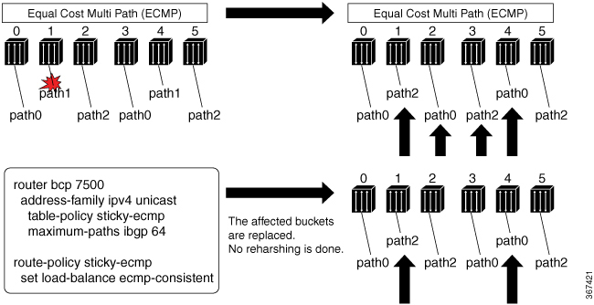
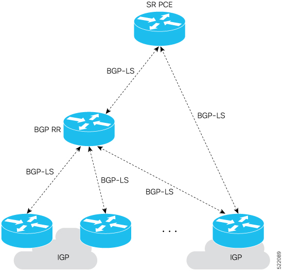
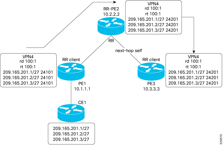
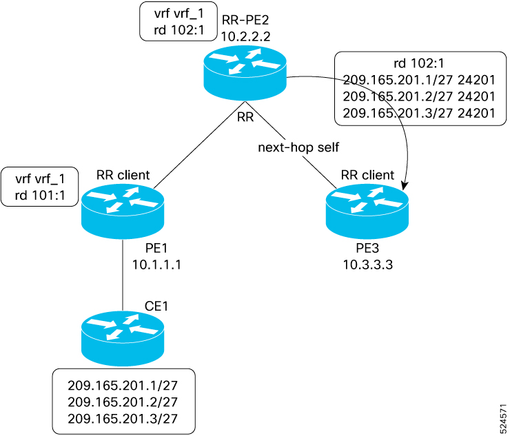
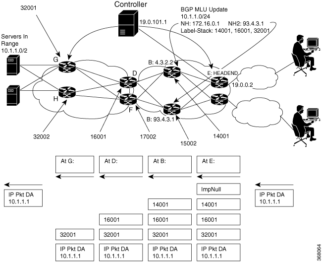
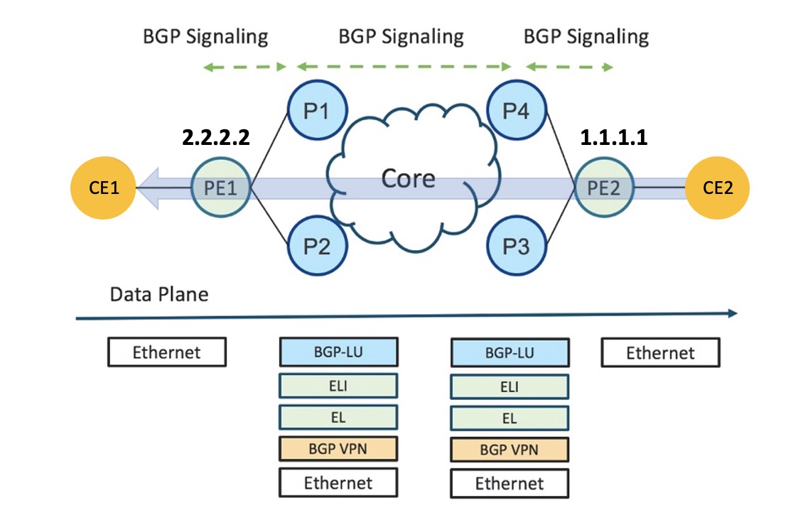
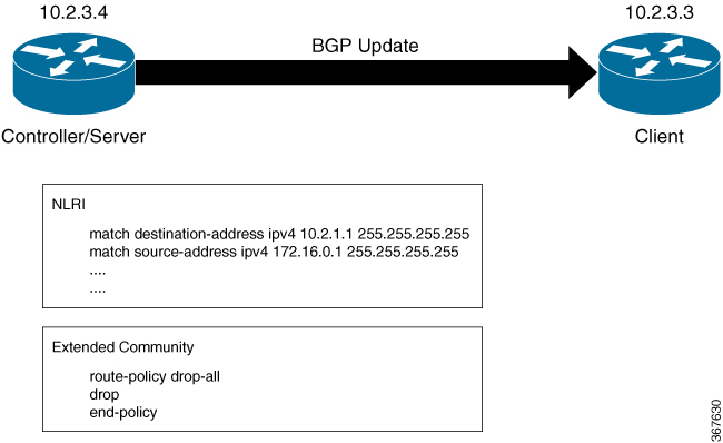
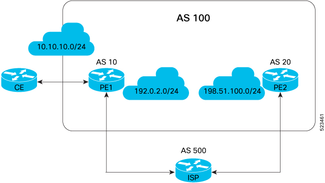
BGP Functional Overview

Table 9. Feature History Table

Feature Name

Release Information

Feature Description

BGP Fallback Feature for LAG Bundles Release 7.5.1

This feature is now supported on routers that have Cisco NC57 line cards installed and operate in native and compatibiltiy mode.

This feature enables you to recreate the essence of OSPF Cost Fallback feature for LAG bundles for directly connected BGP sessions from a PE to a core router.

BGP uses TCP as its transport protocol. Two BGP routers form a TCP connection between one another (peer routers) and exchange messages to open and confirm the connection parameters.

BGP routers exchange network reachability information. This information is mainly an indication of the full paths (BGP autonomous system numbers) that a route should take to reach the destination network. This information helps construct a graph that shows which autonomous systems are loop free and where routing policies can be applied to enforce restrictions on routing behavior.

Any two routers forming a TCP connection to exchange BGP routing information are called peers or neighbors. BGP peers initially exchange their full BGP routing tables. After this exchange, incremental updates are sent as the routing table changes. BGP keeps a version number of the BGP table, which is the same for all of its BGP peers. The version number changes whenever BGP updates the table due to routing information changes. Keepalive packets are sent to ensure that the connection is alive between the BGP peers and notification packets are sent in response to error or special conditions.


Note


VPNv4 address family is supported effective from Cisco IOS XR Release 6.1.31. However, VPNv6 and VPN routing and forwarding (VRF) address families will be supported in a future release.

Enable BGP Routing

Perform this task to enable BGP routing and establish a BGP routing process. Configuring BGP neighbors is included as part of enabling BGP routing.


Note


  • At least one neighbor and at least one address family must be configured to enable BGP routing. At least one neighbor with both a remote AS and an address family must be configured globally using the address family and remote as commands.

  • When one BGP session has both IPv4 unicast and IPv4 labeled-unicast AFI/SAF, then the routing behavior is nondeterministic. Therefore, the prefixes may not be correctly advertised. Incorrect prefix advertisement results in reachability issues. In order to avoid such reachability issues, you must explicitly configure a route policy to advertise prefixes either through IPv4 unicast or through IPv4 labeled-unicast address families.


Before you begin

BGP must be able to obtain a router identifier (for example, a configured loopback address). At least, one address family must be configured in the BGP router configuration and the same address family must also be configured under the neighbor.


Note


If the neighbor is configured as an external BGP (eBGP) peer, you must configure an inbound and outbound route policy on the neighbor using the route-policy command.


Note


Instead of configuring an inbound and outbound route policy, you can configure the unsafe eBGP policy to allow all eBGP neighbors to pass routes using the bgp unsafe-ebgp-policy command.


SUMMARY STEPS

  1. configure
  2. route-policy route-policy-name
  3. end-policy
  4. Use the commit or end command.
  5. configure
  6. router bgp as-number
  7. bgp router-id ip-address
  8. address-family { ipv4 | ipv6 } unicast
  9. exit
  10. neighbor ip-address
  11. remote-as as-number
  12. address-family { ipv4 | ipv6 } unicast
  13. route-policy route-policy-name { in | out }
  14. Use the commit or end command.

DETAILED STEPS


Step 1

configure

Example:


RP/0/RP0/CPU0:router# configure

Enters global configuration mode.

Step 2

route-policy route-policy-name

Example:


RP/0/RP0/CPU0:router(config)# route-policy drop-as-1234
  RP/0/RP0/CPU0:router(config-rpl)# if as-path passes-through '1234' then
  RP/0/RP0/CPU0:router(config-rpl)# apply check-communities
  RP/0/RP0/CPU0:router(config-rpl)# else
  RP/0/RP0/CPU0:router(config-rpl)# pass
  RP/0/RP0/CPU0:router(config-rpl)# endif
  

(Optional) Creates a route policy and enters route policy configuration mode, where you can define the route policy.

Step 3

end-policy

Example:


RP/0/RP0/CPU0:router(config-rpl)# end-policy

(Optional) Ends the definition of a route policy and exits route policy configuration mode.

Step 4

Use the commit or end command.

commit —Saves the configuration changes and remains within the configuration session.

end —Prompts user to take one of these actions:
  • Yes — Saves configuration changes and exits the configuration session.

  • No —Exits the configuration session without committing the configuration changes.

  • Cancel —Remains in the configuration session, without committing the configuration changes.

Step 5

configure

Example:


RP/0/RP0/CPU0:router# configure

Enters global configuration mode.

Step 6

router bgp as-number

Example:


RP/0/RP0/CPU0:router(config)# router bgp 120

Specifies the BGP AS number and enters the BGP configuration mode, allowing you to configure the BGP routing process.

Step 7

bgp router-id ip-address

Example:


RP/0/RP0/CPU0:router(config-bgp)# bgp router-id 192.168.70.24

Configures the local router with a specified router ID.

Step 8

address-family { ipv4 | ipv6 } unicast

Example:


RP/0/RP0/CPU0:router(config-bgp)# address-family ipv4 unicast

Specifies either the IPv4 or IPv6 address family and enters address family configuration submode.

To see a list of all the possible keywords and arguments for this command, use the CLI help (?).

Step 9

exit

Example:


RP/0/RP0/CPU0:router(config-bgp-af)# exit

Exits the current configuration mode.

Step 10

neighbor ip-address

Example:


RP/0/RP0/CPU0:router(config-bgp)# neighbor 172.168.40.24

Places the router in neighbor configuration mode for BGP routing and configures the neighbor IP address as a BGP peer.

Step 11

remote-as as-number

Example:


RP/0/RP0/CPU0:router(config-bgp-nbr)# remote-as 2002

Creates a neighbor and assigns a remote autonomous system number to it.

Step 12

address-family { ipv4 | ipv6 } unicast

Example:


RP/0/RP0/CPU0:router(config-bgp-nbr)# address-family ipv4 unicast

Specifies either the IPv4 or IPv6 address family and enters address family configuration submode.

To see a list of all the possible keywords and arguments for this command, use the CLI help (?).

Step 13

route-policy route-policy-name { in | out }

Example:


RP/0/RP0/CPU0:router(config-bgp-nbr-af)# route-policy drop-as-1234 in

(Optional) Applies the specified policy to inbound IPv4 unicast routes.

Step 14

Use the commit or end command.

commit —Saves the configuration changes and remains within the configuration session.

end —Prompts user to take one of these actions:
  • Yes — Saves configuration changes and exits the configuration session.

  • No —Exits the configuration session without committing the configuration changes.

  • Cancel —Remains in the configuration session, without committing the configuration changes.


Enabling BGP: Example

The following shows how to enable BGP.


  prefix-set static
     2020::/64,
     2012::/64,
     10.10.0.0/16,
     10.2.0.0/24
  end-set
  
  route-policy pass-all
    pass
  end-policy
  route-policy set_next_hop_agg_v4
    set next-hop 10.0.0.1  
  end-policy
  
  route-policy set_next_hop_static_v4
    if (destination in static) then
      set next-hop 10.1.0.1
    else
      drop
    endif
  end-policy
  
  route-policy set_next_hop_agg_v6
    set next-hop 2003::121
  end-policy
  
  route-policy set_next_hop_static_v6
    if (destination in static) then
       set next-hop 2011::121
    else
       drop
    endif
  end-policy
  
  router bgp 65000
    bgp fast-external-fallover disable
    bgp confederation peers
      65001
      65002
    bgp confederation identifier 1
    bgp router-id 1.1.1.1
    address-family ipv4 unicast
      aggregate-address 10.2.0.0/24 route-policy set_next_hop_agg_v4
      aggregate-address 10.3.0.0/24 
      redistribute static route-policy set_next_hop_static_v4
    address-family ipv6 unicast
      aggregate-address 2012::/64 route-policy set_next_hop_agg_v6
      aggregate-address 2013::/64
      redistribute static route-policy set_next_hop_static_v6
   			neighbor 10.0.101.60
      remote-as 65000
      address-family ipv4 unicast
      neighbor 10.0.101.61
      remote-as 65000 
      address-family ipv4 unicast
      neighbor 10.0.101.62
      remote-as 3
      address-family ipv4 unicast
        route-policy pass-all in
        route-policy pass-all out
      neighbor 10.0.101.64
      remote-as 5
      update-source Loopback0
      address-family ipv4 unicast
        route-policy pass-all in
        route-policy pass-all out
      

Adjust BGP Timers

BGP uses certain timers to control periodic activities, such as the sending of keepalive messages and the interval after which a neighbor is assumed to be down if no messages are received from the neighbor during the interval. The values set using the timers bgp command in router configuration mode can be overridden on particular neighbors using the timers command in the neighbor configuration mode.

Perform this task to set the timers for BGP neighbors.

SUMMARY STEPS

  1. configure
  2. router bgp as-number
  3. timers bgp keepalive hold-time
  4. neighbor ip-address
  5. timers keepalive hold-time
  6. Use the commit or end command.

DETAILED STEPS


Step 1

configure

Example:


RP/0/RP0/CPU0:router# configure

Enters global configuration mode.

Step 2

router bgp as-number

Example:


RP/0/RP0/CPU0:router(config)# router bgp 123

Specifies the autonomous system number and enters the BGP configuration mode, allowing you to configure the BGP routing process.

Step 3

timers bgp keepalive hold-time

Example:


RP/0/RP0/CPU0:router(config-bgp)# timers bgp 30 90

Sets a default keepalive time and a default hold time for all neighbors.

Step 4

neighbor ip-address

Example:


RP/0/RP0/CPU0:router(config-bgp)# neighbor 172.168.40.24

Places the router in neighbor configuration mode for BGP routing and configures the neighbor IP address as a BGP peer.

Step 5

timers keepalive hold-time

Example:


RP/0/RP0/CPU0:router(config-bgp-nbr)# timers 60 220

(Optional) Sets the keepalive timer and the hold-time timer for the BGP neighbor.

Step 6

Use the commit or end command.

commit —Saves the configuration changes and remains within the configuration session.

end —Prompts user to take one of these actions:
  • Yes — Saves configuration changes and exits the configuration session.

  • No —Exits the configuration session without committing the configuration changes.

  • Cancel —Remains in the configuration session, without committing the configuration changes.


Change BGP Default Local Preference Value

Perform this task to set the default local preference value for BGP paths.

SUMMARY STEPS

  1. configure
  2. router bgp as-number
  3. bgp default local-preference value
  4. Use the commit or end command.

DETAILED STEPS


Step 1

configure

Example:


RP/0/RP0/CPU0:router# configure

Enters global configuration mode.

Step 2

router bgp as-number

Example:


RP/0/RP0/CPU0:router(config)# router bgp 120

Specifies the autonomous system number and enters the BGP configuration mode, allowing you to configure the BGP routing process.

Step 3

bgp default local-preference value

Example:


RP/0/RP0/CPU0:router(config-bgp)# bgp default local-preference 200

Sets the default local preference value from the default of 100, making it either a more preferable path (over 100) or less preferable path (under 100).

Step 4

Use the commit or end command.

commit —Saves the configuration changes and remains within the configuration session.

end —Prompts user to take one of these actions:
  • Yes — Saves configuration changes and exits the configuration session.

  • No —Exits the configuration session without committing the configuration changes.

  • Cancel —Remains in the configuration session, without committing the configuration changes.


Configure MED Metric for BGP

Perform this task to set the multi exit discriminator (MED) to advertise to peers for routes that do not already have a metric set (routes that were received with no MED attribute).

SUMMARY STEPS

  1. configure
  2. router bgp as-number
  3. default-metric value
  4. Use the commit or end command.

DETAILED STEPS


Step 1

configure

Example:


RP/0/RP0/CPU0:router# configure

Enters global configuration mode.

Step 2

router bgp as-number

Example:


RP/0/RP0/CPU0:router(config)# router bgp 120

Specifies the autonomous system number and enters the BGP configuration mode, allowing you to configure the BGP routing process.

Step 3

default-metric value

Example:


RP/0/RP0/CPU0:router(config-bgp)# default-metric

Sets the default metric, which is used to set the MED to advertise to peers for routes that do not already have a metric set (routes that were received with no MED attribute).

Step 4

Use the commit or end command.

commit —Saves the configuration changes and remains within the configuration session.

end —Prompts user to take one of these actions:
  • Yes — Saves configuration changes and exits the configuration session.

  • No —Exits the configuration session without committing the configuration changes.

  • Cancel —Remains in the configuration session, without committing the configuration changes.


Configure BGP Weights

A weight is a number that you can assign to a path so that you can control the best-path selection process. If you have particular neighbors that you want to prefer for most of your traffic, you can use the weight command to assign a higher weight to all routes learned from that neighbor. Perform this task to assign a weight to routes received from a neighbor.

SUMMARY STEPS

  1. configure
  2. router bgp as-number
  3. neighbor ip-address
  4. remote-as as-number
  5. address-family { ipv4 | ipv6 } unicast
  6. weight weight-value
  7. Use the commit or end command.

DETAILED STEPS


Step 1

configure

Example:


RP/0/RP0/CPU0:router# configure

Enters global configuration mode.

Step 2

router bgp as-number

Example:


RP/0/RP0/CPU0:router(config)# router bgp 120

Specifies the autonomous system number and enters the BGP configuration mode, allowing you to configure the BGP routing process.

Step 3

neighbor ip-address

Example:


RP/0/RP0/CPU0:router(config-bgp)# neighbor 172.168.40.24

Places the router in neighbor configuration mode for BGP routing and configures the neighbor IP address as a BGP peer.

Step 4

remote-as as-number

Example:


RP/0/RP0/CPU0:router(config-bgp-nbr)# remote-as 2002 

Creates a neighbor and assigns a remote autonomous system number to it.

Step 5

address-family { ipv4 | ipv6 } unicast

Example:


RP/0/RP0/CPU0:router(config-bgp-nbr)# address-family ipv4 unicast

Specifies either the IPv4 or IPv6 address family and enters address family configuration submode.

To see a list of all the possible keywords and arguments for this command, use the CLI help (?).

Step 6

weight weight-value

Example:


RP/0/RP0/CPU0:router(config-bgp-nbr-af)# weight 41150

Assigns a weight to all routes learned through the neighbor.

Step 7

Use the commit or end command.

commit —Saves the configuration changes and remains within the configuration session.

end —Prompts user to take one of these actions:
  • Yes — Saves configuration changes and exits the configuration session.

  • No —Exits the configuration session without committing the configuration changes.

  • Cancel —Remains in the configuration session, without committing the configuration changes.


What to do next

You the clear bgp command for the newly configured weight to take effect.

Tune BGP Best-Path Calculation

BGP routers typically receive multiple paths to the same destination. The BGP best-path algorithm determines the best path to install in the IP routing table and to use for forwarding traffic. The BGP best-path comprises of three steps:
  • Step 1—Compare two paths to determine which is better.

  • Step 2—Iterate over all paths and determines which order to compare the paths to select the overall best path.

  • Step 3—Determine whether the old and new best paths differ enough so that the new best path should be used.


Note


The order of comparison determined by Step 2 is important because the comparison operation is not transitive; that is, if three paths, A, B, and C exist, such that when A and B are compared, A is better, and when B and C are compared, B is better, it is not necessarily the case that when A and C are compared, A is better. This nontransitivity arises because the multi exit discriminator (MED) is compared only among paths from the same neighboring autonomous system (AS) and not among all paths. BGP Best Path Algorithm provides additional conceptual details.
Perform this task to change the default BGP best-path calculation behavior.

SUMMARY STEPS

  1. configure
  2. router bgp as-number
  3. bgp bestpath med missing-as-worst
  4. bgp bestpath med always
  5. bgp bestpath med confed
  6. bgp bestpath as-path ignore
  7. bgp bestpath compare-routerid
  8. Use the commit or end command.

DETAILED STEPS


Step 1

configure

Example:


RP/0/RP0/CPU0:router# configure

Enters global configuration mode.

Step 2

router bgp as-number

Example:


RP/0/RP0/CPU0:router(config)# router bgp 126

Specifies the autonomous system number and enters the BGP configuration mode, allowing you to configure the BGP routing process.

Step 3

bgp bestpath med missing-as-worst

Example:


RP/0/RP0/CPU0:router(config-bgp)# bgp bestpath med missing-as-worst

Directs the BGP software to consider a missing MED attribute in a path as having a value of infinity, making this path the least desirable path.

Step 4

bgp bestpath med always

Example:


RP/0/RP0/CPU0:router(config-bgp)# bgp bestpath med always

Configures the BGP speaker in the specified autonomous system to compare MEDs among all the paths for the prefix, regardless of the autonomous system from which the paths are received.

Step 5

bgp bestpath med confed

Example:


RP/0/RP0/CPU0:router(config-bgp)# bgp bestpath med confed

Enables BGP software to compare MED values for paths learned from confederation peers.

Step 6

bgp bestpath as-path ignore

Example:


RP/0/RP0/CPU0:router(config-bgp)# bgp bestpath as-path ignore

Configures the BGP software to ignore the autonomous system length when performing best-path selection.

Step 7

bgp bestpath compare-routerid

Example:


RP/0/RP0/CPU0:router(config-bgp)# bgp bestpath compare-routerid

Configure the BGP speaker in the autonomous system to compare the router IDs of similar paths.

Step 8

Use the commit or end command.

commit —Saves the configuration changes and remains within the configuration session.

end —Prompts user to take one of these actions:
  • Yes — Saves configuration changes and exits the configuration session.

  • No —Exits the configuration session without committing the configuration changes.

  • Cancel —Remains in the configuration session, without committing the configuration changes.


Set BGP Administrative Distance

An administrative distance is a rating of the trustworthiness of a routing information source. In general, the higher the value, the lower the trust rating. Normally, a route can be learned through more than one protocol. Administrative distance is used to discriminate between routes learned from more than one protocol. The route with the lowest administrative distance is installed in the IP routing table. By default, BGP uses the administrative distances shown in here:
Table 10. BGP Default Administrative Distances

Distance

Default Value

Function

External

20

Applied to routes learned from eBGP.

Internal

200

Applied to routes learned from iBGP.

Local

200

Applied to routes originated by the router.


Note


Distance does not influence the BGP path selection algorithm, but it does influence whether BGP-learned routes are installed in the IP routing table.


Perform this task to specify the use of administrative distances that can be used to prefer one class of route over another.

SUMMARY STEPS

  1. configure
  2. router bgp as-number
  3. address-family { ipv4 | ipv6 } unicast
  4. distance bgp external-distance internal-distance local-distance
  5. Use the commit or end command.

DETAILED STEPS


Step 1

configure

Example:


RP/0/RP0/CPU0:router# configure

Enters global configuration mode.

Step 2

router bgp as-number

Example:


RP/0/RP0/CPU0:router(config)# router bgp 120

Specifies the autonomous system number and enters the BGP configuration mode, allowing you to configure the BGP routing process.

Step 3

address-family { ipv4 | ipv6 } unicast

Example:


RP/0/RP0/CPU0:router(config-bgp)# address-family ipv4 unicast

Specifies either an IPv4 or IPv6 address family unicast and enters address family configuration submode.

To see a list of all the possible keywords and arguments for this command, use the CLI help (?).

Step 4

distance bgp external-distance internal-distance local-distance

Example:


RP/0/RP0/CPU0:router(config-bgp-af)# distance bgp 20 20 200

Sets the external, internal, and local administrative distances to prefer one class of routes over another. The higher the value, the lower the trust rating.

Step 5

Use the commit or end command.

commit —Saves the configuration changes and remains within the configuration session.

end —Prompts user to take one of these actions:
  • Yes — Saves configuration changes and exits the configuration session.

  • No —Exits the configuration session without committing the configuration changes.

  • Cancel —Remains in the configuration session, without committing the configuration changes.


Indicate BGP Back-door Routes

In most cases, when a route is learned through eBGP, it is installed in the IP routing table because of its distance. Sometimes, however, two ASs have an IGP-learned back-door route and an eBGP-learned route. Their policy might be to use the IGP-learned path as the preferred path and to use the eBGP-learned path when the IGP path is down.

Perform this task to set the administrative distance on an external Border Gateway Protocol (eBGP) route to that of a locally sourced BGP route, causing it to be less preferred than an Interior Gateway Protocol (IGP) route.

SUMMARY STEPS

  1. configure
  2. router bgp as-number
  3. address-family { ipv4 | ipv6 } unicast
  4. network { ip-address / prefix-length | ip-address mask } backdoor
  5. Use the commit or end command.

DETAILED STEPS


Step 1

configure

Example:


RP/0/RP0/CPU0:router# configure

Enters global configuration mode.

Step 2

router bgp as-number

Example:


RP/0/RP0/CPU0:router(config)# router bgp 120

Specifies the autonomous system number and enters the BGP configuration mode, allowing you to configure the BGP routing process.

Step 3

address-family { ipv4 | ipv6 } unicast

Example:


RP/0/RP0/CPU0:router(config-bgp)# address-family ipv4 unicast

Specifies either the IPv4 or IPv6 address family and enters address family configuration submode.

To see a list of all the possible keywords and arguments for this command, use the CLI help (?).

Step 4

network { ip-address / prefix-length | ip-address mask } backdoor

Example:


RP/0/RP0/CPU0:router(config-bgp-af)# network 172.20.0.0/16 

Configures the local router to originate and advertise the specified network.

Step 5

Use the commit or end command.

commit —Saves the configuration changes and remains within the configuration session.

end —Prompts user to take one of these actions:
  • Yes — Saves configuration changes and exits the configuration session.

  • No —Exits the configuration session without committing the configuration changes.

  • Cancel —Remains in the configuration session, without committing the configuration changes.


Back Door: Example

Here, Routers A and C and Routers B and C are running eBGP. Routers A and B are running an IGP (such as Routing Information Protocol [RIP], Interior Gateway Routing Protocol [IGRP], Enhanced IGRP, or Open Shortest Path First [OSPF]). The default distances for RIP, IGRP, Enhanced IGRP, and OSPF are 120, 100, 90, and 110, respectively. All these distances are higher than the default distance of eBGP, which is 20. Usually, the route with the lowest distance is preferred.

Router A receives updates about 160.10.0.0 from two routing protocols: eBGP and IGP. Because the default distance for eBGP is lower than the default distance of the IGP, Router A chooses the eBGP-learned route from Router C. If you want Router A to learn about 160.10.0.0 from Router B (IGP), establish a BGP back door. See .

In the following example, a network back-door is configured:


RP/0/RP0/CPU0:router(config)# router bgp 100
RP/0/RP0/CPU0:router(config-bgp)# address-family ipv4 unicast
RP/0/RP0/CPU0:router(config-bgp-af)# network 160.10.0.0/16 backdoor

Router A treats the eBGP-learned route as local and installs it in the IP routing table with a distance of 200. The network is also learned through Enhanced IGRP (with a distance of 90), so the Enhanced IGRP route is successfully installed in the IP routing table and is used to forward traffic. If the Enhanced IGRP-learned route goes down, the eBGP-learned route is installed in the IP routing table and is used to forward traffic.

Although BGP treats network 160.10.0.0 as a local entry, it does not advertise network 160.10.0.0 as it normally would advertise a local entry.

Configure Aggregate Addresses

Perform this task to create aggregate entries in a BGP routing table.


Note


For optimal CPU utilization when deploying BGP aggregate for supernet addresses with a higher scale such as internet bgp table, it is recommended to:

  • Use aggregate subnet of size not exceeding /24.

  • Tune the subnet mask size based on network scale and churn.

  • Use the default-originate or network 0.0.0.0 CLI instead of 0.0.0.0 as aggregate, when advertising the default route 0.0.0.0.


SUMMARY STEPS

  1. configure
  2. router bgp as-number
  3. address-family { ipv4 | ipv6 } unicast
  4. aggregate-address address/mask-length [ as-set ] [ as-confed-set ] [ summary-only ] [ route-policy route-policy-name ]
  5. Use the commit or end command.

DETAILED STEPS


Step 1

configure

Example:


RP/0/RP0/CPU0:router# configure

Enters global configuration mode.

Step 2

router bgp as-number

Example:


RP/0/RP0/CPU0:router(config)# router bgp 120

Specifies the autonomous system number and enters the BGP configuration mode, allowing you to configure the BGP routing process.

Step 3

address-family { ipv4 | ipv6 } unicast

Example:


RP/0/RP0/CPU0:router(config-bgp)# address-family ipv4 unicast

Specifies either the IPv4 or IPv6 address family and enters address family configuration submode.

To see a list of all the possible keywords and arguments for this command, use the CLI help (?).

Step 4

aggregate-address address/mask-length [ as-set ] [ as-confed-set ] [ summary-only ] [ route-policy route-policy-name ]

Example:


RP/0/RP0/CPU0:router(config-bgp-af)# aggregate-address 10.0.0.0/8 as-set

Creates an aggregate address. The path advertised for this route is an autonomous system set consisting of all elements contained in all paths that are being summarized.

  • The as-set keyword generates autonomous system set path information and community information from contributing paths.

  • The as-confed-set keyword generates autonomous system confederation set path information from contributing paths.

  • The summary-only keyword filters all more specific routes from updates.

  • The route-policy route-policy-name keyword and argument specify the route policy used to set the attributes of the aggregate route.

Step 5

Use the commit or end command.

commit —Saves the configuration changes and remains within the configuration session.

end —Prompts user to take one of these actions:
  • Yes — Saves configuration changes and exits the configuration session.

  • No —Exits the configuration session without committing the configuration changes.

  • Cancel —Remains in the configuration session, without committing the configuration changes.


Understanding BGP MD5 Authentication

BGP provides a mechanism, known as Message Digest 5 (MD5) authentication, for authenticating a TCP segment between two BGP peers by using a clear text or encrypted password.

MD5 authentication is configured at the BGP neighbor level. BGP peers using MD5 authentication are configured with the same password. If the password authentication fails, then the packets are not transmitted along the segment.

Configuring BGP MD5 Authentication

You can use the configuration in this section to configure BGP MD5 authentication between two BGP peers.


Note


The configuration for MD5 authentication is identical on both peers.


Configuration

Use the following configuration to configure BGP MD5:

RP/0/RP0/CPU0:router(config)# router bgp 50
RP/0/RP0/CPU0:router(config-bgp)# address-family ipv4 unicast
RP/0/RP0/CPU0:router(config-bgp-af)# exit 
RP/0/RP0/CPU0:router(config-bgp)# neighbor 10.1.1.1 
RP/0/RP0/CPU0:router(config-bgp-nbr)# remote-as 51
RP/0/RP0/CPU0:router(config-bgp-nbr)# password encrypted a1b2c3 
RP/0/RP0/CPU0:router(config-bgp-nbr)# commit 
Running Configuration

Validate the configuration.

RP/0/RP0/CPU0:router# show running-config
...
!
router bgp 50
address-family ipv4 unicast
!
neighbor 10.1.1.1
remote-as 51
password encrypted a1b2c3
!
!

Hiding the Local AS Number for BGP Networks

Changing the autonomous system number is necessary when two separate BGP networks are combined under a single autonomous system. The neighbor local-as command is used to configure BGP peers to support two local autonomous system numbers to maintain peering between two separate BGP networks.

However, when the neighbor local-as command is configured on a BGP peer, the local AS number is automatically prepended to all routes that are learned from eBGP peers by default. This behavior, however, makes changing the autonomous system number for a service provider or large BGP network difficult, because the routes with the prepended AS number are rejected by internal BGP (iBGP) peers that belong to the same AS.

Hiding the local AS number by using the no-prepend command simplifies the process of changing the autonomous system number in a Border Gateway Protocol (BGP) network. Without this feature, internal BGP (iBGP) peers reject external routes from peers with a local AS number in the as-path attribute to prevent routing loops. Hiding the local AS number allows you to transparently change the autonomous system number for the entire BGP network and ensure that routes can be propagated throughout the autonomous system, while the AS number transition is incomplete.

Configuring BGP to Hide the Local AS Number

Hiding the local AS number for eBGP peers by using the no-prepend command can be used to transparently change the AS number of a BGP network, and ensure that routes are propagated throughout the AS during the transition. Because the local AS number is not prepended to these routes, external routes are not rejected by internal peers during the transition from one AS number to another.

This section describes the configuration and verification of the feature.


Note


BGP prepends the autonomous system number from each BGP network that a route traverses. This behavior is designed to maintain network reachability information and to prevent routing loops from occurring. Configuring the no-prepend command incorrectly could create routing loops. So, the configuration of this command should only be attempted by an experienced network operator.


Configuration

Use the following configuration to hide the local AS number for eBGP peers.

Router# config
Router(config)# router bgp 100
Router(config-bgp)# address-family ipv4 unicast
Router(config-bgp-af)# network 172.20.1.1 255.255.240.0
Router(config-bgp-af)# neighbor 172.20.1.1
Router(config-bgp-af)# remote-as 150
Router(config-bgp-af)# local-as 300 no-prepend 
Router(config-bgp-af)# commit

Running Configuration
RP/0/RP0/CPU0:router# show running-configuration
...
!
router bgp 100
 address-family ipv4 unicast
 network 10.1.1.1 255.255.0.0
 neighbor 10.1.1.1 remote-as 100
 neighbor 10.1.1.1 local-as 300 no-prepend
!

Verification

Use the following command to verify your configuration.

RP/0/RP0/CPU0:router# show ip bgp neighbors
BGP neighbor is 10.1.1.1, remote AS 100, local AS 300 no-prepend, external link
BGP version 4, remote router ID 10.1.1.1
BGP state = Established, up for 00:00:49
Last read 00:00:49, hold time is 180, keepalive interval is 60 seconds
Neighbor capabilities:
Route refresh: advertised and received(new)
Address family IPv4 Unicast: advertised and received
IPv4 MPLS Label capability:
Received 10 messages, 1 notifications, 0 in queue
Sent 10 messages, 0 notifications, 0 in queue
Default minimum time between advertisement runs is 30 seconds

Autonomous System Number Formats in BGP

Autonomous system numbers (ASNs) are globally unique identifiers used to identify autonomous systems (ASs) and enable ASs to exchange exterior routing information between neighboring ASs. A unique ASN is allocated to each AS for use in BGP routing. ASNs are encoded as 2-byte numbers and 4-byte numbers in BGP.


RP/0/RP0/CPU0:router(config)# as-format [asdot | asplain]
RP/0/RP0/CPU0:router(config)# as-format asdot


Note


ASN change for BGP process is not currently supported via commit replace command.


2-byte Autonomous System Number Format

The 2-byte ASNs are represented in asplain notation. The 2-byte range is 1 to 65535.

4-byte Autonomous System Number Format

To prepare for the eventual exhaustion of 2-byte Autonomous System Numbers (ASNs), BGP has the capability to support 4-byte ASNs. The 4-byte ASNs are represented both in asplain and asdot notations.

The byte range for 4-byte ASNs in asplain notation is 1-4294967295. The AS is represented as a 4-byte decimal number. The 4-byte ASN asplain representation is defined in draft-ietf-idr-as-representation-01.txt.

For 4-byte ASNs in asdot format, the 4-byte range is 1.0 to 65535.65535 and the format is:

high-order-16-bit-value-in-decimal . low-order-16-bit-value-in-decimal

The BGP 4-byte ASN capability is used to propagate 4-byte-based AS path information across BGP speakers that do not support 4-byte AS numbers. See draft-ietf-idr-as4bytes-12.txt for information on increasing the size of an ASN from 2 bytes to 4 bytes. AS is represented as a 4-byte decimal number

as-format Command

The as-format command configures the ASN notation to asdot. The default value, if the as-format command is not configured, is asplain.

BGP Multi-Instance and Multi-AS

Multi-AS BGP enables configuring each instance of a multi-instance BGP with a different AS number. Multi-Instance and Multi-AS BGP provides these capabilities:
  • Mechanism to consolidate the services provided by multiple routers using a common routing infrastructure into a single IOS-XR router.

  • Mechanism to achieve AF isolation by configuring the different AFs in different BGP instances.

  • Means to achieve higher session scale by distributing the overall peering sessions between multiple instances.

  • Mechanism to achieve higher prefix scale (especially on a RR) by having different instances carrying different BGP tables.

  • Improved BGP convergence under certain scenarios.

  • All BGP functionalities including NSR are supported for all the instances.

  • The load and commit router-level operations can be performed on previously verified or applied configurations.

Restrictions
  • The router supports maximum of 4 BGP instances.

  • Each BGP instance needs a unique router-id.

  • Only one Address Family can be configured under each BGP instance (VPNv4, VPNv6 and RT-Constrain can be configured under multiple BGP instances).

  • IPv4/IPv6 Unicast should be within the same BGP instance in which IPv4/IPv6 Labeled-Unicast is configured.

  • IPv4/IPv6 Multicast should be within the same BGP instance in which IPv4/IPv6 Unicast is configured.

  • All configuration changes for a single BGP instance can be committed together. However, configuration changes for multiple instances cannot be committed together.

  • Cisco recommends that BGP update-source should be unique in the default VRF over all instances while peering with the same remote router.

Configure Multiple BGP Instances for a Specific Autonomous System

Perform this task to configure multiple BGP instances for a specific autonomous system. All configuration changes for a single BGP instance can be committed together. However, configuration changes for multiple instances cannot be committed together.

SUMMARY STEPS

  1. configure
  2. router bgp as-number [instance instance name ]
  3. bgp router-id ip-address
  4. Use the commit or end command.

DETAILED STEPS


Step 1

configure

Example:

RP/0/RP0/CPU0:router# configure

Enters global configuration mode.

Step 2

router bgp as-number [instance instance name ]

Example:
RP/0/RSP0/CPU0:router(config)# router bgp 100 instance inst1

Enters BGP configuration mode for the user specified BGP instance.

Step 3

bgp router-id ip-address

Example:
RP/0/RSP0/CPU0:router(config-bgp)# bgp router-id 10.0.0.0

Configures a fixed router ID for the BGP-speaking router (BGP instance).

Note


You must manually configure unique router ID for each BGP instance.

Step 4

Use the commit or end command.

commit —Saves the configuration changes and remains within the configuration session.

end —Prompts user to take one of these actions:
  • Yes — Saves configuration changes and exits the configuration session.

  • No —Exits the configuration session without committing the configuration changes.

  • Cancel —Remains in the configuration session, without committing the configuration changes.


BGP Routing Domain Confederation

One way to reduce the iBGP mesh is to divide an autonomous system into multiple sub-autonomous systems and group them into a single confederation. To the outside world, the confederation looks like a single autonomous system. Each autonomous system is fully meshed within itself and has a few connections to other autonomous systems in the same confederation. Although the peers in different autonomous systems have eBGP sessions, they exchange routing information as if they were iBGP peers. Specifically, the next hop, MED, and local preference information is preserved. This feature allows you to retain a single IGP for all of the autonomous systems.

Configure Routing Domain Confederation for BGP

Perform this task to configure the routing domain confederation for BGP. This includes specifying a confederation identifier and autonomous systems that belong to the confederation.

Configuring a routing domain confederation reduces the internal BGP (iBGP) mesh by dividing an autonomous system into multiple autonomous systems and grouping them into a single confederation. Each autonomous system is fully meshed within itself and has a few connections to another autonomous system in the same confederation. The confederation maintains the next hop and local preference information, and that allows you to retain a single Interior Gateway Protocol (IGP) for all autonomous systems. To the outside world, the confederation looks like a single autonomous system.

SUMMARY STEPS

  1. configure
  2. router bgp as-number
  3. bgp confederation identifier as-number
  4. bgp confederation peers as-number
  5. Use the commit or end command.

DETAILED STEPS


Step 1

configure

Example:

RP/0/RP0/CPU0:router# configure

Enters global configuration mode.

Step 2

router bgp as-number

Example:

RP/0/RP0/CPU0:router# router bgp 120

Specifies the autonomous system number and enters the BGP configuration mode, allowing you to configure the BGP routing process.

Step 3

bgp confederation identifier as-number

Example:

RP/0/RP0/CPU0:router(config-bgp)# bgp confederation identifier 5

Specifies a BGP confederation identifier.

Step 4

bgp confederation peers as-number

Example:

RP/0/RP0/CPU0:router(config-bgp)# bgp confederation peers 1091
  RP/0/RP0/CPU0:router(config-bgp)# bgp confederation peers 1092
  RP/0/RP0/CPU0:router(config-bgp)# bgp confederation peers 1093
  RP/0/RP0/CPU0:router(config-bgp)# bgp confederation peers 1094
  RP/0/RP0/CPU0:router(config-bgp)# bgp confederation peers 1095
  RP/0/RP0/CPU0:router(config-bgp)# bgp confederation peers 1096
  

Specifies that the BGP autonomous systems belong to a specified BGP confederation identifier. You can associate multiple AS numbers to the same confederation identifier, as shown in the example.

Step 5

Use the commit or end command.

commit —Saves the configuration changes and remains within the configuration session.

end —Prompts user to take one of these actions:
  • Yes — Saves configuration changes and exits the configuration session.

  • No —Exits the configuration session without committing the configuration changes.

  • Cancel —Remains in the configuration session, without committing the configuration changes.


BGP Confederation: Example

The following is a sample configuration that shows several peers in a confederation. The confederation consists of three internal autonomous systems with autonomous system numbers 6001, 6002, and 6003. To the BGP speakers outside the confederation, the confederation looks like a normal autonomous system with autonomous system number 666 (specified using the bgp confederation identifier command).

In a BGP speaker in autonomous system 6001, the bgp confederation peers command marks the peers from autonomous systems 6002 and 6003 as special eBGP peers. Hence, peers 171.16 .232.55 and 171.16 .232.56 get the local preference, next hop, and MED unmodified in the updates. The router at 171 .19 .69.1 is a normal eBGP speaker, and the updates received by it from this peer are just like a normal eBGP update from a peer in autonomous system 666.


  router bgp 6001
   bgp confederation identifier 666
   bgp confederation peers 
    6002
    6003
     exit
   address-family ipv4 unicast
    neighbor 171.16.232.55 
    remote-as 6002
     exit
   address-family ipv4 unicast
    neighbor 171.16.232.56 
    remote-as 6003
     exit
   address-family ipv4 unicast
    neighbor 171.19.69.1 
    remote-as 777
  
  
In a BGP speaker in autonomous system 6002, the peers from autonomous systems 6001 and 6003 are configured as special eBGP peers. Peer 171 .17 .70.1 is a normal iBGP peer, and peer 199.99.99.2 is a normal eBGP peer from autonomous system 700.

  router bgp 6002
   bgp confederation identifier 666
   bgp confederation peers 
    6001
    6003
     exit
   address-family ipv4 unicast
    neighbor 171.17.70.1 
     remote-as 6002
     exit
   address-family ipv4 unicast
    neighbor 171.19.232.57 
     remote-as 6001
     exit
   address-family ipv4 unicast
    neighbor 171.19.232.56 
     remote-as 6003
     exit
   address-family ipv4 unicast
    neighbor 171.19.99.2 
     remote-as 700
     exit
   address-family ipv4 unicast
    route-policy pass-all in
    route-policy pass-all out
  
  
In a BGP speaker in autonomous system 6003, the peers from autonomous systems 6001 and 6002 are configured as special eBGP peers. Peer 192 .168 .200.200 is a normal eBGP peer from autonomous system 701.

  router bgp 6003
   bgp confederation identifier 666
   bgp confederation peers
    6001
    6002
     exit
   address-family ipv4 unicast
    neighbor 171.19.232.57 
     remote-as 6001
     exit
   address-family ipv4 unicast
    neighbor 171.19.232.55 
     remote-as 6002
     exit
   address-family ipv4 unicast
    neighbor 192.168.200.200 
     remote-as 701
     exit
   address-family ipv4 unicast
    route-policy pass-all in
    route-policy pass-all out
  
  
The following is a part of the configuration from the BGP speaker 192 .168 .200.205 from autonomous system 701 in the same example. Neighbor 171.16 .232.56 is configured as a normal eBGP speaker from autonomous system 666. The internal division of the autonomous system into multiple autonomous systems is not known to the peers external to the confederation.

  router bgp 701
   address-family ipv4 unicast
    neighbor 172.16.232.56 
     remote-as 666
     exit
   address-family ipv4 unicast
    route-policy pass-all in
    route-policy pass-all out
     exit
   address-family ipv4 unicast
    neighbor 192.168.200.205 
     remote-as 701
  

BGP Additional Paths

The Border Gateway Protocol (BGP) Additional Paths feature modifies the BGP protocol machinery for a BGP speaker to be able to send multiple paths for a prefix. This gives 'path diversity' in the network. The add path enables BGP prefix independent convergence (PIC) at the edge routers.

BGP add path enables add path advertisement in an iBGP network and advertises the following types of paths for a prefix:

  • Backup paths—to enable fast convergence and connectivity restoration.

  • Group-best paths—to resolve route oscillation.

  • All paths—to emulate an iBGP full-mesh.

Configure BGP Additional Paths

Perform these tasks to configure BGP Additional Paths capability:

SUMMARY STEPS

  1. configure
  2. route-policy route-policy-name
  3. if conditional-expression then action-statement else
  4. pass endif
  5. end-policy
  6. router bgp as-number
  7. address-family {ipv4 {unicast } | ipv6 {unicast | l2vpn vpls-vpws | vpnv4 unicast | vpnv6 unicast }
  8. additional-paths receive
  9. additional-paths send
  10. additional-paths selection route-policy route-policy-name
  11. Use the commit or end command.

DETAILED STEPS


Step 1

configure

Example:

RP/0/RP0/CPU0:router# configure

Enters global configuration mode.

Step 2

route-policy route-policy-name

Example:
RP/0/RP0/CPU0:router (config)#route-policy add_path_policy

Defines the route policy and enters route-policy configuration mode.

Step 3

if conditional-expression then action-statement else

Example:
RP/0/RP0/CPU0:router (config-rpl)#if community matches-any (*) then
    set path-selection all advertise
  else

Decides the actions and dispositions for the given route.

Step 4

pass endif

Example:

RP/0/RP0/CPU0:router(config-rpl-else)#pass
RP/0/RP0/CPU0:router(config-rpl-else)#endif

Passes the route for processing and ends the if statement.

Step 5

end-policy

Example:
RP/0/RP0/CPU0:router(config-rpl)#end-policy

Ends the route policy definition of the route policy and exits route-policy configuration mode.

Step 6

router bgp as-number

Example:
RP/0/RP0/CPU0:router(config)#router bgp 100

Specifies the autonomous system number and enters the BGP configuration mode, allowing you to configure the BGP routing process.

Step 7

address-family {ipv4 {unicast } | ipv6 {unicast | l2vpn vpls-vpws | vpnv4 unicast | vpnv6 unicast }

Example:
RP/0/RP0/CPU0:router(config-bgp)#address-family ipv4 unicast

Specifies the address family and enters address family configuration submode.

Step 8

additional-paths receive

Example:
RP/0/RP0/CPU0:router(config-bgp-af)#additional-paths receive

Configures receive capability of multiple paths for a prefix to the capable peers.

Step 9

additional-paths send

Example:
RP/0/RP0/CPU0:router(config-bgp-af)#additional-paths send

Configures send capability of multiple paths for a prefix to the capable peers .

Step 10

additional-paths selection route-policy route-policy-name

Example:
RP/0/RP0/CPU0:router(config-bgp-af)#additional-paths selection route-policy add_path_policy

Configures additional paths selection capability for a prefix.

Step 11

Use the commit or end command.

commit —Saves the configuration changes and remains within the configuration session.

end —Prompts user to take one of these actions:
  • Yes — Saves configuration changes and exits the configuration session.

  • No —Exits the configuration session without committing the configuration changes.

  • Cancel —Remains in the configuration session, without committing the configuration changes.


Increased Maximum Limit for BGP Additional Paths

Table 11. Feature History Table

Feature Name

Release Information

Feature Description

Increased Maximum Limit for BGP Additional Paths on NCS 5700 fixed port routers Release 24.2.11

Introduced in this release on: NCS 5700 fixed port routers

This feature support is now extended to NCS 5700 fixed port routers.

Increased Maximum Limit for BGP Additional Paths

Release 24.2.1

Introduced in this release on: NCS 5500 fixed port routers; NCS 5500 modular routers (NCS 5500 line cards; NCS 5700 line cards [Mode: Compatibility; Native])

You can now configure a maximum of 96 BGP additional paths instead of 32, which enhances network resiliency, and provides an improved load balancing capability.

This feature introduces these changes:

CLI:

YANG Data Model:

By default, BGP can advertise a maximum of 32 paths for a prefix using additional paths. With this feature, the maximum limit for advertising BGP additional paths is enhanced from 32 to a maximum of 96 paths.

To enable BGP to support up to 96 paths, use the additional-paths advertise-limit [ 33-96 ] command in BGP global address-family or VRF address-family configuration modes.

To restore the system to its default advertising limit (32 paths), use the no additional-paths advertise-limit command in BGP global address-family configuration mode. To disable the feature for all neighbors belonging to a particular VRF address-family, and to prevent inheritance of advertise-limit from a parent configuration, use the additional-paths advertise-limit disable command in VRF address-family configuration mode .


Note


The disable keyword is applicable only to VRF address-families.


Configure Maximum Limit for BGP Additional Paths

You can configure BGP to support advertising up to 96 paths under global and VRF address-family configuration modes.

Configuration Example

The following is a sample configuration to enable BGP to support advertising up to 96 paths in global address-family configuration mode.

Router# configure
Router(config)# router bgp 150
Router(config-bgp)# address-family ipv4 unicast
Router(config-bgp-af)# additional-paths advertise-limit 50

The following is a sample configuration to enable BGP to support advertising up to 96 paths in VRF address-family configuration mode.

Router# configure
Router(config)# router bgp 10
Router(config-bgp)# vrf foo
Router(config-bgp-vrf)# address-family ipv4 unicast
Router(config-bgp-vrf-af)# additional-paths advertise-limit 50

Running Configuration

router bgp 150
  address-family ipv4 unicast
   additional-paths advertise-limit 50
!
router bgp 10
 vrf foo
  address-family ipv4 unicast
   additional-paths advertise-limit 50
!

Verification

To verify if you have enabled BGP to support advertising up to 96 paths, you can use the show bgp command or show bgp ipv6 unicast command.

Router# show bgp 209.165.200.224/27           
Wed Mar  6 05:31:56.108 UTC
BGP routing table entry for 209.165.200.224/27
Versions:
  Process           bRIB/RIB   SendTblVer
  Speaker             432680       432680
Last Modified: Mar  4 14:29:51.917 for 1d15h
Last Delayed at: ---
Paths: (96 available, best #30)
  Not advertised to any peer
  Path #1: Received by speaker 0
  Not advertised to any peer
  65535
    192.168.0.1 (metric 10) from 10.1.1.8 (10.1.1.12)
      Origin IGP, localpref 100, valid, internal, add-path
      Received Path ID 1, Local Path ID 13, version 428724
      Originator: 10.1.1.12, Cluster list: 10.1.1.8
Router# show bgp ipv6 unicast  2001:DB8:1:1::1/48 | in Paths
Wed Mar  6 05:36:48.603 UTC
Paths: (32 available, best #13)

ECMP Out of Resource Avoidance

Table 12. Feature History Table

Feature Name

Release Information

Feature Description

ECMP Out of Resource Avoidance

Release 24.2.1

Introduced in this release on: NCS 5500 modular routers

You can now ensure minimum packet loss and service disruption during network reconfigurations or migrations by preventing Equal-Cost Multi-Path (ECMP) Out of Resource (OOR) conditions. This feature allows BGP to delay route updates and FIB to delay programming the routes in hardware when resources are low, thus avoiding system overload.

The feature introduces these changes:

CLI:

YANG Data Models:

  • Cisco-IOS-XR-um-router-bgp-cfg.yang

  • Cisco-IOS-XR-ipv4-bgp-oper.yang

  • Cisco-IOS-XR-fib-common-cfg.yang

  • Cisco-IOS-XR-fib-common-oper.yang

(see GitHub, YANG Data Models Navigator)

NCS 5500 routers may encounter transient Equal-Cost Multi-Path (ECMP) resource shortages (Out of Resource condition) and subsequent traffic drops for IP-BGP routes under the following conditions:

  • Data center migrations or network maintenance events, such as data center cost-in and cost-out.

  • The introduction of new data center sites, which can lead to network instability and a temporary increase in ECMP resource usage.

After the network stabilizes, the router gracefully recovers from the ECMP spike. However, the traffic that was dropped during an OOR condition doesn’t automatically recover.

Avoiding OOR Conditions

This feature allows the ECMP hardware resource usage to be tracked using an inline resource tracking mechanism within the Forwarding Information Base (FIB). Inline resource tracking provides real-time feedback on resource consumption directly within the FIB, which is beneficial for managing hardware resources more effectively. This approach allows for admission control mechanisms within the Border Gateway Protocol (BGP) and the FIB. These mechanisms can cache updates and delay certain operations until the OOR condition is resolved, ensuring that the system doesn’t exceed its resource capacity.

When the resource utilization reaches a predefined threshold, BGP delays best path selection and route installation into the Routing Information Base (RIB), while the FIB delays hardware programming. This delay is configurable and is designed to prevent the system from reaching a state where it can’t accommodate new routes because of resource constraints. By allowing BGP to delay route updates and FIB to delay hardware programming when resources are low, the system can avoid entering an OOR state, thereby achieving minimal to zero traffic loss and improved network performance.

FIB Dampening

When the resource usage reaches the configured dampening threshold, instead of immediately programming every route update into the hardware, the FIB consolidates or caches the route updates in the CPU memory, and delays the hardware programming. This approach prevents a sudden overload of the network's resources and keeps traffic flowing without interruption, even when resources are low.

FIB dampening is disabled by default. You can enable it through CEF configuration.

Dampening Switchover

Dampening Switchover is a mechanism that can detect when the state of route churn stabilizes. Once stability is detected, the route updates of stable state are programmed into the hardware.

Forced Switchover

If the network continues to experience churn and the dampening switchover algorithm couldn’t find a stable state, a forced dampening switchover occurs once the maximum dampening duration expires. The default duration for this dampening period is typically set to 5 minutes.

During a forced switchover, some routes may be switched to Destination-Based Load Balancing (DLB) mode. This switch depends on the hardware resource usage. If the hardware resource usage exceeds the configured DLB threshold, the system may enter the DLB mode.

Destination-Based Load Balancing (DLB)

Routes are programmed in DLB mode only under specific conditions:

  • New Route Installation: If a new route is being installed and the current hardware resource usage exceeds the configured DLB threshold, the route should be programmed in DLB mode to prevent an OOR condition.

  • Dampening Switchover: During a forced dampening switchover, if the hardware resource usage is above the DLB threshold, the routes are programmed in DLB mode.

Uni-path Mode

DLB operates in a uni-path mode, which means that when DLB is triggered, the router selects a single path for forwarding traffic instead of multiple equal-cost paths. This is a protective measure to prevent the system from hitting an Out of Resource (OOR) condition.

Link-Over-Subscription Risk

When DLB mode is activated, the ability to spread data traffic evenly across multiple paths (ECMP) isn’t available. This can lead to a risk of link over-subscription, as traffic that could have been distributed across several paths is now sent over a single path.

Automatic Switching Between DLB and ECMP

The system automatically switches between DLB and ECMP modes based on the current hardware resource utilization. If the hardware resource usage falls below the configured DLB threshold, the system reverts to using ECMP for the affected routes. Conversely, if the resource usage reaches the configured DLB threshold again, the system switches back to DLB mode.

Limitations for ECMP OOR Avoidance

These limitations apply to the ECMP OOR Avoidance feature:

  • Resource accounting is designed only for deployments without MPLS in the path, such as IGP with MPLS, BGP LU/VPN, and so on. In cases where MPLS is present, and the system detects a significant number of Link Down Indications (LDIs) with MPLS protocol (more than approximately 1000 LDI), the system self-adjusts by increasing the resource count to account for the maximum MPLS paths. MPLS resource usage will only be increased after the system identifies considerable usage, to prevent misclassification of internal labels (like BFD internal label) as MPLS deployment.

  • Resource accounting will only cover recursive and non-recursive LDI utilized by FIB. Other objects or features (for example, L2) that reserve ECMP or members will not be accounted for.

  • The inline resource accounting in FIB may not align with the SDK resource accounting that is displayed in the show controller npu resource command output.

  • FIB is not expected to transition LDIs from one load-balancing level to another (for example, SHLDI to REC_SHLDI or to PHLDI, and so on.). If any such transition occurs, the system disables resource monitoring accounting and triggers a warning message to alert the user. This precaution is necessary because different counters are used for different levels, and transitions could lead to inaccuracies in resource accounting.

  • Resource accounting is not enabled for management interfaces and special (drop) adjacencies.

Configure BGP for ECMP OOR Avoidance

In BGP, you must configure the ECMP delay duration and the resource usage threshold limit.

Procedure

Step 1

To configure the ECMP delay duration and the OOR threshold value, execute the prefix-ecmp-delay interval_value oor-threshold threshold_value command.

Example:
router bgp 100
  address-family ipv4 unicast
    prefix-ecmp-delay 10000 oor-threshold 30

In this sample configuration, when the resource usage exceeds a threshold of 30%, programming of new routes into the hardware is delayed by 10 seconds (10000 ms).

Currently, this command is supported only in global Address Family Identifier (AFI) and Subsequent Address Family Identifiers (SAFI) for IPv4 and IPv6.

Step 2

To verify the configuration, execute the show bgp ipv4 unicast process detail performance-statistics | b OOR command or show bgp ipv4 unicast process detail | b OOR command.

Example:
Router# show bgp ipv4 unicast process detail performance-statistics | b OOR
Fri Jun  7 17:35:20.284 UTC
OOR queue Info:
 Oldest Queue Num: 0
 Recent Queue Num: 0
 Prefix count HWM: 40000
 Delayed Paths count: 30680000
 Delayed Nets count: 280000
 Processed Nets count: 270000
 Last delayed Q time: May 29 22:30:23.412
 Last processed Q time: May 29 22:31:35.409
 Last OOR recovery time: ---
 Q-num  Q-size   Expiry-Time
  1     0       ---
  2     0       ---
  3     0       ---
  4     0       ---
  5     0       ---
Example:
Router# show bgp ipv4 unicast process detail | b OOR 
Fri Jun  7 17:38:18.613 UTC
 OOR Flag 0 OOR Threshold 0
 Prefix Download Delay 10000
Dampening is not enabled

Step 3

To view the details of BGP prefix delays, execute the show bgp location detail command .

Router# show bgp 209.165.201.9/27 detail   
Wed Jul 31 14:01:13.358 EDT
BGP routing table entry for 209.165.201.9/27
Versions:
  Process           bRIB/RIB   SendTblVer
  Speaker           18490149     18490149
    Flags: 0x00023201+0x28010000+0x00000000 multipath; 
Last Modified: Jul 30 19:17:47.643 for 18:43:25
Last Delayed at: Jul 30 19:10:32.643
Paths: (16 available, best #1)
  Advertised IPv4 Unicast paths to update-groups (with more than one peer):
    10.1 0.7 0.8 
  Advertised IPv4 Unicast paths to peers (in unique update groups):
    172:23:1:79::2                          
  Path #1: Received by speaker 0
  Flags: 0x3000000001078001+0x00, import: 0x020
  Advertised IPv4 Unicast paths to update-groups (with more than one peer):
    10.1 0.7 0.8 
  Advertised IPv4 Unicast paths to peers (in unique update groups):
    172:23:1:79::2                          
  9001 64313 56001 58505, (received & used)
    209.165.201.2 from 209.165.201.2 (10.1.1.1), if-handle 0x00000000
      Origin IGP, localpref 100, valid, external, best, group-best, multipath
      Received Path ID 0, Local Path ID 1, version 18490149
      Origin-AS validity: (disabled)
  Path #2: Received by speaker 0
  Flags: 0x3000000001038001+0x00, import: 0x020
  Not advertised to any peer
  9002 64313 56001 58505, (received & used)
    209.165.200.2 from 209.165.200.2 (10.1.1.2), if-handle 0x00000000
      Origin IGP, localpref 100, valid, external, group-best, multipath
      Received Path ID 0, Local Path ID 0, version 0
      Origin-AS validity: (disabled)
  Path #3: Received by speaker 0
  Flags: 0x3000000001038001+0x00, import: 0x020
  Not advertised to any peer
  9003 64313 56001 58505, (received & used)
    209.165.202.2 from 209.165.202.2 (50.1.1.3), if-handle 0x00000000
      Origin IGP, localpref 100, valid, external, group-best, multipath
      Received Path ID 0, Local Path ID 0, version 0
      Origin-AS validity: (disabled)
  Path #4: Received by speaker 0
  Flags: 0x3000000001038001+0x00, import: 0x020
  Not advertised to any peer
  9004 64313 56001 58505, (received & used)
    209.165.200.6 from 209.165.200.6 (10.1.1.4), if-handle 0x00000000
      Origin IGP, localpref 100, valid, external, group-best, multipath
      Received Path ID 0, Local Path ID 0, version 0
      Origin-AS validity: (disabled)
....

The highlighted content in the sample output indicates that the BGP prefix download to the RIB has been delayed.


Configure Dampening and DLB Modes

In FIB, you must enable dampening and DLB modes.
Procedure

Step 1

To enable dampening and DLB features with their default values, use the cef load-balancing recursive oor mode dampening-and-dlb command.

Example:
Router(config)# cef load-balancing recursive oor mode dampening-and-dlb

The default hardware usage values for FIB dampening and DLB are 70% and 90% respectively. The default FIB dampening switchover duration is 300 seconds.

  1. To manually configure the FIB dampening switchover duration, use the cef load-balancing recursive oor mode dampening-and-dlb max-duration value command.

    Example:
    Router(config)# cef load-balancing recursive oor mode dampening-and-dlb max-duration 500

    The FIB dampening switchover duration value ranges from 1 second to 600 seconds. FIB dampening and DLB are enabled with default hardware usage values (70%, and 90%).

  2. To manually configure the FIB dampening threshold value, FIB dampening maximum switchover duration, and DLB threshold value, use the cef load-balancing recursive oor mode dampening-and-dlb dampening resource-threshold mbb_threshold max-duration value dlb resource-threshold dlb_threshold command.

    Example:
    Router(config)# cef load-balancing recursive oor mode dampening-and-dlb dampening resource-threshold 80 max-duration 400 dlb resource-threshold 50 

    The FIB dampening threshold value ranges from 1 through 99, the FIB dampening switchover duration value ranges from 1 second to 600 seconds, and the DLB threshold value ranges from 1 through 99.

Step 2

When Hierarchical Load Balancing (HLB) routes are present, configure the cef load-balancing mode hierarchical ecmp min-paths value command.

Example:
Router(config)# cef load-balancing mode hierarchical ECMP min-paths 100

The minimum paths value ranges from 1 through 128.

Note


Before Release 24.2.1, the cef hierarchical-load-balancing ecmp min-paths value command was used to enable HLB with ECMP.

Step 3

You can always monitor the syslog messages to see if dampening or DLB is triggered. If the syslog messages are not displayed by default on the console, use the show logging | i OOR command to view the syslog messages.

Example:
Router#show logging | i OOR
Fri Jun  7 02:05:08.556 EDT
RP/0/RP0/CPU0:Jun  7 01:50:52.159 EDT: fib_mgr[408]: %ROUTING-FIB-4-LB_OOR_DAMPENING_HANDLING : Enter Load Balancing OOR Dampening mode. HW resmon: 58% 
LC/0/1/CPU0:Jun  7 01:50:52.159 EDT: fib_mgr[253]: %ROUTING-FIB-4-LB_OOR_DAMPENING_HANDLING : Enter Load Balancing OOR Dampening mode. HW resmon: 58% 
LC/0/6/CPU0:Jun  7 01:50:52.159 EDT: fib_mgr[265]: %ROUTING-FIB-4-LB_OOR_DAMPENING_HANDLING : Enter Load Balancing OOR Dampening mode. HW resmon: 58% 
RP/0/RP1/CPU0:Jun  7 01:50:52.158 EDT: fib_mgr[213]: %ROUTING-FIB-4-LB_OOR_DAMPENING_HANDLING : Enter Load Balancing OOR Dampening mode. HW resmon: 58% 
RP/0/RP1/CPU0:Jun  7 01:50:56.219 EDT: fib_mgr[213]: %ROUTING-FIB-4-LB_OOR_DLB_HANDLING : Enter Load Balancing OOR DLB (uni-path) mode. HW resmon: 85% 
RP/0/RP0/CPU0:Jun  7 01:50:56.220 EDT: fib_mgr[408]: %ROUTING-FIB-4-LB_OOR_DLB_HANDLING : Enter Load Balancing OOR DLB (uni-path) mode. HW resmon: 85% 
LC/0/6/CPU0:Jun  7 01:50:56.223 EDT: fib_mgr[265]: %ROUTING-FIB-4-LB_OOR_DLB_HANDLING : Enter Load Balancing OOR DLB (uni-path) mode. HW resmon: 85% 
LC/0/1/CPU0:Jun  7 01:50:56.224 EDT: fib_mgr[253]: %ROUTING-FIB-4-LB_OOR_DLB_HANDLING : Enter Load Balancing OOR DLB (uni-path) mode. HW resmon: 85% 
LC/0/6/CPU0:Jun  7 01:50:56.931 EDT: npu_drvr[296]: %PLATFORM-OFA-4-OOR_YELLOW : NPU 1, Table npu, Resource stage1_lb_member 
RP/0/RP1/CPU0:Jun  7 01:55:56.357 EDT: fib_mgr[213]: %ROUTING-FIB-4-LB_OOR_DAMPENING_EXIT : Exit FIB Load Balancing OOR Dampening. HW resmon: 85% 
RP/0/RP0/CPU0:Jun  7 01:55:56.386 EDT: fib_mgr[408]: %ROUTING-FIB-4-LB_OOR_DAMPENING_EXIT : Exit FIB Load Balancing OOR Dampening. HW resmon: 85% 
LC/0/6/CPU0:Jun  7 01:55:56.888 EDT: fib_mgr[265]: %ROUTING-FIB-4-LB_OOR_DAMPENING_EXIT : Exit FIB Load Balancing OOR Dampening. HW resmon: 85% 
LC/0/1/CPU0:Jun  7 01:55:56.975 EDT: fib_mgr[253]: %ROUTING-FIB-4-LB_OOR_DAMPENING_EXIT : Exit FIB Load Balancing OOR Dampening. HW resmon: 85% 
LC/0/1/CPU0:Jun  7 02:04:10.037 EDT: fib_mgr[253]: %ROUTING-FIB-4-LB_OOR_DAMPENING_HANDLING : Enter Load Balancing OOR Dampening mode. HW resmon: 84% 
LC/0/6/CPU0:Jun  7 02:04:10.039 EDT: fib_mgr[265]: %ROUTING-FIB-4-LB_OOR_DAMPENING_HANDLING : Enter Load Balancing OOR Dampening mode. HW resmon: 84% 
RP/0/RP0/CPU0:Jun  7 02:04:10.048 EDT: fib_mgr[408]: %ROUTING-FIB-4-LB_OOR_DAMPENING_HANDLING : Enter Load Balancing OOR Dampening mode. HW resmon: 84% 
RP/0/RP1/CPU0:Jun  7 02:04:10.055 EDT: fib_mgr[213]: %ROUTING-FIB-4-LB_OOR_DAMPENING_HANDLING : Enter Load Balancing OOR Dampening mode. HW resmon: 84% 

This sample output shows the history of routes entering and exiting the dampening and DLB modes.

Step 4

To verify the hardware resource usage of the platform, run the show cef misc command.

Example:
IPv4
Router# show cef misc location 0/6/CPU0 | i LVL
Fri Jun  7 02:04:47.585 EDT
LVL1 LB Group:        Max: 8192; Used: 823(10%); high watermark: 1042, Jun  7 01:50:56.223 (LB OOR threshold: Dampening,40%; DLB,85%);
LVL1 LB Member Paths: Max: 16384; Used: 7566(46%); high watermark: 13969, Jun  7 02:04:19.891 (LB OOR threshold: Dampening,40%; DLB,85%);
LVL2 LB Group:        Max: 8192; Used: 3289(40%); high watermark: 3289, Jun  7 02:04:11.571;
LVL2 LB Member Paths: Max: 16384; Used: 4671(28%); high watermark: 4671, Jun  7 02:04:11.571
Example:
IPv6
Router# show cef ipv6 misc location 0/6/CPU0 | i LVL 
Fri Jun  7 02:04:54.442 EDT
LVL1 LB Group:        Max: 8192; Used: 823(10%); high watermark: 1042, Jun  7 01:50:56.223 (LB OOR threshold: Dampening,40%; DLB,85%);
LVL1 LB Member Paths: Max: 16384; Used: 7566(46%)); high watermark: 13969, Jun  7 02:04:19.891 (LB OOR threshold: Dampening,40%; DLB,85%);
LVL2 LB Group:        Max: 8192; Used: 3289(40%); high watermark: 3289, Jun  7 02:04:11.571;
LVL2 LB Member Paths: Max: 16384; Used: 4671(28%); high watermark: 4671, Jun  7 02:04:11.571

This example shows that the percentage of hardware resource used (46%) is greater than the configured dampening percentage (40%).

Note


Since IPv4 and IPv6 counters share the same resources, the hardware usage values in both IPv4 and IPv6 outputs are identical.

Step 5

To verify entries that are queued in the FIB OOR retry queue based on the object queue ID, use the show cef object-queue queue-id queue_id command.

Example:
Router# show cef object-queue queue-id 23 detail location 0/6/CPU0      
Fri Jun  7 00:57:19.942 EDT
OBJ_PARTITION_MARKER id:PiDLB
 objs:0, walks:0, walked pl:0 route:0, active N, last-obj-add:Not Yet Recorded
 ptr: 0x308c152610
 obj type: OBJ_MARKER, flags: 0, refcnt: 0
 update time May 31 13:53:49.105
OBJ_PARTITION_MARKER id:MBBO
 objs:42, walks:0, walked pl:0, last-obj-add:Jun  7 00:57:14.996
 ptr: 0x308c152a90
 obj type: OBJ_MARKER, flags: 0, refcnt: 0
 update time May 31 13:53:49.105PATHLIST pl:0x3094a09f98 paths:50 pl-type:Shared refcnt:500
    1st prefix dependent: default 0xe0000000 209.1.83.1/32 leaf:0x309dbadfa8
 ptr: 0x308c3ddb40
 obj type: QUEUE-EXTENSION, flags: 0, refcnt: 0
 update time Jun  7 00:57:08.820
PATHLIST pl:0x3094a1de98 paths:54 pl-type:Shared refcnt:1500
    1st prefix dependent: default 0xe0000000 209.1.85.1/32 leaf:0x309dbcd3a8
 ptr: 0x308c3c87c8
 obj type: QUEUE-EXTENSION, flags: 0, refcnt: 0
 update time Jun  7 00:57:09.697
OBJ_PARTITION_MARKER id:MBBN
 objs:48, walks:7, walked pl:687 route:161479, merged-pl:17581, max-dur:300s, sleep:0, force:0, active Y, last-obj-add:Jun  7 00:57:14.994
 ptr: 0x308c152f10
 obj type: OBJ_MARKER, flags: 0, refcnt: 0
 update time May 31 13:53:49.103
 OOR Dampening - MBB Switchover History, num entries 7
  -------------------------------------------------------------------------------------------------
 |      Time Stamp     | resource avail check (nhg/mem) | wlk-pl | pl-left | mbb2dlb | RM low/peak |
  -------------------------------------------------------------------------------------------------
 | Jun  1 18:09:18.592 | 155  / 5665  .vs. 59   / 2097  | 59     | 0       |  0      |  16% /  49% |
 | Jun  1 18:25:03.488 | 0    / 0     .vs. 371  / 3661  | 371    | 0       |  0      |  17% /  39% |
 | Jun  1 18:25:06.688 | 0    / 0     .vs. 23   / 1273  | 23     | 0       |  0      |  27% /  35% |
 | Jun  1 18:25:27.936 | 5    / 230   .vs. 62   / 3236  | 62     | 0       |  0      |  14% /  33% |
 | Jun  3 16:54:41.920 | 111  / 4970  .vs. 58   / 2119  | 58     | 0       |  0      |  23% /  51% |
 | Jun  3 18:47:12.128 | 79   / 4497  .vs. 46   / 1908  | 46     | 0       |  0      |  26% /  52% |
  --------------------------------------------------------------------------------------------------
PATHLIST pl:0x3094a1bf98 paths:69 pl-type:Shared refcnt:1500
    1st prefix dependent: default 0xe0000000 209.1.85.1/32 leaf:0x309dbcd3a8
 ptr: 0x308c3e3370
 obj type: QUEUE-EXTENSION, flags: 0, refcnt: 0
 update time Jun  7 00:57:08.817
PATHLIST pl:0x3094a1ff98 paths:61 pl-type:Shared refcnt:500
    1st prefix dependent: default 0xe0000000 209.1.83.1/32 leaf:0x309dbadfa8
 ptr: 0x308c3d6f68
 obj type: QUEUE-EXTENSION, flags: 0, refcnt: 0
 update time Jun  7 00:57:08.567

This example indicates that the system is in dampening state.

MBBO (old path) has 54 paths, and MBBN (new path) has 69 paths.

PiDLB indicates that the prefix or route is programmed in uni-path to avoid ECMP OOR condition.

  1. To verify the event history of dampening switchover and DLB recovery, run the show cef object-queue queue-id queue_id detail command.

    Example:
    Dampening switchover
    Router# show cef ipv6 object-queue queue-id 23 detail location 0/6/CPU0 | b MBB
    Fri Jun  7 01:03:59.295 EDT
    OBJ_PARTITION_MARKER id:MBBO
     objs:0, walks:0, walked pl:0, last-obj-add:Jun  7 00:56:47.889
     ptr: 0x308cc88390
     obj type: OBJ_MARKER, flags: 0, refcnt: 0
     update time May 31 13:53:49.418
    OBJ_PARTITION_MARKER id:MBBN
     objs:0, walks:7, walked pl:102 route:25251, merged-pl:162, max-dur:300s, sleep:0, force:1, active N, 
    last-obj-add:Jun  7 00:56:56.796
     ptr: 0x308cc88810
     obj type: OBJ_MARKER, flags: 0, refcnt: 0
     update time May 31 13:53:49.418
     OOR Dampening - MBB Switchover History, num entries 7
      -------------------------------------------------------------------------------------------------
     |      Time Stamp     | resource avail check (nhg/mem) | wlk-pl | pl-left | mbb2dlb | RM low/peak |
      -------------------------------------------------------------------------------------------------
     | May 31 22:24:51.840 | 53   / 229   .vs. 9    / 120   | 9      | 0       |  0      |  53% /  54% |
     | May 31 22:25:43.296 | 0    / 0     .vs. 3    / 42    | 3      | 0       |  0      |  24% /  24% |
     | Jun  3 16:53:30.624 | 227  / 1558  .vs. 24   / 325   | 24     | 0       |  0      |  37% /  45% |
     | Jun  3 18:45:44.320 | 304  / 2246  .vs. 51   / 645   | 51     | 0       |  0      |  37% /  50% |
     | Jun  3 18:46:34.496 | 0    / 0     .vs. 1    / 15    | 1      | 0       |  0      |  39% /  39% |
     | Jun  3 18:47:12.128 | 1    / 13    .vs. 1    / 15    | 1      | 0       |  0      |  26% /  26% |
     | Jun  7 01:01:55.840 | 0    / 0     .vs. 13   / 342   | 13   F | 0       |  12      |  46% /  48% |
      --------------------------------------------------------------------------------------------------
    OBJ_PARTITION_MARKER id:MBBNR
     objs:0, walks:1, walked pl:13, merged-pl:0, last-obj-add:Jun  7 00:56:56.796
     ptr: 0x308cc88c90
     obj type: OBJ_MARKER, flags: 0, refcnt: 0
     update time May 31 13:53:49.418
     OOR Dampening - HLB Site Routes MBB Switchover History, num entries 1
      ---------------------------------------------------------------
     |      Time Stamp     | wlk-pl | wlk-lf | pl-left | RM low/peak |
      ---------------------------------------------------------------
     | Jun  7 01:01:55.840 | 13   F | 13     | 0       |  16% /  16% |
      ---------------------------------------------------------------
    OBJ_PARTITION_MARKER id:OOR
     objs:0, walks:3, walked pl:10, last-obj-add:Jun  3 18:36:16.526
     ptr: 0x308cc89110
     obj type: OBJ_MARKER, flags: 0, refcnt: 0
     update time May 31 13:53:49.418
    

    In this sample output,

    • Dampening switchover is configured with a dampening threshold of 300 s (5 mins). The objects remain in dampening queue for five minutes until the timer expires. After five minutes, the routes are programmed in ECMP mode or DLB mode based on the hardware resource state.

    • MBB Switchover History displays the history of dampening switchovers happened at different time stamps.

      • pl-left =0 implies an empty object queue.

      • mbb2dlb =12 indicates that dampening switchover has happened and 12 routes will be programmed in DLB mode.

      • F indicates dampening switchover by force.

      • active N indicates that the system is not in dampening state.

    • HLB Site Routes MBB switchover history displays the history of HLB site routes switchovers happened at different time stamps.

      HLB routes use non recursive resources.

    Example:
    DLB recovery
    Router# show cef object-queue queue-id 23 detail location 0/6/CPU0  
    Fri Jun  7 02:16:29.223 EDT
    OBJ_PARTITION_MARKER id:PiDLB
     objs:1536, walks:3, walked pl:3 route:37, active Y, last-obj-add:Jun  7 02:09:11.828
     ptr: 0x308c152610
     obj type: OBJ_MARKER, flags: 0, refcnt: 0
     update time May 31 13:53:49.104
     OOR Dampening - PI-DLB Recovery History, num entries 3
      ---------------------------------------------------------------
     |      Time Stamp     | wlk-pl | wlk-lf | pl-left | RM low/peak |
      ---------------------------------------------------------------
     | Jun  7 02:04:08.832 | 1      | 16     | 1511    |  84% /  85% |
     | Jun  7 02:04:11.008 | 1      | 18     | 1525    |  84% /  85% |
     | Jun  7 02:04:20.096 | 1      | 3      | 1536    |  84% /  85% |
      ---------------------------------------------------------------
    PATHLIST pl:0x30a51b6698 paths:15 pl-type:Shared refcnt:10
        1st prefix dependent: default 0xe0000000 207.1.89.101/32 leaf:0x30a59daaa8
     ptr: 0x30a4fa1068
     obj type: QUEUE-EXTENSION, flags: 0, refcnt: 0
     update time Jun  7 01:50:56.233
    PATHLIST pl:0x30a51b6798 paths:10 pl-type:Shared refcnt:9
        1st prefix dependent: default 0xe0000000 207.1.89.103/32 leaf:0x30a59daba8
     ptr: 0x30a4fa10f0
     obj type: QUEUE-EXTENSION, flags: 0, refcnt: 0
     update time Jun  7 01:50:56.233
    

    In this sample output,

    • active Y indicates that the DLB state is active.

    • PI-DLB Recovery History displays the number of pathlists and leafs that are yet to be walked.

      • The objs value and pl-left value will match most of the time.

        Note


        The object queue for line cards, for example, LC1, and LC2 can have similar or slightly different values.

Step 6

To verify if the route is installed in DLB mode, use the show cef ipv4 | ipv6 command.

Example:
Router# show cef 209.165.200.225
Mon Nov 27 17:56:39.569 PST
198.0.0.2/32, version 12, PI-DLB, internal 0x1000001 0x0 (ptr 0x62f656d0) [1], 0x0 (0x0), 0x0 (0x0)
Updated Nov 27 17:55:40.203
Prefix Len 32, traffic index 0, precedence n/a, priority 0
  gateway array (0x6323a8d0) reference count 2, flags 0x2010, source rib (7), 0 backups
                [1 type 3 flags 0x48449 (0x6329c0d8) ext 0x0 (0x0)]
  LW-LDI[type=0, refc=0, ptr=0x0, sh-ldi=0x0]
  gateway array update type-time 1 Nov 27 17:55:40.203
   via 10.0.0.2/32, 5 dependencies, recursive [flags 0x0]
    path-idx 0 NHID 0x0 [0x62f65cd8 0x0], Internal 0x643fc0a0
    next hop 10.0.0.2/32 via 10.0.0.2/32
   via 11.0.0.2/32, 3 dependencies, recursive [flags 0x0]
    path-idx 1 NHID 0x0 [0x62f65a68 0x0], Internal 0x643fc1d0
    next hop 10.10.10.2/32 via 10.09.0.2/32
 
    Load distribution: 0 (refcount 2)
 
    Hash  OK  Interface                 Address	
    0     Y   UNKNOWN intf 0x00000014   10.0.1.2

This sample output shows that the route is installed in DLB mode, and the single path is picked by Hash calculations.


BGP Maximum Prefix

The maximum-prefix feature imposes a maximum limit on the number of prefixes that are received from a neighbor for a given address family. Whenever the number of prefixes received exceeds the maximum number configured, the BGP session is terminated, which is the default behavior, after sending a cease notification to the neighbor. The session is down until a manual clear is performed by the user. The session can be resumed by using the clear bgp command. It is possible to configure a period after which the session can be automatically brought up by using the maximum-prefix command with the restart keyword. The maximum prefix limit can be configured by the user.


Note


Starting IOS-XR Release 7.3.1, the router does not apply default limits if the user does not configure the maximum number of prefixes for the address family.


Discard Extra Paths

The benefits of discard extra paths option are:

  • Limits the memory footstamp of BGP.

  • Stops the flapping of the peer if the paths exceed the set limit.

When the discard extra paths configuration is removed, BGP sends a route-refresh message to the neighbor if it supports the refresh capability; otherwise the session is flapped.

On the same lines, the following describes the actions when the maximum prefix value is changed:

  • If the maximum value alone is changed, a route-refresh message is sourced, if applicable.

  • If the new maximum value is greater than the current prefix count state, the new prefix states are saved.

  • If the new maximum value is less than the current prefix count state, then some existing prefixes are deleted to match the new configured state value.

There is currently no way to control which prefixes are deleted.

Configure Discard Extra Paths

The discard extra paths option in the maximum-prefix configuration allows you to drop all excess prefixes received from the neighbor when the prefixes exceed the configured maximum value. This drop does not, however, result in session flap.

The benefits of discard extra paths option are:

  • Limits the memory footstamp of BGP.

  • Stops the flapping of the peer if the paths exceed the set limit.

When the discard extra paths configuration is removed, BGP sends a route-refresh message to the neighbor if it supports the refresh capability; otherwise the session is flapped.

Note


  • When the router drops prefixes, it is inconsistent with the rest of the network, resulting in possible routing loops.

  • If prefixes are dropped, the standby and active BGP sessions may drop different prefixes. Consequently, an NSR switchover results in inconsistent BGP tables.

  • The discard extra paths configuration cannot co-exist with the soft reconfig configuration.

  • When the system runs out of physical memory, bgp process exits and you must manually restart bpm. To manually restart, use the process restart bpm command.


Perform this task to configure BGP maximum-prefix discard extra paths.

SUMMARY STEPS

  1. configure
  2. router bgp as-number
  3. neighbor ip-address
  4. address-family { ipv4 | ipv6 } unicast
  5. maximum-prefix maximum discard-extra-paths
  6. Use the commit or end command.

DETAILED STEPS


Step 1

configure

Example:
RP/0/RP0/CPU0:router# configure

Enters XR Config mode.

Step 2

router bgp as-number

Example:
RP/0/RP0/CPU0:router(config)# router bgp 10 

Specifies the autonomous system number and enters the BGP configuration mode, allowing you to configure the BGP routing process.

Step 3

neighbor ip-address

Example:
RP/0/RP0/CPU0:router(config-bgp)# neighbor 10.0.0.1 

Places the router in neighbor configuration mode for BGP routing and configures the neighbor IP address as a BGP peer.

Step 4

address-family { ipv4 | ipv6 } unicast

Example:
RP/0/RP0/CPU0:router(config-bgp-nbr)# address-family ipv4 unicast 

Specifies either the IPv4 or IPv6 address family and enters address family configuration submode.

Step 5

maximum-prefix maximum discard-extra-paths

Example:
RP/0/RP0/CPU0:router(config-bgp-nbr-af)# maximum-prefix 1000 discard-extra-paths 

Configures a limit to the number of prefixes allowed.

Configures discard extra paths to discard extra paths when the maximum prefix limit is exceeded.

Step 6

Use the commit or end command.

commit —Saves the configuration changes and remains within the configuration session.

end —Prompts user to take one of these actions:
  • Yes — Saves configuration changes and exits the configuration session.

  • No —Exits the configuration session without committing the configuration changes.

  • Cancel —Remains in the configuration session, without committing the configuration changes.


Example

The following example shows how to configure discard extra paths feature for the IPv4 address family:


RP/0/RP0/CPU0:router# configure
RP/0/RP0/CPU0:router(config)# router bgp 10
RP/0/RP0/CPU0:router(config-bgp)# neighbor 10.0.0.1
RP/0/RP0/CPU0:router(config-bgp-nbr)# address-family ipv4 unicast
RP/0/RP0/CPU0:router(config-bgp-nbr-af)# maximum-prefix 1000 discard-extra-paths
RP/0/RP0/CPU0:router(config-bgp-vrf-af)# commit

The show bgp neighbor output shows the cumulative number for the Prefix advertised count if the same prefixes are withdrawn and re-advertised.

The following screen output shows details about the discard extra paths option:


RP/0/RP0/CPU0:ios# show bgp neighbor 10.0.0.1 

BGP neighbor is 10.0.0.1
Remote AS 10, local AS 10, internal link
Remote router ID 0.0.0.0
BGP state = Idle (No best local address found)
Last read 00:00:00, Last read before reset 00:00:00
Hold time is 180, keepalive interval is 60 seconds
Configured hold time: 180, keepalive: 60, min acceptable hold time: 3
Last write 00:00:00, attempted 0, written 0
Second last write 00:00:00, attempted 0, written 0
Last write before reset 00:00:00, attempted 0, written 0
Second last write before reset 00:00:00, attempted 0, written 0
Last write pulse rcvd not set last full not set pulse count 0
Last write pulse rcvd before reset 00:00:00
Socket not armed for io, not armed for read, not armed for write
Last write thread event before reset 00:00:00, second last 00:00:00
Last KA expiry before reset 00:00:00, second last 00:00:00
Last KA error before reset 00:00:00, KA not sent 00:00:00
Last KA start before reset 00:00:00, second last 00:00:00
Precedence: internet
Multi-protocol capability not received
Received 0 messages, 0 notifications, 0 in queue
Sent 0 messages, 0 notifications, 0 in queue
Minimum time between advertisement runs is 0 secs

For Address Family: IPv4 Unicast
BGP neighbor version 0
Update group: 0.1 Filter-group: 0.0 No Refresh request being processed
Route refresh request: received 0, sent 0
0 accepted prefixes, 0 are bestpaths
Cumulative no. of prefixes denied: 0. 
Prefix advertised 0, suppressed 0, withdrawn 0
Maximum prefixes allowed 10 (discard-extra-paths) <<<<<<<<<<<<<<<<<<<<<
Threshold for warning message 75%, restart interval 0 min
AIGP is enabled
An EoR was not received during read-only mode
Last ack version 1, Last synced ack version 0
Outstanding version objects: current 0, max 0
Additional-paths operation: None
Send Multicast Attributes

Connections established 0; dropped 0
Local host: 0.0.0.0, Local port: 0, IF Handle: 0x00000000
Foreign host: 10.0.0.1, Foreign port: 0
Last reset 00:00:00

Automatically Re-establish a BGP Neighbor Session

Table 13. Feature History Table

Feature Name

Release Information

Feature Description

Automatically Re-establish a BGP Neighbor Session

Release 7.10.1

Introduced in this release on: NCS 5500 fixed port routers; NCS 5700 fixed port routers; NCS 5500 modular routers (NCS 5500 line cards; NCS 5700 line cards [Mode: Compatibility; Native])

You can now configure the router to automatically re-establish a BGP neighbor session that has been disabled because the maximum-prefix limit has been exceeded.

The feature introduces these changes:

CLI

New Command:

YANG Data Model

BGP Best-External Path

Table 14. Feature History Table

Feature Name

Release Information

Feature Description

BGP Best-External for VPN Address Family Identifier and Subaddress Family Identifier Release 7.5.1

This feature is now supported on routers that have Cisco NC57 line cards installed and operate in native and compatibiltiy mode.

The feature advertises a best external route to its internal peers as a backup route. The backup route is stored in the RIB and Cisco Express Forwarding. If the primary path fails, the BGP PIC functionality enables the best external path to take over, enabling faster restoration of connectivity.

The best–external path functionality supports advertisement of the best–external path to the iBGP and Route Reflector peers when a locally selected bestpath is from an internal peer. BGP selects one best path and one backup path to every destination. By default, selects one best path . Additionally, BGP selects another bestpath from among the remaining external paths for a prefix. Only a single path is chosen as the best–external path and is sent to other PEs as the backup path. BGP calculates the best–external path only when the best path is an iBGP path. If the best path is an eBGP path, then best–external path calculation is not required.

The procedure to determine the best–external path is as follows:

  1. Determine the best path from the entire set of paths available for a prefix.

  2. Eliminate the current best path.

  3. Eliminate all the internal paths for the prefix.

  4. From the remaining paths, eliminate all the paths that have the same next hop as that of the current best path.

  5. Rerun the best path algorithm on the remaining set of paths to determine the best–external path.

BGP considers the external and confederations BGP paths for a prefix to calculate the best–external path. BGP advertises the best path and the best–external path as follows:

  • On the primary PE—advertises the best path for a prefix to both its internal and external peers

  • On the backup PE—advertises the best path selected for a prefix to the external peers and advertises the best–external path selected for that prefix to the internal peers

Configure Best-External Path Advertisement

Perform the following tasks to advertise the best–external path to the iBGP and route-reflector peers:

SUMMARY STEPS

  1. configure
  2. router bgp as-number
  3. Do one of the following
    • address-family { vpnv4 unicast | vpnv6 unicast }
    • vrf vrf-name { ipv4 unicast |ipv6 unicast }
  4. advertise best-external
  5. Use the commit or end command.

DETAILED STEPS


Step 1

configure

Example:

RP/0/RP0/CPU0:router# configure

Enters global configuration mode.

Step 2

router bgp as-number

Example:

RP/0/RP0/CPU0:router(config)# router bgp 100

Specifies the autonomous system number and enters the BGP configuration mode, allowing you to configure the BGP routing process.

Step 3

Do one of the following

  • address-family { vpnv4 unicast | vpnv6 unicast }
  • vrf vrf-name { ipv4 unicast |ipv6 unicast }
Example:

RP/0/RP0/CPU0:router(config-bgp)# address-family vpnv4 unicast

Specifies the address family or VRF address family and enters the address family or VRF address family configuration submode.

Step 4

advertise best-external

Example:

RP/0/RP0/CPU0:router(config-bgp-af)# advertise best-external

Advertise the best–external path to the iBGP and route-reflector peers.

Step 5

Use the commit or end command.

commit —Saves the configuration changes and remains within the configuration session.

end —Prompts user to take one of these actions:
  • Yes — Saves configuration changes and exits the configuration session.

  • No —Exits the configuration session without committing the configuration changes.

  • Cancel —Remains in the configuration session, without committing the configuration changes.


BGP Local Label Retention

When a primary PE-CE link fails, BGP withdraws the route corresponding to the primary path along with its local label and programs the backup path in the Routing Information Base (RIB) and the Forwarding Information Base (FIB), by default.

However, until all the internal peers of the primary PE reconverge to use the backup path as the new bestpath, the traffic continues to be forwarded to the primary PE with the local label that was allocated for the primary path. Hence the previously allocated local label for the primary path must be retained on the primary PE for some configurable time after the reconvergence. BGP Local Label Retention feature enables the retention of the local label for a specified period. If no time is specified, the local lable is retained for a default value of five minutes.

Retain Allocated Local Label for Primary Path

Perform the following tasks to retain the previously allocated local label for the primary path on the primary PE for some configurable time after reconvergence:

SUMMARY STEPS

  1. configure
  2. router bgp as-number
  3. address-family { vpnv4 unicast | vpnv6 unicast }
  4. retain local-label minutes
  5. Use the commit or end command.

DETAILED STEPS


Step 1

configure

Example:

RP/0/RP0/CPU0:router# configure

Enters global configuration mode.

Step 2

router bgp as-number

Example:

RP/0/RP0/CPU0:router(config)# router bgp 100

Specifies the autonomous system number and enters the BGP configuration mode, allowing you to configure the BGP routing process.

Step 3

address-family { vpnv4 unicast | vpnv6 unicast }

Example:

RP/0/RP0/CPU0:router(config-bgp)# address-family vpnv4 unicast

Specifies the address family and enters the address family configuration submode.

Step 4

retain local-label minutes

Example:

RP/0/RP0/CPU0:router(config-bgp-af)# retain local-label 10

Retains the previously allocated local label for the primary path on the primary PE for 10 minutes after reconvergence.

Step 5

Use the commit or end command.

commit —Saves the configuration changes and remains within the configuration session.

end —Prompts user to take one of these actions:
  • Yes — Saves configuration changes and exits the configuration session.

  • No —Exits the configuration session without committing the configuration changes.

  • Cancel —Remains in the configuration session, without committing the configuration changes.


Allocated Local Label Retention: Example

The following example shows how to retain the previously allocated local label for the primary path on the primary PE for 10 minutes after reconvergence:


  router bgp 100
  address-family l2vpn vpnv4 unicast
    retain local-label 10
  end
  

Exclusion of Label Allocation for Non-Advertised Routes

Table 15. Feature History Table

Feature Name

Release Information

Feature Description

Exclusion of Label Allocation for Non-Advertised Routes

Release 7.10.1

Introduced in this release on: NCS 5500 fixed port routers; NCS 5700 fixed port routers; NCS 5500 modular routers (NCS 5500 line cards; NCS 5700 line cards [Mode: Compatibility; Native])

We have enabled better label space management and hardware resource utilization by making MPLS label allocation more flexible. This flexibility means you can now assign these labels to only those routes that are advertised to their peer routes, ensuring better label space management and hardware resource utilization.

Prior to this release, label allocation was done regardless of whether the routes being advertised. This resulted in inefficient use of label space.

The functionality to control label allocation to the routes which are not advertised to peers is introduced. You can now choose to assign labels to the routes which are advertised to the peers.

Provider Edge (PE) routers works as autonomous systems border routers (ASBRs) where this feature is configured.

You can set the community attribute to either no-advertise or no-export in route-policy configuration mode to the routes which are not going to be advertised to peers. Once the community attribute in the route-policy is updated, the router doesn’t allocate any label to those routes.


Note


no-export is only for eBGP and no-advertise can be used for both eBGP and iBGP.


How to exclude label allocation for non-advertised routes

Configuration Example
This example shows how to set the community parameter to no-advertise for the routes which are not going to be advertised to any peer routes.
/*Configure the community set*/
Router(config)#community-set no-advertise
Router(config-comm)#no-advertise
Router(config-comm)#end-set

/*Configure the route policy*/
Router(config)#route-policy set-no-advertise
Router(config-rpl)#set community no-advertise additive
Router(config-rpl)#end-policy 
Router(config-bgp-af)#route-policy pass_all
Router(config-rpl)#  pass
Router(config-rpl)#end-policy
Router(config)#route-policy pass_all
Router(config-rpl)#  pass
Router(config-rpl)#end-policy

/*Apply the route policy as inbound route policy*/
Router(config)#router bgp 1
Router(config-bgp)# neighbor 192.0.2.1
Router(config-bgp-nbr)#  remote-as 1
Router(config-bgp-nbr)#  update-source Loopback0
Router(config-bgp-nbr)#  address-family ipv4 unicast
Router(config-bgp-nbr-af)#   route-policy set-no-advertise in
Router(config-bgp-nbr-af)#   route-policy pass_all out
Router(config-bgp-nbr-af)#commit
Running Configuration
community-set no-advertise
  no-advertise
end-set
  !
!
route-policy set-no-advertise
  set community no-advertise additive
end-policy
  !
!
route-policy pass_all
  pass
end-policy
!
Verification

Use show bgp vpnv6 unicast rd command to verify the community parameter is set to no-advertised .

Router(config)# show bgp vpnv6 unicast rd 2001:DB8:0:ABCD::1

BGP routing table entry for 0:ABCD::1 Route Distinguisher: 2001:DB8
Versions:
  Process           bRIB/RIB  SendTblVer
  Speaker               19207        19207
Paths: (1 available, best #1, not advertised to any peer)
  Not advertised to any peer
  Path #1: Received by speaker 0
  Not advertised to any peer
  Local, (Received from a RR-client)
    192.0.2.254 from 192.0.2.1 (192.0.2.1)
      Received Label 16
      Origin IGP, metric 3, localpref 3, aigp metric 3, valid, internal, best, group-best, import-candidate, not-in-vrf
      Received Path ID 0, Local Path ID 1, version 19207
      Community: 1:1 no-advertise 
      Extended community: Color:3333 RT:2001:DB8
      AIGP set by inbound policy metric
      Total AIGP metric 3

Preventing Label Churn Using Secondary Label Allocation

Table 16. Feature History Table

Feature Name

Release Information

Feature Description

Preventing Label Churn Using Secondary Label Allocation

Release 7.11.1

Introduced in this release on: NCS 5700 line cards [Mode: Compatibility; Native]

You can now prevent label churn and ensure that traffic forwarding continues without interruption.

In certain scenarios, route reflectors (RRs) are configured as backup routers to each other through Prefix Independent Convergence (PIC) configuration, and the same VPN prefix is learnt from other routers. In such cases, if the label allocation mode used in RRs is per-next-hop-received-label, then label churn happens, and labels are exhausted quickly. This feature uses the secondary label allocation method to prevent the label churn issue.

The feature introduces these changes:

CLI:

  • The allocate-secondary-label keyword is introduced in the label mode command.

YANG Data Model:

By default, the Autonomous System Boundary Router (ASBR) allocates labels on a per-prefix basis. This behaviour results in faster consumption of label space in the ASBR. To save label space, per-nexthop-received-label mode was introduced. With per-nexthop-received-label mode, a local label is assigned to all prefixes received with the same next-hop and the same received-label. For primary or backup paths, the label allocation is based on the set of tuples {(next-hop, recvd-label)}. By this approach, you can save the label space by avoiding the allocation of a unique label for each prefix.

In certain scenarios, route reflectors (RRs) are configured as backup routers to each other through PIC configuration, and the same VPN prefix is learnt from other routers. In such cases, if the label allocation mode used in RRs is per-next-hop-received-label, then continuous label allocation happens, causing label churn. As a result, labels are exhausted quickly.

Figure 1. Route Reflectors Configured with next-hop-self Mode

As an example, consider the network in the figure above with two route reflectors RR1, and RR2. RR1 and RR2 learn the route (for example, 10.0.0.1/32) directly from PE1 (the primary path) and also from each other (the backup path).

The context for local label allocation in per-nexthop-received-label mode depends on the following factors:

  • The next-hop of the primary path, and its received label. This tuple {(next hop, recvd-label)} is also known as the next-hop-set.

  • The next-hop-set of the backup path (if available).

The following section explains how labels are allocated at time intervals T0 and T1:

At time T0:

RR1 and RR2 receive the route (10.0.0.1/32) with the next-hop as PE1, and received label 100.

At RR1, the context for label allocation is (PE1, 100), and a local label (for example, 200) is allocated.

At RR2, the context for label allocation is (PE1, 100), and a local label (for example, 300) is allocated.

Both RR1 and RR2 advertise the route to each other.

At time T1:

When RR1 receives the update from RR2, which it considers as its backup path, the context for label allocation becomes {(PE1, 100), (RR2, 200)}. Since the context changed, RR1 allocates the label 101 and advertises it to RR2.

When RR2 receives the update from RR1, which it considers as its backup path, the context for label allocation becomes {(PE1, 100), (RR1, 100)}. Since the context changed, RR2 allocates the label 201 and advertises it to RR1.

This process continues, and results in continuous new label allocations at RR1 and RR2. This leads to label churn and eventually exhaust the label scale.

The Preventing Label Churn Using Secondary Label Allocation feature allows RR1 and RR2 to allocate two labels, a primary label (local label) and a secondary label. This secondary label is encoded inside the secondary label attribute and is advertised to the RR peers.

At RR1, the context for primary label allocation depends on the following:

  • Next-hop of the primary (PE1) and its received label.

  • Next-hop of the secondary (RR2), and the secondary label (not the received label) that is received in the secondary label attribute from RR2.

The context for secondary label allocation depends only on the following:

  • Next-hop of the primary (from PE1) and its received label.

Since the secondary label is not dependent on the label or next-hop that is received from the peer RRs, the loop causing the label churn is broken immediately.

Restriction

  • This feature is supported only on per-nexthop-received-label mode.

Configuration Example

This example shows how you can enable secondary label allocation mode to prevent label churn:

Router(config)# router bgp 100 
Router(config-bgp)# address-family vpnv4 unicast 
Router(config-bgp-af)# label mode per-nexthop-received-label allocate-secondary-label
 
Running Configuration
router bgp 20
 bgp router-id 10.0.0.1
 bgp graceful-restart restart-time 200
 bgp graceful-restart stalepath-time 500
 bgp graceful-restart
 ibgp policy out enforce-modifications
 address-family ipv4 unicast
  label mode per-ce
  redistribute static
 !
 address-family vpnv4 unicast
  label mode per-nexthop-received-label allocate-secondary-label
  retain local-label 3 
  retain route-target all
 !
 neighbor 10.0.0.2
  remote-as 20
  address-family vpnv4 unicast
  !
 !
 neighbor 10.10.10.1
  remote-as 20
  address-family vpnv4 unicast
   route-reflector-client
   next-hop-self
  !
 !
 neighbor 10.10.10.2
  remote-as 20
  address-family ipv4 unicast
   route-policy passall in
   route-policy passall out
  !
  address-family vpnv4 unicast
   next-hop-self
  !
 !
!
Verification

Use the following command to verify your configuration.

Router#show bgp vpnv4 unicast rd 64000:3 10.0.0.0/32          
Tue Nov 7 16:04:19.051 UTC
BGP routing table entry for 10.0.0.0/32, Route Distinguisher: 64000:3
Versions:
Process bRIB/RIB SendTblVer
Speaker 15224778 15224778
Local Label: 24370
Secondary Local Label: 24366 
Gateway Array ID: 6463, Resilient per-PE nexthop set ID: 6228
Backup Gateway Array ID: 6464 , Resilient per-PE nexthop set ID: 6229
Last Modified: Nov 7 16:04:10.899 for 00:00:08
Paths: (2 available, best #1)
Advertised to update-groups (with more than one peer):
0.4
Path #1: Received by speaker 0
Advertised to update-groups (with more than one peer):
0.4
103, (Received from a RR-client), (received & used)
10.1.1.1 (metric 20) from 10.1.1.1 (10.1.1.1)
Received Label 24018
Origin IGP, localpref 100, valid, internal, best, group-best, import-candidate, not-in-vrf
Received Path ID 0, Local Path ID 1, version 15224778
Extended community: RT:64000:3
Path #2: Received by speaker 0
Not advertised to any peer
103, (Received from a RR-client), (received & used)
10.3.3.3 (metric 20) from 10.3.3.3 (10.1.1.1)
Received Label 31278
Origin IGP, localpref 100, valid, internal, backup, add-path, import-candidate, not-in-vrf
Received Path ID 0, Local Path ID 3, version 15224778
Extended community: RT:64000:3
Originator: 10.1.1.1, Cluster list: 10.3.3.3
Secondary labels: 24019 

BGP Graceful Maintenance

When a BGP link or router is taken down, other routers in the network find alternative paths for the traffic that was flowing through the failed router or link, if such alternative paths exist. The time required before all routers involved can reach a consensus about an alternate path is called convergence time. During convergence time, traffic that is directed to the router or link that is down is dropped. The BGP Graceful Maintenance feature allows the network to perform convergence before the router or link is taken out of service. The router or link remains in service while the network reroutes traffic to alternative paths. Any traffic that is yet on its way to the affected router or link is still delivered as before. After all traffic has been rerouted, the router or link can safely be taken out of service.

The Graceful Maintenance feature is helpful when alternate paths exist and these alternate paths are not known to routers at the time that the primary paths are withdrawn. The feature provides these alternate paths before the primary paths are withdrawn. The feature is most helpful in networks where convergence time is long. Several factors, such as large routing tables and presence of route reflectors, can result in longer convergence time.

When a BGP router or link is brought into service, the possibility of traffic loss during convergence also exists, although it is less than when a router or link is taken out of service. The BGP Graceful Maintenance feature can also be used in this scenario.

Restrictions for BGP Graceful Maintenance

The following restrictions apply for BGP Graceful Maintenance:

  • If the affected router is configured to send the GSHUT community attribute, then other routers in the network that receive it must be configured to interpret it. You must match the community with a routing policy and set a lower preference.

  • The LOCAL_PREF attribute is not sent to another AS. Therefore, the LOCAL_PREF option cannot be used on an eBGP link.

    Note


    This restriction does not apply to eBGP links between member-ASs of an AS confederation.


  • Alternative routes must exist in the network, otherwise advertising a lower preference has no effect. For example, there is no advantage in configuring Graceful Maintenance for a singly-homed customer router which does not have alternate routes.

  • If time consuming policies exist, either at the output of the sending router or at the input of the receiving router, the Graceful Maintenance operation can take a long time.

  • Configuring an eBGP ASBR neighbor results in advertising an implicit null label for directly connected routes via BGP. If a user shuts down an eBGP neighbor, the label is not reprogrammed as the system withdraws rewrites on any neighbor state changes. Implicit null label feature support helps avoid churn in terms of adding or removing rewrites for neighbor flaps.

Graceful Maintenance Operation

When Graceful Maintenance is activated, the affected routes are advertised again with a reduced preference. This causes neighboring routers to choose alternative routes. You can use any of the following methods to a signal reduced route preference:

  • Add GSHUT community: Use this method to allow remote routers the freedom to set a preference. Receiving routers must match this community in a policy and set their own preference.

  • Reduce LOCAL_PREF value: This works for internal BGP neighbors. Use this method if remote routers do not match the GSHUT community.

  • Prepend AS Path: This works for both internal and external BGP neighbors. Use this method if remote routers do not match the GSHUT community.

When Graceful Maintenance is activated on a BGP connection, the following two operations happen:

  1. All routes received from the connection are re-advertised to other neighbors with a lower preference. Note, this happens to only those routes that have actually been advertised to other neighbors. It is possible that a received route was not selected as the best path and therefore not advertised. In that case, it will not be re-advertised.

  2. All routes that were advertised to the connection is re-advertised with a lower preference.

In order for the first operation to happen, all routes received from the connection are tagged with an internal attribute called graceful-shut. This attribute is stored internal to only the router; it is not advertised by BGP. This attribute can be seen when the route is displayed with the show bgp command. It is different from the GSHUT community. The GSHUT community is advertised by BGP and can be seen in the community list when the route is displayed with the show bgp command.

All routes that have the graceful-shut attribute are given the lowest preference during route-selection. Any new route updates that are sent or received on a BGP session under Graceful Maintenance are also treated as described above.

Inter Autonomous System

Advertising a lower preference to another AS in the public Internet may cause unnecessary routing advertisements in distant networks, which may not be desirable. An additional configuration under the neighbor address family, send-community-gshut-ebgp, is necessary for the router to originate the GSHUT community to the eBGP neighbor.


Note


This does not affect the GSHUT community on a route that already had this community when it was received; it only affects the GSHUT community when this router adds it.


No Automatic Shutdown

The Graceful Maintenance feature does not perform any shutdown. When Graceful Maintenance is configured, it remains configured, even through system restarts. It is intended to be used in conjunction with a shutdown of a router or a BGP neighbor. The operator must explicitly shut down whenever it is needed. After Graceful Maintenance is no longer required, the operator must explicitly deactivate it. Graceful Maintenance may be deactivated either after the shutdown is completed, or after the deactivated facilities are again brought up. Whether to leave Graceful Maintenance activated through a bring-up operation depends on whether the transient routing during the bring-up operation is considered a problem.

When to Shut Down After Graceful Maintenance

The router or link can be shut down after the network has converged as a result of a graceful-maintenance activation. Convergence can take from less than a second to more than an hour. Unfortunately, a single router cannot know when a whole network has converged. After a graceful-maintenance activation, it can take a few seconds to start sending updates. Then, the “InQ” and “OutQ” of neighbors in the show bgp <vrf> <afi> <safi> summary command's output indicates the level of BGP messaging. Both InQ and OutQ should be 0 after convergence. Neighbors should stop sending traffic. However, they won't stop sending traffic if they do not have alternate paths; and in that case traffic loss cannot be prevented.

Activate Graceful Maintenance under BGP Router (All Neighbors)

Activating Graceful Maintenance under a BGP router results in activatebeing configured under graceful-maintenance for all neighbors. With just this one configuration, you get the same result if you were to go to every neighbor that has graceful-maintenance configured, and added activate under it. If you add the keyword all-neighbors, thus, graceful-maintenance activate all-neighbors, then the router acts as if you configured graceful-maintenance activate under every neighbor.


Note


We suggest that you activate Graceful Maintenance under a BGP router instance only if it is acceptable to send the GSHUT community for all routes on every neighbor. Re-sending all routes to every neighbor can take significant amount of time on a large router. Sending GSHUT to a neighbor that does not have alternative routes is pointless. If a router has many of such neighbors then a significant amount of time can be saved by not activating Graceful Maintenance on them.


The BGP Graceful Maintenance feature allows you to enable Graceful Maintenance either on a single neighbor, on a group of neighbors across BGP sessions, or on all neighbors. Enabling Graceful Maintenance under a neighbor sub-mode, does two things:

  1. All routes that are advertised to this neighbor that has the graceful-shut attribute are advertised to that neighbor with the GSHUT community.

  2. Enters graceful-maintenance configuration mode to allow further configuration.

Using the activate keyword under graceful-maintenance, causes the following:

  1. All routes that are received from this neighbor acquire the graceful-shut attribute.

  2. All routes that are advertised to this neighbor are re-advertised to that neighbor with the GSHUT community.

After activating Graceful Maintenance, you must wait for all the routes to be sent and for the neighboring routers to redirect their traffic away from the router or link under maintenance. After the traffic is redirected, then it is safe to take the router or link out of service. While there is no definitive way to know when all the routes have been sent, you can use the show bgp summary command to check the OutQ of the neighbors. When OutQ reaches a value 0, there are no more updates to be sent.

Configuration Example

To activate grace-maintenance on all neighbours:


Router# configure
Router(config)# router bgp 120
Router(config-bgp)# graceful-maintenance activate all-neighhbors
Router(config-bgp)# commit
Running Configuration

configure
    router bgp 120
    graceful-maintenance activate all-neighhbors
    !
Bring Router or Link Back into Service

Before you bring the router or link back into service, you must first activate graceful maintenance and then remove the activate configuration.

Activate Graceful Maintenance on a Single Neighbor

Configuration Example

To activate Graceful Maintenance on a group of neighbors::


Router# configure
Router(config)# router bgp 120
Router(config-bgp)# neighbor 172.168.40.24
Router(config-bgp-nbrgrp)# graceful-maintenance activate
Router(config-bgp)# commit
Running Configuration

configure
    router bgp 120
      neighbor 172.168.40.24
        graceful-maintenance activate
    !

Activate Graceful Maintenance on a Group of Neighbors

Configuration Example

To activate Graceful Maintenance on a group of neighbors:


Router# configure
Router(config)# router bgp 120
Router(config-bgp)# neighbor-group AS_1
Router(config-bgp-nbrgrp)# graceful-maintenance activate
Router(config-bgp)# commit
Running Configuration

configure
    router bgp 120
      neighbor-group AS_1
        graceful-maintenance activate
    !

Note


You must configure the send-community-gshut-ebgp command under the neighbor address family of an eBGP neighbor for this router to add the GSHUT community.

Sending GSHUT community may not be desirable under every address family of an eBGP neighbor. To allow you to target GSHUT community to a specific set of address families, use the send-community-gshut-ebgp command.


Direct Router to Reduce Route Preference

The BGP Graceful Maintenance feature works only with the availability of alternate paths. You must advertise routes with a lower preference to allow alternate routes to take over before taking down a link or router. Use the following steps to modify the route preference:


Note


Attributes for graceful maintenance are added to a route update message after an outbound policy has been applied to it.


Configuration Example

Router# configure
Router(config)# router bgp 120
Router(config-bgp)# neighbor 172.168.40.24
Router(config-bgp-nbr)# remote-as 2002
Router(config-bgp-nbr)# graceful-maintenance local-preference 4
Running Configuration

Configure route policy matching GSHUT community to lower route preference:

route-policy gshut
  if community matches-any gshut then
    set local-preference 0
  endif
  pass
end-policy


neighbor 666.0.0.3
    address-family ipv4 unicast
      route-policy gshut in

Note


Routes received from a GSHUT neighbor are marked with a GSHUT attribute to distinguish them from routes received with the GSHUT community. When a neighbor is taken out of maintenance, the attribute on its paths is removed, but not the community. The attribute is internal and not sent in BGP messages. It is used to reject routes during path selection.


Verification

To verify if BGP Graceful Maintenance is activated and check the related attributes:

/*To verify graceful-shutdown community and the graceful-shut path attribute with BGP graceful maintenance activated: */

Router#show bgp 192.0.2.1
...
192.0.2.10 from 192.0.2.10 (198.51.100.1)
Received Label 24000
Origin incomplete, metric 0, localpref 100, valid, internal, best, group-best,
import-candidate
Received Path ID 0, Local Path ID 1, version 4
Community: graceful-shutdown
Originator: 198.51.100.1, Cluster list: 198.51.100.1
/* To verify the graceful maintenance feature information using the 
show bgp community graceful-shutdown command:
Router#show bgp community graceful-shutdown8?
BGP router identifier 198.51.100.1, local AS number 4
BGP generic scan interval 60 secs
BGP table state: Active
Table ID: 0xe0000000 RD version: 18
BGP main routing table version 18
BGP scan interval 60 secs
Status codes: s suppressed, d damped, h history, * valid, > best
i - internal, r RIB-failure, S stale, N Nexthop-discard
Origin codes: i - IGP, e - EGP, ? - incomplete
Network Next Hop Metric LocPrf Weight Path
* 5.5.5.5/32 10.10.10.1 88 0 1 ?
Processed 1 prefixes, 1 paths
To verify graceful maintenance feature attributes:
Router#show bgp neighbor 192.0.2.1
...
Graceful Maintenance locally active, Local Pref=45, AS prepends=3
...
For Address Family: IPv4 Unicast
...
GSHUT Community attribute sent to this neighbor
...
**************************************************************************
Router#show bgp neighbor 192.0.2.1 configuration
neighbor 192.0.2.1
remote-as 1 []
graceful-maintenance 1 []
gr-maint local-preference 45 []
gr-maint as-prepends 3 []
gr-maint activate []
The following is the sample output of the show rpl community-set command 
with graceful maintenance feature attributes displayed:
Router#show rpl community-set
Listing for all Community Set objects
community-set gshut
graceful-shutdown
end-set
The following is the sample of the syslog that is issued when a BGP neighbor 
that has graceful maintenance activated, comes up. It is a warning text that reminds 
you to deactivate graceful maintenance after convergence.
Router:Jan 28 22:01:36.356 : bgp[1056]: 
%ROUTING-BGP-5-ADJCHANGE : neighbor 198.51.100.1 Up (VRF: default) (AS: 4) 
WARNING: Graceful Maintenance is Active

iBGP Multipath Load Sharing

When a Border Gateway Protocol (BGP) speaking router that has no local policy configured, receives multiple network layer reachability information (NLRI) from the internal BGP (iBGP) for the same destination, the router will choose one iBGP path as the best path. The best path is then installed in the IP routing table of the router. The iBGP Multipath Load Sharing feature enables the BGP speaking router to select multiple iBGP paths as the best paths to a destination. The best paths or multipaths are then installed in the IP routing table of the router.

iBGP Multipath Load Sharing Reference provides additional details.

Configure iBGP Multipath Load Sharing

Perform this task to configure the iBGP Multipath Load Sharing:

SUMMARY STEPS

  1. configure
  2. router bgp as-number
  3. address-family {ipv4 |ipv6 } {unicast |multicast }
  4. maximum-paths ibgp number
  5. Use the commit or end command.

DETAILED STEPS


Step 1

configure

Example:

RP/0/RP0/CPU0:router# configure

Enters global configuration mode.

Step 2

router bgp as-number

Example:
RP/0/RP0/CPU0:router(config)# router bgp 100

Specifies the autonomous system number and enters the BGP configuration mode, allowing you to configure the BGP routing process.

Step 3

address-family {ipv4 |ipv6 } {unicast |multicast }

Example:
RP/0/RP0/CPU0:router(config-bgp)# address-family ipv4 multicast

Specifies either the IPv4 or IPv6 address family and enters address family configuration submode.

Step 4

maximum-paths ibgp number

Example:
RP/0/RP0/CPU0:router(config-bgp-af)# maximum-paths ibgp 30

Configures the maximum number of iBGP paths for load sharing.

Step 5

Use the commit or end command.

commit —Saves the configuration changes and remains within the configuration session.

end —Prompts user to take one of these actions:
  • Yes — Saves configuration changes and exits the configuration session.

  • No —Exits the configuration session without committing the configuration changes.

  • Cancel —Remains in the configuration session, without committing the configuration changes.


iBGP Multipath Loadsharing Configuration: Example

The following is a sample configuration where 30 paths are used for loadsharing:


router bgp 100
 address-family ipv4 multicast
  maximum-paths ibgp 30
 !
!
end

Route Dampening

Route dampening is a BGP feature that minimizes the propagation of flapping routes across an internetwork. A route is considered to be flapping when it is repeatedly available, then unavailable, then available, then unavailable, and so on.

For example, consider a network with three BGP autonomous systems: autonomous system 1, autonomous system 2, and autonomous system 3. Suppose the route to network A in autonomous system 1 flaps (it becomes unavailable). Under circumstances without route dampening, the eBGP neighbor of autonomous system 1 to autonomous system 2 sends a withdraw message to autonomous system 2. The border router in autonomous system 2, in turn, propagates the withdrawal message to autonomous system 3. When the route to network A reappears, autonomous system 1 sends an advertisement message to autonomous system 2, which sends it to autonomous system 3. If the route to network A repeatedly becomes unavailable, then available, many withdrawal and advertisement messages are sent. Route flapping is a problem in an internetwork connected to the Internet, because a route flap in the Internet backbone usually involves many routes.

The route dampening feature minimizes the flapping problem as follows. Suppose again that the route to network A flaps. The router in autonomous system 2 (in which route dampening is enabled) assigns network A a penalty of 1000 and moves it to history state. The router in autonomous system 2 continues to advertise the status of the route to neighbors. The penalties are cumulative. When the route flaps so often that the penalty exceeds a configurable suppression limit, the router stops advertising the route to network A, regardless of how many times it flaps. Thus, the route is dampened.

The penalty placed on network A is decayed until the reuse limit is reached, upon which the route is once again advertised. At half of the reuse limit, the dampening information for the route to network A is removed.


Note


No penalty is applied to a BGP peer reset when route dampening is enabled, even though the reset withdraws the route.


Configuring BGP Route Dampening

Perform this task to configure and monitor BGP route dampening.

SUMMARY STEPS

  1. configure
  2. router bgp as-number
  3. address-family { ipv4 | ipv6 } unicast
  4. bgp dampening [ half-life [ reuse suppress max-suppress-time ] | route-policy route-policy-name ]
  5. Use the commit or end command.

DETAILED STEPS


Step 1

configure

Example:

RP/0/RP0/CPU0:router# configure

Enters global configuration mode.

Step 2

router bgp as-number

Example:

RP/0/RP0/CPU0:router(config)# router bgp 120

Specifies the autonomous system number and enters the BGP configuration mode, allowing you to configure the BGP routing process.

Step 3

address-family { ipv4 | ipv6 } unicast

Example:

RP/0/RP0/CPU0:router(config-bgp)# address-family ipv4 unicast

Specifies either the IPv4 or IPv6 address family and enters address family configuration submode.

To see a list of all the possible keywords and arguments for this command, use the CLI help (?).

Step 4

bgp dampening [ half-life [ reuse suppress max-suppress-time ] | route-policy route-policy-name ]

Example:

RP/0/RP0/CPU0:router(config-bgp-af)# bgp dampening 30 1500 10000 120

Configures BGP dampening for the specified address family.

Step 5

Use the commit or end command.

commit —Saves the configuration changes and remains within the configuration session.

end —Prompts user to take one of these actions:
  • Yes — Saves configuration changes and exits the configuration session.

  • No —Exits the configuration session without committing the configuration changes.

  • Cancel —Remains in the configuration session, without committing the configuration changes.


Routing Policy Enforcement

External BGP (eBGP) neighbors must have an inbound and outbound policy configured. If no policy is configured, no routes are accepted from the neighbor, nor are any routes advertised to it. This added security measure ensures that routes cannot accidentally be accepted or advertised in the case of a configuration omission error.


Note


This enforcement affects only eBGP neighbors (neighbors in a different autonomous system than this router). For internal BGP (iBGP) neighbors (neighbors in the same autonomous system), all routes are accepted or advertised if there is no policy.


Apply Policy When Updating Routing Table

The table policy feature in BGP allows you to configure traffic index values on routes as they are installed in the global routing table. This feature is enabled using the table-policy command and supports the BGP policy accounting feature. Table policy also provides the ability to drop routes from the RIB based on match criteria. This feature can be useful in certain applications and should be used with caution as it can easily create a routing traffic drop where BGP advertises routes to neighbors that BGP does not install in its global routing table and forwarding table.

Perform this task to apply a routing policy to routes being installed into the routing table.

SUMMARY STEPS

  1. configure
  2. router bgp as-number
  3. address-family { ipv4 | ipv6 } unicast
  4. table-policy policy-name
  5. Use the commit or end command.

DETAILED STEPS


Step 1

configure

Example:

RP/0/RP0/CPU0:router# configure

Enters global configuration mode.

Step 2

router bgp as-number

Example:

RP/0/RP0/CPU0:router(config)# router bgp 120.6

Specifies the autonomous system number and enters the BGP configuration mode, allowing you to configure the BGP routing process.

Step 3

address-family { ipv4 | ipv6 } unicast

Example:

RP/0/RP0/CPU0:router(config-bgp)# address-family ipv4 unicast

Specifies either the IPv4 or IPv6 address family and enters address family configuration submode.

To see a list of all the possible keywords and arguments for this command, use the CLI help (?).

Step 4

table-policy policy-name

Example:

RP/0/RP0/CPU0:router(config-bgp-af)# table-policy tbl-plcy-A

Applies the specified policy to routes being installed into the routing table.

Step 5

Use the commit or end command.

commit —Saves the configuration changes and remains within the configuration session.

end —Prompts user to take one of these actions:
  • Yes — Saves configuration changes and exits the configuration session.

  • No —Exits the configuration session without committing the configuration changes.

  • Cancel —Remains in the configuration session, without committing the configuration changes.


Applying routing policy: Example

In the following example, for an eBGP neighbor, if all routes should be accepted and advertised with no modifications, a simple pass-all policy is configured:


  RP/0/RP0/CPU0:router(config)# route-policy pass-all
  RP/0/RP0/CPU0:router(config-rpl)# pass
  RP/0/RP0/CPU0:router(config-rpl)# end-policy
  RP/0/RP0/CPU0:router(config)# commit
  

Use the route-policy (BGP) command in the neighbor address-family configuration mode to apply the pass-all policy to a neighbor. The following example shows how to allow all IPv4 unicast routes to be received from neighbor 192.168.40.42 and advertise all IPv4 unicast routes back to it:


  RP/0/RP0/CPU0:router(config)# router bgp 1
  RP/0/RP0/CPU0:router(config-bgp)# neighbor 192.168.40.24
  RP/0/RP0/CPU0:router(config-bgp-nbr)# remote-as 21
  RP/0/RP0/CPU0:router(config-bgp-nbr)# address-family ipv4 unicast
  RP/0/RP0/CPU0:router(config-bgp-nbr-af)# route-policy pass-all in
  RP/0/RP0/CPU0:router(config-bgp-nbr-af)# route-policy pass-all out
  RP/0/RP0/CPU0:router(config-bgp-nbr-af)# commit
 

Use the show bgp summary command to display eBGP neighbors that do not have both an inbound and outbound policy for every active address family. In the following example, such eBGP neighbors are indicated in the output with an exclamation (!) mark:


  RP/0/RP0/CPU0:routershow bgp all all summary
  
  Address Family: IPv4 Unicast
  ============================
  
  BGP router identifier 10.0.0.1, local AS number 1
  BGP generic scan interval 60 secs
  BGP main routing table version 41
  BGP scan interval 60 secs
  BGP is operating in STANDALONE mode.
  
  Process         RecvTblVer    bRIB/RIB  SendTblVer
  Speaker                 41          41          41
  
  Neighbor        Spk    AS MsgRcvd MsgSent   TblVer  InQ OutQ Up/Down  St/PfxRcd
  10.0.101.1        0     1     919     925       41    0    0 15:15:08       10
  10.0.101.2        0     2       0       0        0    0    0 00:00:00 Idle
  

Remotely Triggered Null Route Filtering with RPL Next-hop Discard Configuration

Remotely triggered black hole (RTBH) filtering is a technique that provides the ability to drop undesirable traffic before it enters a protected network. RTBH filtering provides a method for quickly dropping undesirable traffic at the edge of the network, based on either source addresses or destination addresses by forwarding it to a null0 interface. RTBH filtering based on a destination address is commonly known as Destination-based RTBH filtering. Whereas, RTBH filtering based on a source address is known as Source-based RTBH filtering.

RTBH filtering is one of the many techniques in the security toolkit that can be used together to enhance network security in the following ways:

  • Effectively mitigate DDoS and worm attacks

  • Quarantine all traffic destined for the target under attack

  • Enforce blocklist filtering


Note


RTBH is not supported in cases such as L3VPN iBGP route over NULL0.


Note


On NCS 5700 line cards with NPU-based platforms, when you configure a NULL0 route, both destination-based RTBH filtering (D-RTBH) and source-based RTBH filtering (S-RTBH) are enforced. This behavior is irrespective of Unicast Reverse Path Forwarding (URPF) interface configuration.


Note


URPF infrastructure can be disabled globally by using the hw-module fib urpf disable command.


Configuring Destination-based RTBH Filtering

RTBH is implemented by defining a route policy (RPL) to discard undesirable traffic at next-hop using set next-hop discard command.

RTBH filtering sets the next-hop of the victim's prefix to the null interface. The traffic destined to the victim is dropped at the ingress.

The set next-hop discard configuration is used in the neighbor inbound policy. When this config is applied to a path, though the primary next-hop is associated with the actual path but the RIB is updated with next-hop set to Null0. Even if the primary received next-hop is unreachable, the RTBH path is considered reachable and will be a candidate in the bestpath selection process. The RTBH path is readvertised to other peers with either the received next-hop or nexthop-self based on normal BGP advertisement rules.

A typical deployment scenario for RTBH filtering would require running internal Border Gateway Protocol (iBGP) at the access and aggregation points and configuring a separate device in the network operations center (NOC) to act as a trigger. The triggering device sends iBGP updates to the edge, that cause undesirable traffic to be forwarded to a null0 interface and dropped.

Consider below topology, where a rogue router is sending traffic to a border router.

Figure 2. Topology to Implement RTBH Filtering
Configurations applied on the Trigger Router

Configure a static route redistribution policy that sets a community on static routes marked with a special tag, and apply it in BGP:

route-policy RTBH-trigger
  if tag is 777 then
    set community (1234:4321, no-export) additive
    pass
  else
    pass
  endif
  end-policy

router bgp 65001
 address-family ipv4 unicast
  redistribute static route-policy RTBH-trigger
 !
 neighbor 192.168.102.1 
  remote-as 65001
  address-family ipv4 unicast
   route-policy bgp_all in
   route-policy bgp_all out

Configure a static route with the special tag for the source prefix that has to be block-holed:

router static
 address-family ipv4 unicast
 10.7.7.7/32 Null0 tag 777

Configurations applied on the Border Router

Configure a route policy that matches the community set on the trigger router and configure set next-hop discard:

route-policy RTBH
  if community matches-any (1234:4321) then
    set next-hop discard
  else
    pass
  endif
end-policy

Apply the route policy on the iBGP peers:

router bgp 65001
 address-family ipv4 unicast
 !
 neighbor 192.168.102.2 
  remote-as 65001
  address-family ipv4 unicast
   route-policy RTBH in
   route-policy bgp_all out

Verification

On the border router, the prefix 10.7.7.7/32 is flagged as Nexthop-discard:

RP/0/RSP0/CPU0:router#show bgp
BGP router identifier 10.210.0.5, local AS number 65001
BGP generic scan interval 60 secs
BGP table state: Active
Table ID: 0xe0000000   RD version: 12
BGP main routing table version 12
BGP scan interval 60 secs

Status codes: s suppressed, d damped, h history, * valid, > best
              i - internal, r RIB-failure, S stale, N Nexthop-discard
Origin codes: i - IGP, e - EGP, ? - incomplete
   Network            Next Hop            Metric LocPrf Weight Path
N>i10.7.7.7/32        192.168.102.2            0    100      0 ?
RP/0/RSP0/CPU0:router#show bgp 10.7.7.7/32
BGP routing table entry for 10.7.7.7/32
Versions:
  Process           bRIB/RIB  SendTblVer
  Speaker                 12          12
Last Modified: Jul  4 14:37:29.048 for 00:20:52
Paths: (1 available, best #1, not advertised to EBGP peer)
  Not advertised to any peer
  Path #1: Received by speaker 0
  Not advertised to any peer
  Local
    192.168.102.2 (discarded) from 192.168.102.2 (10.210.0.2)
      Origin incomplete, metric 0, localpref 100, valid, internal best, group-best
      Received Path ID 0, Local Path ID 1, version 12
      Community: 1234:4321 no-export
RP/0/RSP0/CPU0:router#show route 10.7.7.7/32

Routing entry for 10.7.7.7/32
  Known via "bgp 65001", distance 200, metric 0, type internal
  Installed Jul 4 14:37:29.394 for 01:47:02
  Routing Descriptor Blocks
    directly connected, via Null0
      Route metric is 0
  No advertising protos.

Configure BGP Neighbor Group and Neighbors

Perform this task to configure BGP neighbor groups and apply the neighbor group configuration to a neighbor. A neighbor group is a template that holds address family-independent and address family-dependent configurations that are associated with the neighbor.

After a neighbor group is configured, each neighbor can inherit the configuration through the usecommand. If a neighbor is configured to use a neighbor group, the neighbor (by default) inherits the entire configuration of the neighbor group, which includes the address family-independent and address family-dependent configurations. The inherited configuration can be overridden if you directly configure commands for the neighbor or configure session groups or address family groups through the usecommand.

You can configure an address family-independent configuration under the neighbor group. An address family-dependent configuration requires you to configure the address family under the neighbor group to enter address family submode. From neighbor group configuration mode, you can configure address family-independent parameters for the neighbor group. Use the address-familycommand when in the neighbor group configuration mode. After specifying the neighbor group name using the neighbor group command, you can assign options to the neighbor group.


Note


All commands that can be configured under a specified neighbor group can be configured under a neighbor.


Note


In Cisco IOS-XR versions prior to 6.3.2, you cannot remove a autonomous system that belongs to a BGP neighbor and move it under a BGP neigbhorgroup using a single IOS-XR commit. Effective with 6.3.2, you can move the autonoums system from a neighbor to a neighbor group in a single IOS-XR commit.


SUMMARY STEPS

  1. configure
  2. router bgp as-number
  3. address-family { ipv4 | ipv6 } unicast
  4. exit
  5. neighbor-group name
  6. remote-as as-number
  7. address-family { ipv4 | ipv6 } unicast
  8. route-policy route-policy-name { in | out }
  9. exit
  10. exit
  11. neighbor ip-address
  12. use neighbor-group group-name
  13. remote-as as-number
  14. Use the commit or end command.

DETAILED STEPS


Step 1

configure

Example:


RP/0/RP0/CPU0:router# configure

Enters global configuration mode.

Step 2

router bgp as-number

Example:


RP/0/RP0/CPU0:router(config)# router bgp 120 

Specifies the autonomous system number and enters the BGP configuration mode, allowing you to configure the BGP routing process.

Step 3

address-family { ipv4 | ipv6 } unicast

Example:


RP/0/RP0/CPU0:router(config-bgp)# address-family ipv4 unicast

Specifies either an IPv4 or IPv6 address family unicast and enters address family configuration submode.

To see a list of all the possible keywords and arguments for this command, use the CLI help (?).

Step 4

exit

Example:


RP/0/RP0/CPU0:router(config-bgp-af)# exit

Exits the current configuration mode.

Step 5

neighbor-group name

Example:


RP/0/RP0/CPU0:router(config-bgp)# neighbor-group nbr-grp-A

Places the router in neighbor group configuration mode.

Step 6

remote-as as-number

Example:


RP/0/RP0/CPU0:router(config-bgp-nbrgrp)# remote-as 2002

Creates a neighbor and assigns a remote autonomous system number to it.

Step 7

address-family { ipv4 | ipv6 } unicast

Example:


RP/0/RP0/CPU0:router(config-bgp-nbrgrp)# address-family ipv4 unicast

Specifies either an IPv4 or IPv6 address family unicast and enters address family configuration submode.

To see a list of all the possible keywords and arguments for this command, use the CLI help (?).

Step 8

route-policy route-policy-name { in | out }

Example:


RP/0/RP0/CPU0:router(config-bgp-nbrgrp-af)# route-policy drop-as-1234 in

(Optional) Applies the specified policy to inbound IPv4 unicast routes.

Step 9

exit

Example:


RP/0/RP0/CPU0:router(config-bgp-nbrgrp-af)# exit

Exits the current configuration mode.

Step 10

exit

Example:


RP/0/RP0/CPU0:router(config-bgp-nbrgrp)# exit

Exits the current configuration mode.

Step 11

neighbor ip-address

Example:


RP/0/RP0/CPU0:router(config-bgp)# neighbor 172.168.40.24

Places the router in neighbor configuration mode for BGP routing and configures the neighbor IP address as a BGP peer.

Step 12

use neighbor-group group-name

Example:


RP/0/RP0/CPU0:router(config-bgp-nbr)# use neighbor-group nbr-grp-A

(Optional) Specifies that the BGP neighbor inherit configuration from the specified neighbor group.

Step 13

remote-as as-number

Example:


RP/0/RP0/CPU0:router(config-bgp-nbr)# remote-as 2002

Creates a neighbor and assigns a remote autonomous system number to it.

Step 14

Use the commit or end command.

commit —Saves the configuration changes and remains within the configuration session.

end —Prompts user to take one of these actions:
  • Yes — Saves configuration changes and exits the configuration session.

  • No —Exits the configuration session without committing the configuration changes.

  • Cancel —Remains in the configuration session, without committing the configuration changes.


BGP Neighbor Configuration: Example

The following example shows how BGP neighbors on an autonomous system are configured to share information. In the example, a BGP router is assigned to autonomous system 109, and two networks are listed as originating in the autonomous system. Then the addresses of three remote routers (and their autonomous systems) are listed. The router being configured shares information about networks 172 .16 .0.0 and 192.168 .7.0 with the neighbor routers. The first router listed is in a different autonomous system; the second neighbor and remote-as commands specify an internal neighbor (with the same autonomous system number) at address 172 .26 .234.2; and the third neighbor and remote-as commands specify a neighbor on a different autonomous system.


  route-policy pass-all 
   pass
  end-policy
  router bgp 109
   address-family ipv4 unicast
    network 172.16.0.0 255.255.0.0
    network 192.168.7.0 255.255.0.0
    neighbor 172.16.200.1 
     remote-as 167

   address-family ipv4 unicast
    route-policy pass-all in
    route-policy pass-out out
    neighbor 172.26.234.2 
     remote-as 109

   address-family ipv4 unicast
    neighbor 172.26.64.19 
     remote-as 99

   address-family ipv4 unicast
    route-policy pass-all in
    route-policy pass-all out
  

Disable BGP Neighbor

Perform this task to administratively shut down a neighbor session without removing the configuration.

SUMMARY STEPS

  1. configure
  2. router bgp as-number
  3. neighbor ip-address
  4. shutdown
  5. Use the commit or end command.

DETAILED STEPS


Step 1

configure

Example:

RP/0/RP0/CPU0:router# configure

Enters global configuration mode.

Step 2

router bgp as-number

Example:

RP/0/RP0/CPU0:router(config)# router bgp 127

Specifies the autonomous system number and enters the BGP configuration mode, allowing you to configure the BGP routing process.

Step 3

neighbor ip-address

Example:

RP/0/RP0/CPU0:router(config-bgp)# neighbor 172.168.40.24

Places the router in neighbor configuration mode for BGP routing and configures the neighbor IP address as a BGP peer.

Step 4

shutdown

Example:

RP/0/RP0/CPU0:router(config-bgp-nbr)# shutdown

Disables all active sessions for the specified neighbor.

Step 5

Use the commit or end command.

commit —Saves the configuration changes and remains within the configuration session.

end —Prompts user to take one of these actions:
  • Yes — Saves configuration changes and exits the configuration session.

  • No —Exits the configuration session without committing the configuration changes.

  • Cancel —Remains in the configuration session, without committing the configuration changes.


Resetting Neighbors Using BGP Inbound Soft Reset

Perform this task to trigger an inbound soft reset of the specified address families for the specified group or neighbors. The group is specified by the * , ip-address , as-number , or external keywords and arguments.

Resetting neighbors is useful if you change the inbound policy for the neighbors or any other configuration that affects the sending or receiving of routing updates. If an inbound soft reset is triggered, BGP sends a REFRESH request to the neighbor if the neighbor has advertised the ROUTE_REFRESH capability. To determine whether the neighbor has advertised the ROUTE_REFRESH capability, use the show bgp neighbors command.

SUMMARY STEPS

  1. show bgp neighbors
  2. soft  [ in [ prefix-filter ] | out ]

DETAILED STEPS

  Command or Action Purpose

Step 1

show bgp neighbors

Example:

RP/0/RP0/CPU0:router# show bgp neighbors

Verifies that received route refresh capability from the neighbor is enabled.

Step 2

soft  [ in [ prefix-filter ] | out ]

Example:

RP/0/RP0/CPU0:router# clear bgp ipv4 unicast 10.0.0.1 soft in

Soft resets a BGP neighbor.

  • The * keyword resets all BGP neighbors.

  • The ip-address argument specifies the address of the neighbor to be reset.

  • The as-number argument specifies that all neighbors that match the autonomous system number be reset.

  • The external keyword specifies that all external neighbors are reset.

Resetting Neighbors Using BGP Outbound Soft Reset

Perform this task to trigger an outbound soft reset of the specified address families for the specified group or neighbors. The group is specified by the * , ip-address , as-number , or external keywords and arguments.

Resetting neighbors is useful if you change the outbound policy for the neighbors or any other configuration that affects the sending or receiving of routing updates.

If an outbound soft reset is triggered, BGP resends all routes for the address family to the given neighbors.

To determine whether the neighbor has advertised the ROUTE_REFRESH capability, use the show bgp neighbors command.

SUMMARY STEPS

  1. show bgp neighbors

DETAILED STEPS

  Command or Action Purpose

Step 1

show bgp neighbors

Example:

RP/0/RP0/CPU0:router# show bgp neighbors

Verifies that received route refresh capability from the neighbor is enabled.

Step 2

Example:

RP/0/RP0/CPU0:router# clear bgp ipv4 unicast 10.0.0.2 soft out

Soft resets a BGP neighbor.

  • The * keyword resets all BGP neighbors.

  • The ip-address argument specifies the address of the neighbor to be reset.

  • The as-number argument specifies that all neighbors that match the autonomous system number be reset.

  • The external keyword specifies that all external neighbors are reset.

Reset Neighbors Using BGP Hard Reset

Perform this task to reset neighbors using a hard reset. A hard reset removes the TCP connection to the neighbor, removes all routes received from the neighbor from the BGP table, and then re-establishes the session with the neighbor. If the graceful keyword is specified, the routes from the neighbor are not removed from the BGP table immediately, but are marked as stale. After the session is re-established, any stale route that has not been received again from the neighbor is removed.

SUMMARY STEPS

  1. clear bgp { ipv4 { unicast | labeled-unicast | all | tunnel tunnel | mdt } | ipv6 unicast | all | labeled-unicast } | all { unicast | multicast | all | labeled-unicast | mdt | tunnel } | vpnv4 unicast | vrf { vrf-name | all } { ipv4 unicast | labeled-unicast } | ipv6 unicast } | vpnv6 unicast } { * | ip-address | as as-number | external } [ graceful ] soft  [ in [ prefix-filter ] | out ] clear bgp { ipv4 | ipv6} { unicast | labeled-unicast }

DETAILED STEPS


clear bgp { ipv4 { unicast | labeled-unicast | all | tunnel tunnel | mdt } | ipv6 unicast | all | labeled-unicast } | all { unicast | multicast | all | labeled-unicast | mdt | tunnel } | vpnv4 unicast | vrf { vrf-name | all } { ipv4 unicast | labeled-unicast } | ipv6 unicast } | vpnv6 unicast } { * | ip-address | as as-number | external } [ graceful ] soft  [ in [ prefix-filter ] | out ] clear bgp { ipv4 | ipv6} { unicast | labeled-unicast }

Example:

RP/0/RP0/CPU0:router# clear bgp ipv4 unicast 10.0.0.3 

Clears a BGP neighbor.

  • The * keyword resets all BGP neighbors.

  • The ip-address argument specifies the address of the neighbor to be reset.

  • The as-number argument specifies that all neighbors that match the autonomous system number be reset.

  • The external keyword specifies that all external neighbors are reset.

The graceful keyword specifies a graceful restart.


Configure Software to Store Updates from Neighbor

Perform this task to configure the software to store updates received from a neighbor.

The soft-reconfiguration inbound command causes a route refresh request to be sent to the neighbor if the neighbor is route refresh capable. If the neighbor is not route refresh capable, the neighbor must be reset to relearn received routes using the clear bgp soft command.


Note


Storing updates from a neighbor works only if either the neighbor is route refresh capable or the soft-reconfiguration inbound command is configured. Even if the neighbor is route refresh capable and the soft-reconfiguration inbound command is configured, the original routes are not stored unless the always option is used with the command. The original routes can be easily retrieved with a route refresh request. Route refresh sends a request to the peer to resend its routing information. The soft-reconfiguration inbound command stores all paths received from the peer in an unmodified form and refers to these stored paths during the clear. Soft reconfiguration is memory intensive.


SUMMARY STEPS

  1. configure
  2. router bgp as-number
  3. neighbor ip-address
  4. address-family { ipv4 | ipv6 } unicast
  5. soft-reconfiguration inbound [ always]
  6. Use the commit or end command.

DETAILED STEPS


Step 1

configure

Example:

RP/0/RP0/CPU0:router# configure

Enters global configuration mode.

Step 2

router bgp as-number

Example:

RP/0/RP0/CPU0:router(config)# router bgp 120 

Specifies the autonomous system number and enters the BGP configuration mode, allowing you to configure the BGP routing process.

Step 3

neighbor ip-address

Example:

RP/0/RP0/CPU0:router(config-bgp)# neighbor 172.168.40.24

Places the router in neighbor configuration mode for BGP routing and configures the neighbor IP address as a BGP peer.

Step 4

address-family { ipv4 | ipv6 } unicast

Example:

RP/0/RP0/CPU0:router(config-bgp-nbr)# address-family ipv4 unicast

Specifies either an IPv4 or IPv6 address family unicast and enters address family configuration submode.

To see a list of all the possible keywords and arguments for this command, use the CLI help (?).

Step 5

soft-reconfiguration inbound [ always]

Example:

RP/0/RP0/CPU0:router(config-bgp-nbr-af)# soft-reconfiguration inbound always

Configures the software to store updates received from a specified neighbor. Soft reconfiguration inbound causes the software to store the original unmodified route in addition to a route that is modified or filtered. This allows a “soft clear” to be performed after the inbound policy is changed.

Soft reconfiguration enables the software to store the incoming updates before apply policy if route refresh is not supported by the peer (otherwise a copy of the update is not stored). The always keyword forces the software to store a copy even when route refresh is supported by the peer.

Step 6

Use the commit or end command.

commit —Saves the configuration changes and remains within the configuration session.

end —Prompts user to take one of these actions:
  • Yes — Saves configuration changes and exits the configuration session.

  • No —Exits the configuration session without committing the configuration changes.

  • Cancel —Remains in the configuration session, without committing the configuration changes.


Log Neighbor Changes

Logging neighbor changes is enabled by default. Use thebgp log neighbor changes disable command to turn off logging. Use the no bgp log neighbor changes disable command to turn logging back on, if it has been disabled.

BGP Route Reflectors

BGP requires that all iBGP speakers be fully meshed. However, this requirement does not scale well when there are many iBGP speakers. Instead of configuring a confederation, you can reduce the iBGP mesh by using a route reflector configuration. With route reflectors, all iBGP speakers need not be fully meshed because there is a method to pass learned routes to neighbors. In this model, an iBGP peer is configured to be a route reflector responsible for passing iBGP learned routes to a set of iBGP neighbors.

In #concept_3069A67F47124831B884817915F11DF3__ , Router B is configured as a route reflector. When the route reflector receives routes advertised from Router A, it advertises them to Router C, and vice versa. This scheme eliminates the need for the iBGP session between routers A and C.

See BGP Route Reflectors Reference for additional details on route reflectors.

Configure Route Reflector for BGP

Perform this task to configure a route reflector for BGP.

All the neighbors configured with the route-reflector-clientcommand are members of the client group, and the remaining iBGP peers are members of the nonclient group for the local route reflector.

Together, a route reflector and its clients form a cluster. A cluster of clients usually has a single route reflector. In such instances, the cluster is identified by the software as the router ID of the route reflector. To increase redundancy and avoid a single point of failure in the network, a cluster can have more than one route reflector. If it does, all route reflectors in the cluster must be configured with the same 4-byte cluster ID so that a route reflector can recognize updates from route reflectors in the same cluster. The bgp cluster-id command is used to configure the cluster ID when the cluster has more than one route reflector.

SUMMARY STEPS

  1. configure
  2. router bgp as-number
  3. bgp cluster-id cluster-id
  4. neighbor ip-address
  5. remote-as as-number
  6. address-family { ipv4 | ipv6 } unicast
  7. route-reflector-client
  8. Use the commit or end command.

DETAILED STEPS


Step 1

configure

Example:

RP/0/RP0/CPU0:router# configure

Enters global configuration mode.

Step 2

router bgp as-number

Example:

RP/0/RP0/CPU0:router(config)# router bgp 120

Specifies the autonomous system number and enters the BGP configuration mode, allowing you to configure the BGP routing process.

Step 3

bgp cluster-id cluster-id

Example:

RP/0/RP0/CPU0:router(config-bgp)# bgp cluster-id 192.168.70.1

Configures the local router as one of the route reflectors serving the cluster. It is configured with a specified cluster ID to identify the cluster.

Step 4

neighbor ip-address

Example:

  RP/0/RP0/CPU0:router(config-bgp)# neighbor 172.168.40.24
  

Places the router in neighbor configuration mode for BGP routing and configures the neighbor IP address as a BGP peer.

Step 5

remote-as as-number

Example:

RP/0/RP0/CPU0:router(config-bgp-nbr)# remote-as 2003

Creates a neighbor and assigns a remote autonomous system number to it.

Step 6

address-family { ipv4 | ipv6 } unicast

Example:

RP/0/RP0/CPU0:router(config-nbr)# address-family ipv4 unicast

Specifies either an IPv4 or IPv6 address family unicast and enters address family configuration submode.

To see a list of all the possible keywords and arguments for this command, use the CLI help (?).

Step 7

route-reflector-client

Example:

RP/0/RP0/CPU0:router(config-bgp-nbr-af)# route-reflector-client

Configures the router as a BGP route reflector and configures the neighbor as its client.

Step 8

Use the commit or end command.

commit —Saves the configuration changes and remains within the configuration session.

end —Prompts user to take one of these actions:
  • Yes — Saves configuration changes and exits the configuration session.

  • No —Exits the configuration session without committing the configuration changes.

  • Cancel —Remains in the configuration session, without committing the configuration changes.


BGP Route Reflector: Example

The following example shows how to use an address family to configure internal BGP peer 10.1.1.1 as a route reflector client for unicast prefixes:


  router bgp 140
   address-family ipv4 unicast
    neighbor 10.1.1.1
     remote-as 140
     address-family ipv4 unicast
      route-reflector-client
      exit
  

Configure BGP Route Filtering by Route Policy

Perform this task to configure BGP routing filtering by route policy.

SUMMARY STEPS

  1. configure
  2. route-policy name
  3. end-policy
  4. router bgp as-number
  5. neighbor ip-address
  6. address-family { ipv4 | ipv6 } unicast
  7. route-policy route-policy-name { in | out }
  8. Use the commit or end command.

DETAILED STEPS

  Command or Action Purpose

Step 1

configure

Example:


RP/0/RP0/CPU0:router# configure

Enters global configuration mode.

Step 2

route-policy name

Example:


RP/0/RP0/CPU0:router(config)# route-policy drop-as-1234
  RP/0/RP0/CPU0:router(config-rpl)# if as-path passes-through '1234' then
  RP/0/RP0/CPU0:router(config-rpl)# apply check-communities
  RP/0/RP0/CPU0:router(config-rpl)# else
  RP/0/RP0/CPU0:router(config-rpl)# pass
  RP/0/RP0/CPU0:router(config-rpl)# endif
  

(Optional) Creates a route policy and enters route policy configuration mode, where you can define the route policy.

Step 3

end-policy

Example:


RP/0/RP0/CPU0:router(config-rpl)# end-policy

(Optional) Ends the definition of a route policy and exits route policy configuration mode.

Step 4

router bgp as-number

Example:


RP/0/RP0/CPU0:router(config)# router bgp 120

Specifies the autonomous system number and enters the BGP configuration mode, allowing you to configure the BGP routing process.

Step 5

neighbor ip-address

Example:


RP/0/RP0/CPU0:router(config-bgp)# neighbor 172.168.40.24

Places the router in neighbor configuration mode for BGP routing and configures the neighbor IP address as a BGP peer.

Step 6

address-family { ipv4 | ipv6 } unicast

Example:


RP/0/RP0/CPU0:router(config-bgp-nbr)# address-family ipv4 unicast

Specifies either an IPv4 or IPv6 address family unicast and enters address family configuration submode.

To see a list of all the possible keywords and arguments for this command, use the CLI help (?).

Step 7

route-policy route-policy-name { in | out }

Example:


RP/0/RP0/CPU0:router(config-bgp-nbr-af)# route-policy drop-as-1234 in

Applies the specified policy to inbound routes.

Step 8

Use the commit or end command.

commit —Saves the configuration changes and remains within the configuration session.

end —Prompts user to take one of these actions:
  • Yes — Saves configuration changes and exits the configuration session.

  • No —Exits the configuration session without committing the configuration changes.

  • Cancel —Remains in the configuration session, without committing the configuration changes.

Configure BGP Attribute Filtering

The BGP Attribute Filter checks integrity of BGP updates in BGP update messages and optimizes reaction when detecting invalid attributes. BGP Update message contains a list of mandatory and optional attributes. These attributes in the update message include MED, LOCAL_PREF, COMMUNITY, and so on. In some cases, if the attributes are malformed, there is a need to filter these attributes at the receiving end of the router. The BGP Attribute Filter functionality filters the attributes received in the incoming update message. The attribute filter can also be used to filter any attributes that may potentially cause undesirable behavior on the receiving router. Some of the BGP updates are malformed due to wrong formatting of attributes such as the network layer reachability information (NLRI) or other fields in the update message. These malformed updates, when received, causes undesirable behavior on the receiving routers. Such undesirable behavior may be encountered during update message parsing or during re-advertisement of received NLRIs. In such scenarios, its better to filter these corrupted attributes at the receiving end.

The Attribute-filtering is configured by specifying a single or a range of attribute codes and an associated action. When a received Update message contains one or more filtered attributes, the configured action is applied on the message. Optionally, the Update message is also stored to facilitate further debugging and a syslog message is generated on the console. When an attribute matches the filter, further processing of the attribute is stopped and the corresponding action is taken. Perform the following tasks to configure BGP attribute filtering:

SUMMARY STEPS

  1. configure
  2. router bgp as-number
  3. attribute-filter group attribute-filter group name
  4. attribute attribute code { discard | treat-as-withdraw }

DETAILED STEPS


Step 1

configure

Example:


RP/0/RP0/CPU0:router# configure

Enters global configuration mode.

Step 2

router bgp as-number

Example:


RP/0/RP0/CPU0:router(config)# router bgp 100

Specifies the autonomous system number and enters the BGP configuration mode, allowing you to configure the BGP routing process.

Step 3

attribute-filter group attribute-filter group name

Example:


RP/0/RP0/CPU0:router(config-bgp)# attribute-filter group ag_discard_med

Specifies the attribute-filter group name and enters the attribute-filter group configuration mode, allowing you to configure a specific attribute filter group for a BGP neighbor.

Step 4

attribute attribute code { discard | treat-as-withdraw }

Example:


RP/0/RP0/CPU0:router(config-bgp-attrfg)# attribute 24 discard
Specifies a single or a range of attribute codes and an associated action. The allowed actions are:
  • Treat-as-withdraw— Considers the update message for withdrawal. The associated IPv4-unicast or MP_REACH NLRIs, if present, are withdrawn from the neighbor's Adj-RIB-In.

  • Discard Attribute— Discards this attribute. The matching attributes alone are discarded and the rest of the Update message is processed normally.


VPN Route Limit on Route Reflectors

With the VPN Route Limit feature, you can configure Route Reflectors (RRs) to retain only a certain number of unique network entries for each VPN. This limit is defined by a set of Route Targets (RTs) associated with the VPN. You can set the maximum number of routes that an RR accepts from a particular VPN, ensuring that the RR's resources are used efficiently.

Per-VPN Configuration

The maximum route limit is configurable on a per-VPN basis, allowing for different VPNs to have unique limits according to their individual requirements.

Selective Route Dropping

When the number of routes configured for a VPN reaches the limit, the RR drops all subsequent routes learned from that VPN. This drop action is specific to the VPN that has exceeded its limit, and it does not affect other VPNs or active BGP sessions.

Route Count Mechanism

BGP maintains a route count for each unique set of RTs. This count reflects the number of prefixes that have at least one path that is tagged with the corresponding RT-set. This count is incremented by one for each prefix, regardless of the number of paths sharing the same RT-set. In scenarios involving multiple RRs, a path accepted by one RR results in the acceptance of identical paths from other RRs, promoting consistency across the network.

Even if the RT-set limit is specified in the neighbor's inbound route-policy, the RT-set is global to the VPN address-family. The route count is not per neighbor.

Inbound RPL Policy and Route Acceptance

When BGP receives a path from a neighbor, it is evaluated against the inbound Route Policy Language (RPL) policy. The inbound RPL sets an RT-set limit for the path, and the BGP checks the current count for the RT-Set. If the count is below the limit, or if the prefix already has a path with the same RT-set, the path is accepted. Otherwise, the path is dropped.

Guidelines and Recommendations

When the VPN route limit is reached, the routes from a neighbor may vary if the neighbor experiences a flap. This is because the dropping of routes is entirely dependent on the order in which the routes are received.

To protect the Route Reflector (RR) and Provider Edge (PE) devices, we recommend you to configure the VPN route limit to be 20 percent higher than the expected scale.

Limitations for VPN Route Limit

These limitations apply for the VPN route limit feature.

  • When the VPN route limit feature is enabled, the active and standby RRs may have different prefixes and paths. This happens because the active and standby RRs receive updates independently, and the RRs do not guarantee the sequence of prefixes. So, Non-Stop Routing (NSR) is not supported with the VPN Route Limit feature.

  • If the policy is modified to reduce the VPN route limit from a higher value to a lower value (for example from 200 to 50), the updated limit is enforced exclusively on single path networks. Networks with multiple paths are not subjected to this new route limit, and all existing paths are maintained regardless of the reduced threshold.

  • For the same RT-set, if the route limit is not the same due to differing route policies for different neighbors, then the routing behavior is nondeterministic.

Configure VPN Route Limit

Procedure

Step 1

Enable BGP routing and configure a route policy.

Example:
Router(config)# router bgp 100
Router(config-bgp)# neighbor 10.1.1.1
Router(config-bgp-nbr)# use neighbor-group RRC
Router(config-bgp-nbr)#  address-family vpnv4 unicast
Router(config-bgp-nbr-af)# route-policy vpn-route-limit-policy
Router(config-bgp-nbr-af)# exit
Router(config-bgp-nbr)#  address-family vpnv6 unicast
Router(config-bgp-nbr-af)# route-policy vpn-route-limit-policy

Step 2

Configure the VPN route limit using the set rt-set route-limit limit-value command in route-policy configuration mode.

Example:
Router# config
Router(config)# route-policy vpn-route-limit-policy
Router(config-rpl)# if extcommunity rt matches-any (111:1) then
Router(config-rpl-if)# set rt-set route-limit 5
Router(config-rpl-if)# else
Router(config-rpl-else)# set rt-set route-limit 6
Router(config-rpl-else)# endif
Router(config-rpl)# end-policy  

Step 3

To verify your configuration, use the show bgp vpnv4 unicast rt-set or show bgp vpnv4 unicast path rt-set command.

Example:
Router# show bgp vpnv4 unicast rt-set 
BGP router identifier 10.3.3.3, local AS number 100
BGP generic scan interval 300 secs
Non-stop routing is enabled
BGP table state: Active
Table ID: 0xe0000000   RD version: 4
BGP main routing table version 4
BGP NSR Initial initsync version 3 (Reached)
BGP scan interval 60 secs

Identifier   Route Count   RT-Set
 1           10            111:1 
Example:
Router# show bgp vpnv4 unicast path-rt-set 
BGP router identifier 10.3.3.3, local AS number 100
BGP generic scan interval 300 secs
Non-stop routing is enabled
BGP table state: Active
Table ID: 0x0   RD version: 1269777764
BGP main routing table version 124757
BGP NSR Initial initsync version 3 (Reached)
BGP scan interval 60 secs

Status codes: s suppressed, d damped, h history, * valid, > best
              i - internal, r RIB-failure, S stale, N Nexthop-discard
Origin codes: i - IGP, e - EGP, ? - incomplete
   Network            Next Hop        RT-set ID       Route Count
Route Distinguisher: 100:1
*>i51.0.90.0/24       1.1.1.1         1               10              
*>i51.0.91.0/24       1.1.1.1         1               10                          

BGP Next Hop Tracking

BGP receives notifications from the Routing Information Base (RIB) when next-hop information changes (event-driven notifications). BGP obtains next-hop information from the RIB to:

  • Determine whether a next hop is reachable.

  • Find the fully recursed IGP metric to the next hop (used in the best-path calculation).

  • Validate the received next hops.

  • Calculate the outgoing next hops.

  • Verify the reachability and connectedness of neighbors.

BGP Next Hop Reference provides additional conceptual details on BGP next hop.

Configure BGP Next-Hop Trigger Delay

Perform this task to configure BGP next-hop trigger delay. The Routing Information Base (RIB) classifies the dampening notifications based on the severity of the changes. Event notifications are classified as critical and noncritical. This task allows you to specify the minimum batching interval for the critical and noncritical events.

SUMMARY STEPS

  1. configure
  2. router bgp as-number
  3. address-family { ipv4 | ipv6 } unicast
  4. nexthop trigger-delay { critical delay | non-critical delay }
  5. Use the commit or end command.

DETAILED STEPS


Step 1

configure

Example:

RP/0/RP0/CPU0:router# configure

Enters global configuration mode.

Step 2

router bgp as-number

Example:

RP/0/RP0/CPU0:router(config)# router bgp 120

Specifies the autonomous system number and enters the BGP configuration mode, allowing you to configure the BGP routing process.

Step 3

address-family { ipv4 | ipv6 } unicast

Example:

RP/0/RP0/CPU0:router(config-bgp)# address-family ipv4 unicast

Specifies either an IPv4 or IPv6 address family unicast and enters address family configuration submode.

To see a list of all the possible keywords and arguments for this command, use the CLI help (?).

Step 4

nexthop trigger-delay { critical delay | non-critical delay }

Example:

RP/0/RP0/CPU0:router(config-bgp-af)# nexthop trigger-delay critical 15000

Sets the critical next-hop trigger delay.

This list provides the default critical and non-critical delay values for the specified address families.

  • critical : 3000 msec for all address families, except VPNv4 and VPNv6 address families.

  • critical : 50 msec for VPNv4 and VPNv6 address families.

  • non-critical : 10000 msec for all address families.

Avoid configuring the nexthop trigger-delay critical 0 as it is not suitable on:

  • Scaled deployments where a long BGP next-hop walk time duration is inevitable.

  • Deployments where BGP next-hop changes are frequent.

Disadvantages of nexthop trigger-delay critical 0 configuration

  • High CPU utilization as each change notification triggers a BGP next-hop walk for address families configured with nexthop trigger-delay critical 0.

  • BGP next-hop change notifications are not batched. This disallows interleaving of next-hop walks in address families with the non-zero delay configuration as these address families wait until the address families with the zero critical delay value complete their next-hop walks.

  • Extended wait time before the BGP next-hop walk starts on address families with the non-zero critical delay configuration, leading to potential traffic blackholing.

Starting with Cisco IOS XR Release 7.10.1, the default critical delay configuration in VPNv4 address family was changed from 0 msec to 50 msec. With this change, all address families have a default non-zero critical delay value. To see the critical delay value of each address family, run the show bgp all all nexthops command.

After you have upgraded to Cisco IOS XR Release 7.10.1 or later, if you configure the default critical delay value in the IPv4 address family to 0 msec, you will observe a considerable delay in VPNv4 convergence for the following reasons:

  • The IPv4 address families are walked as many times as the number of next-hop critical alerts raised to BGP.

  • The BGP next-hop updates for the IPv4 address family prefixes take precedence over VPNv4 address family prefixes.

Advantages of configuring nexthop trigger-delay critical with a non-zero default value

  • Provides next-hop change notification batching which reduces the number of BGP next-hop walks.

  • Allows interleaving different active BGP next-hop walks for the respective address families while prioritizing some address families over the others.

Therefore, we strongly recommend you to configure nexthop trigger-delay critical with a non-zero value.

Step 5

Use the commit or end command.

commit —Saves the configuration changes and remains within the configuration session.

end —Prompts user to take one of these actions:
  • Yes — Saves configuration changes and exits the configuration session.

  • No —Exits the configuration session without committing the configuration changes.

  • Cancel —Remains in the configuration session, without committing the configuration changes.


Disable Next-Hop Processing on BGP Updates

Perform this task to disable next-hop calculation for a neighbor and insert your own address in the next-hop field of BGP updates. Disabling the calculation of the best next hop to use when advertising a route causes all routes to be advertised with the network device as the next hop.


Note


Next-hop processing can be disabled for address family group, neighbor group, or neighbor address family.


SUMMARY STEPS

  1. configure
  2. router bgp as-number
  3. neighbor ip-address
  4. remote-as as-number
  5. address-family { ipv4 | ipv6 } unicast
  6. next-hop-self
  7. Use the commit or end command.

DETAILED STEPS


Step 1

configure

Example:

RP/0/RP0/CPU0:router# configure

Enters global configuration mode.

Step 2

router bgp as-number

Example:

RP/0/RP0/CPU0:router(config)# router bgp 120

Specifies the autonomous system number and enters the BGP configuration mode, allowing you to configure the BGP routing process.

Step 3

neighbor ip-address

Example:

RP/0/RP0/CPU0:router(config-bgp)# neighbor 172.168.40.24

Places the router in neighbor configuration mode for BGP routing and configures the neighbor IP address as a BGP peer.

Step 4

remote-as as-number

Example:

RP/0/RP0/CPU0:router(config-bgp-nbr)# remote-as 206

Creates a neighbor and assigns a remote autonomous system number to it.

Step 5

address-family { ipv4 | ipv6 } unicast

Example:

RP/0/RP0/CPU0:router(config-bgp-nbr)# address-family ipv4 unicast

Specifies either an IPv4 or IPv6 address family unicast and enters address family configuration submode.

To see a list of all the possible keywords and arguments for this command, use the CLI help (?).

Step 6

next-hop-self

Example:

RP/0/RP0/CPU0:router(config-bgp-nbr-af)# next-hop-self

Sets the next-hop attribute for all routes advertised to the specified neighbor to the address of the local router. Disabling the calculation of the best next hop to use when advertising a route causes all routes to be advertised with the local network device as the next hop.

Step 7

Use the commit or end command.

commit —Saves the configuration changes and remains within the configuration session.

end —Prompts user to take one of these actions:
  • Yes — Saves configuration changes and exits the configuration session.

  • No —Exits the configuration session without committing the configuration changes.

  • Cancel —Remains in the configuration session, without committing the configuration changes.


BGP Cost Community

The BGP cost community is a nontransitive extended community attribute that is passed to internal BGP (iBGP) and confederation peers but not to external BGP (eBGP) peers. The cost community feature allows you to customize the local route preference and influence the best-path selection process by assigning cost values to specific routes. The extended community format defines generic points of insertion (POI) that influence the best-path decision at different points in the best-path algorithm.

BGP Cost Community Reference provides additional conceptual details on BGP cost community.

Configure BGP Cost Community

BGP receives multiple paths to the same destination and it uses the best-path algorithm to decide which is the best path to install in RIB. To enable users to determine an exit point after partial comparison, the cost community is defined to tie-break equal paths during the best-path selection process. Perform this task to configure the BGP cost community.

SUMMARY STEPS

  1. configure
  2. route-policy name
  3. set extcommunity cost { cost-extcommunity-set-name | cost-inline-extcommunity-set } [ additive ]
  4. end-policy
  5. router bgp as-number
  6. Do one of the following:
    • default-information originate
    • aggregate-address address/mask-length [ as-set ] [ as-confed-set ] [ summary-only ] [ route-policy route-policy-name ]
    • redistribute connected [ metric metric-value ] [ route-policy route-policy-name ]
    • process-id [ match { external | internal }] [ metric metric-value ] [ route-policy route-policy-name ]
    • redistribute isis process-id [ level { 1 | 1-inter-area | 2 }] [ metric metric-value ] [ route-policy route-policy-name ]
    • redistribute ospf process-id [ match { external [ 1 | 2 ] | internal | nssa-external [ 1 | 2 ]}] [ metric metric-value ] [ route-policy route-policy-name ]
  7. Do one of the following:
    • redistribute ospfv3 process-id [ match { external [ 1 | 2 ] | internal | nssa-external [ 1 | 2 ]}] [ metric metric-value ] [ route-policy route-policy-name ]
    • redistribute rip [ metric metric-value ] [ route-policy route-policy-name ]
    • redistribute static [ metric metric-value ] [ route-policy route-policy-name ]
    • network { ip-address/prefix-length | ip-address mask } [ route-policy route-policy-name ]
    • neighbor ip-address remote-as as-number
    • route-policy route-policy-name { in | out }
  8. Use the commit or end command.
  9. show bgp ip-address

DETAILED STEPS


Step 1

configure

Example:

RP/0/RP0/CPU0:router# configure

Enters global configuration mode.

Step 2

route-policy name

Example:

RP/0/RP0/CPU0:router(config)# route-policy costA

Enters route policy configuration mode and specifies the name of the route policy to be configured.

Step 3

set extcommunity cost { cost-extcommunity-set-name | cost-inline-extcommunity-set } [ additive ]

Example:

RP/0/RP0/CPU0:router(config)# set extcommunity cost cost_A

Specifies the BGP extended community attribute for cost.

Step 4

end-policy

Example:

RP/0/RP0/CPU0:router(config)# end-policy

Ends the definition of a route policy and exits route policy configuration mode.

Step 5

router bgp as-number

Example:

RP/0/RP0/CPU0:router(config)# router bgp 120

Enters BGP configuration mode allowing you to configure the BGP routing process.

Step 6

Do one of the following:

  • default-information originate
  • aggregate-address address/mask-length [ as-set ] [ as-confed-set ] [ summary-only ] [ route-policy route-policy-name ]
  • redistribute connected [ metric metric-value ] [ route-policy route-policy-name ]
  • process-id [ match { external | internal }] [ metric metric-value ] [ route-policy route-policy-name ]
  • redistribute isis process-id [ level { 1 | 1-inter-area | 2 }] [ metric metric-value ] [ route-policy route-policy-name ]
  • redistribute ospf process-id [ match { external [ 1 | 2 ] | internal | nssa-external [ 1 | 2 ]}] [ metric metric-value ] [ route-policy route-policy-name ]

Applies the cost community to the attach point (route policy).

Step 7

Do one of the following:

  • redistribute ospfv3 process-id [ match { external [ 1 | 2 ] | internal | nssa-external [ 1 | 2 ]}] [ metric metric-value ] [ route-policy route-policy-name ]
  • redistribute rip [ metric metric-value ] [ route-policy route-policy-name ]
  • redistribute static [ metric metric-value ] [ route-policy route-policy-name ]
  • network { ip-address/prefix-length | ip-address mask } [ route-policy route-policy-name ]
  • neighbor ip-address remote-as as-number
  • route-policy route-policy-name { in | out }

Step 8

Use the commit or end command.

commit —Saves the configuration changes and remains within the configuration session.

end —Prompts user to take one of these actions:
  • Yes — Saves configuration changes and exits the configuration session.

  • No —Exits the configuration session without committing the configuration changes.

  • Cancel —Remains in the configuration session, without committing the configuration changes.

Step 9

show bgp ip-address

Example:

RP/0/RP0/CPU0:router# show bgp 172.168.40.24

Displays the cost community in the following format:

Cost: POI : cost-community-ID : cost-number


Configure BGP Community and Extended-Community Advertisements

Perform this task to specify that community/extended-community attributes should be sent to an eBGP neighbor. These attributes are not sent to an eBGP neighbor by default. By contrast, they are always sent to iBGP neighbors. This section provides examples on how to enable sending community attributes. The send-community-ebgp keyword can be replaced by the send-extended-community-ebgp keyword to enable sending extended-communities.

If the send-community-ebgp command is configured for a neighbor group or address family group, all neighbors using the group inherit the configuration. Configuring the command specifically for a neighbor overrides inherited values.


Note


BGP community and extended-community filtering cannot be configured for iBGP neighbors. Communities and extended-communities are always sent to iBGP neighbors under VPNv4, MDT, IPv4, and IPv6 address families.


SUMMARY STEPS

  1. configure
  2. router bgp as-number
  3. neighbor ip-address
  4. remote-as as-number
  5. address-family {ipv4 {labeled-unicast | unicast | mdt | | mvpn | rt-filter | tunnel } | ipv6 {labeled-unicast | mvpn | unicast }}
  6. Use one of these commands:
    • send-community-ebgp
    • send-extended-community-ebgp
  7. Use the commit or end command.

DETAILED STEPS


Step 1

configure

Example:

RP/0/RP0/CPU0:router# configure

Enters global configuration mode.

Step 2

router bgp as-number

Example:
RP/0/RP0/CPU0:router(config)# router bgp 120

Specifies the autonomous system number and enters the BGP configuration mode, allowing you to configure the BGP routing process.

Step 3

neighbor ip-address

Example:
RP/0/RP0/CPU0:router(config-bgp)# neighbor 172.168.40.24

Places the router in neighbor configuration mode for BGP routing and configures the neighbor IP address as a BGP peer.

Step 4

remote-as as-number

Example:
RP/0/RP0/CPU0:router(config-bgp-nbr)# remote-as 2002 

Creates a neighbor and assigns a remote autonomous system number to it.

Step 5

address-family {ipv4 {labeled-unicast | unicast | mdt | | mvpn | rt-filter | tunnel } | ipv6 {labeled-unicast | mvpn | unicast }}

Example:
RP/0/RP0/CPU0:router(config-bgp-nbr)# address-family ipv6 unicast

Enters neighbor address family configuration mode for the specified address family. Use either ipv4 or ipv6 address family keyword with one of the specified address family sub mode identifiers.

IPv6 address family mode supports these sub modes:
  • labeled-unicast

  • mvpn

  • unicast

IPv4 address family mode supports these sub modes:
  • labeled-unicast

  • mdt

  • mvpn

  • rt-filter

  • tunnel

  • unicast

Step 6

Use one of these commands:

  • send-community-ebgp
  • send-extended-community-ebgp
Example:
RP/0/RP0/CPU0:router(config-bgp-nbr-af)# send-community-ebgp

or

RP/0/RP0/CPU0:router(config-bgp-nbr-af)# send-extended-community-ebgp

Specifies that the router send community attributes or extended community attributes (which are disabled by default for eBGP neighbors) to a specified eBGP neighbor.

Step 7

Use the commit or end command.

commit —Saves the configuration changes and remains within the configuration session.

end —Prompts user to take one of these actions:
  • Yes — Saves configuration changes and exits the configuration session.

  • No —Exits the configuration session without committing the configuration changes.

  • Cancel —Remains in the configuration session, without committing the configuration changes.


Redistribute iBGP Routes into IGP

Perform this task to redistribute iBGP routes into an Interior Gateway Protocol (IGP), such as Intermediate System-to-Intermediate System (IS-IS) or Open Shortest Path First (OSPF).


Note


Use of the bgp redistribute-internal command requires the clear route * command to be issued to reinstall all BGP routes into the IP routing table.


Caution


Redistributing iBGP routes into IGPs may cause routing loops to form within an autonomous system. Use this command with caution.


SUMMARY STEPS

  1. configure
  2. router bgp as-number
  3. bgp redistribute-internal
  4. Use the commit or end command.

DETAILED STEPS


Step 1

configure

Example:


RP/0/RP0/CPU0:router# configure

Enters global configuration mode.

Step 2

router bgp as-number

Example:


RP/0/RP0/CPU0:router(config)# router bgp 120

Specifies the autonomous system number and enters the BGP configuration mode, allowing you to configure the BGP routing process.

Step 3

bgp redistribute-internal

Example:


RP/0/RP0/CPU0:router(config-bgp)# bgp redistribute-internal

Allows the redistribution of iBGP routes into an IGP, such as IS-IS or OSPF.

Step 4

Use the commit or end command.

commit —Saves the configuration changes and remains within the configuration session.

end —Prompts user to take one of these actions:
  • Yes — Saves configuration changes and exits the configuration session.

  • No —Exits the configuration session without committing the configuration changes.

  • Cancel —Remains in the configuration session, without committing the configuration changes.


Redistribute IGPs to BGP

Perform this task to configure redistribution of a protocol into the VRF address family.

Even if Interior Gateway Protocols (IGPs) are used as the PE-CE protocol, the import logic happens through BGP. Therefore, all IGP routes have to be imported into the BGP VRF table.

SUMMARY STEPS

  1. configure
  2. router bgp as-number
  3. vrf vrf-name
  4. address-family { ipv4 | ipv6 } unicast
  5. Do one of the following:
    • redistribute connected [ metric metric-value ] [ route-policy route-policy-name ]
    • redistribute isis process-id [ level { 1 | 1-inter-area | 2 }] [ metric metric-value ] [ route-policy route-policy-name ]
    • redistribute ospf process-id [ match { external [ 1 | 2 ] | internal | nssa-external [ 1 | 2 ]}] [ metric metric-value ] [ route-policy route-policy-name ]
    • redistribute ospfv3 process-id [ match { external [ 1 | 2 ] | internal | nssa-external [ 1 | 2 ]}] [ metric metric-value ] [ route-policy route-policy-name ]
    • redistribute rip [ metric metric-value ] [ route-policy route-policy-name ]
    • redistribute static [ metric metric-value ] [ route-policy route-policy-name ]
  6. Use the commit or end command.

DETAILED STEPS


Step 1

configure

Example:


RP/0/RP0/CPU0:router# configure

Enters global configuration mode.

Step 2

router bgp as-number

Example:


RP/0/RP0/CPU0:router(config)# router bgp 120

Specifies the autonomous system number and enters the BGP configuration mode, allowing you to configure the BGP routing process.

Step 3

vrf vrf-name

Example:


RP/0/RP0/CPU0:router(config-bgp)# vrf vrf_a

Enables BGP routing for a particular VRF on the PE router.

Step 4

address-family { ipv4 | ipv6 } unicast

Example:


RP/0/RP0/CPU0:router(config-vrf)# address-family ipv4 unicast

Specifies either an IPv4 or IPv6 address family unicast and enters address family configuration submode.

To see a list of all the possible keywords and arguments for this command, use the CLI help (?).

Step 5

Do one of the following:

  • redistribute connected [ metric metric-value ] [ route-policy route-policy-name ]
  • redistribute isis process-id [ level { 1 | 1-inter-area | 2 }] [ metric metric-value ] [ route-policy route-policy-name ]
  • redistribute ospf process-id [ match { external [ 1 | 2 ] | internal | nssa-external [ 1 | 2 ]}] [ metric metric-value ] [ route-policy route-policy-name ]
  • redistribute ospfv3 process-id [ match { external [ 1 | 2 ] | internal | nssa-external [ 1 | 2 ]}] [ metric metric-value ] [ route-policy route-policy-name ]
  • redistribute rip [ metric metric-value ] [ route-policy route-policy-name ]
  • redistribute static [ metric metric-value ] [ route-policy route-policy-name ]

Example:


RP/0/RP0/CPU0:router(config-bgp-vrf-af)# redistribute ospf 1 

Configures redistribution of a protocol into the VRF address family context.

The redistribute command is used if BGP is not used between the PE-CE routers. If BGP is used between PE-CE routers, the IGP that is used has to be redistributed into BGP to establish VPN connectivity with other PE sites. Redistribution is also required for inter-table import and export.

Step 6

Use the commit or end command.

commit —Saves the configuration changes and remains within the configuration session.

end —Prompts user to take one of these actions:
  • Yes — Saves configuration changes and exits the configuration session.

  • No —Exits the configuration session without committing the configuration changes.

  • Cancel —Remains in the configuration session, without committing the configuration changes.


Update Groups

The BGP Update Groups feature contains an algorithm that dynamically calculates and optimizes update groups of neighbors that share outbound policies and can share the update messages. The BGP Update Groups feature separates update group replication from peer group configuration, improving convergence time and flexibility of neighbor configuration.

Monitor BGP Update Groups

This task displays information related to the processing of BGP update groups.

SUMMARY STEPS

  1. show bgp [ ipv4 { unicast | multicast | all | tunnel } | ipv6 { unicast | all } | all { unicast | multicast | all labeled-unicast | tunnel } | vpnv4 unicast | vrf { vrf-name | all } [ ipv4 unicast ipv6 unicast ] | vpvn6 unicast ] update-group [ neighbor ip-address | process-id.index [ summary | performance-statistics ]]

DETAILED STEPS


show bgp [ ipv4 { unicast | multicast | all | tunnel } | ipv6 { unicast | all } | all { unicast | multicast | all labeled-unicast | tunnel } | vpnv4 unicast | vrf { vrf-name | all } [ ipv4 unicast ipv6 unicast ] | vpvn6 unicast ] update-group [ neighbor ip-address | process-id.index [ summary | performance-statistics ]]

Example:

RP/0/RP0/CPU0:router# show bgp update-group 0.0

Displays information about BGP update groups.

  • The ip-address argument displays the update groups to which that neighbor belongs.

  • The process-id.index argument selects a particular update group to display and is specified as follows: process ID (dot) index. Process ID range is from 0 to 254. Index range is from 0 to 4294967295.

  • The summary keyword displays summary information for neighbors in a particular update group.

  • If no argument is specified, this command displays information for all update groups (for the specified address family).

  • The performance-statistics keyword displays performance statistics for an update group.


Displaying BGP Update Groups: Example

The following is sample output from the show bgp update-group command run in EXEC configurationXR EXEC mode:


 show bgp update-group
  
  Update group for IPv4 Unicast, index 0.1:
    Attributes:
      Outbound Route map:rm
      Minimum advertisement interval:30
    Messages formatted:2, replicated:2
    Neighbors in this update group:
      10.0.101.92
  
  Update group for IPv4 Unicast, index 0.2:
    Attributes:
      Minimum advertisement interval:30
    Messages formatted:2, replicated:2
    Neighbors in this update group:
      10.0.101.91
  

L3VPN iBGP PE-CE

The L3VPN iBGP PE-CE feature helps establish an iBGP (internal Border Gateway Protocol) session between the provider edge (PE) and customer edge (CE) devices to exchange BGP routing information. A BGP session between two BGP peers is said to be an iBGP session if the BGP peers are in the same autonomous systems.

Restrictions for L3VPN iBGP PE-CE

The following restrictions apply to configuring L3VPN iBGP PE-CE:
  • When the iBGP PE CE feature is toggled and the neighbor no longer supports route-refresh or soft-reconfiguration inbound, a manual session flap must be done to see the change. When this occurs, the following message is displayed:
    RP/0/0/CPU0: %ROUTING-BGP-5-CFG_CHG_RESET: Internal VPN client configuration change on neighbor 10.10.10.1 requires HARD reset 
    (clear bgp 10.10.10.1) to take effect.
  • iBGP PE CE CLI configuration is not available for peers under default-VRF, except for neighbor/session-group.

  • This feature does not work on regular VPN clients (eBGP VPN clients).

  • Attributes packed inside the ATTR_SET reflects changes made by the inbound route-policy on the iBGP CE and does not reflect the changes made by the export route-policy for the specified VRF.

  • Different VRFs of the same VPN (that is, in different PE routers) that are configured with iBGP PE-CE peering sessions must use different Route Distinguisher (RD) values under respective VRFs. The iBGP PE CE feature does ot work if the RD values are the same for the ingress and egress VRF.

Configuring L3VPN iBGP PE-CE

L3VPN iBGP PE-CE can be enabled on the neighbor, neighbor-group, or session-group. To configure L3VPN iBGP PE-CE, follow these steps:

Before you begin

The CE must be an internal BGP peer.

SUMMARY STEPS

  1. configure
  2. router bgp as-number
  3. vrf vrf-name
  4. neighbor ip-address internal-vpn-client
  5. Use the commit or end command.
  6. show bgp vrf vrf-name neighbors ip-address
  7. show bgp { vpnv4| vpnv6 } unicast rd

DETAILED STEPS


Step 1

configure

Example:

RP/0/RP0/CPU0:router# configure

Enters global configuration mode.

Step 2

router bgp as-number

Example:

RP/0/RP0/CPU0:router(config)# router bgp 120

Specifies the autonomous system number and enters the BGP configuration mode, allowing you to configure the BGP routing process.

Step 3

vrf vrf-name

Example:

RP/0/RP0/CPU0:router(config-bgp)# vrf blue

Configures a VRF instance.

Step 4

neighbor ip-address internal-vpn-client

Example:

RP/0/RP0/CPU0:router(config-bgp-vrf)# neighbor 10.0.0.0  internal-vpn-client

Configures a CE neighboring device with which to exchange routing information. The neighbor internal-vpn-client command stacks the iBGP-CE neighbor path in the VPN attribute set.

Step 5

Use the commit or end command.

commit —Saves the configuration changes and remains within the configuration session.

end —Prompts user to take one of these actions:
  • Yes — Saves configuration changes and exits the configuration session.

  • No —Exits the configuration session without committing the configuration changes.

  • Cancel —Remains in the configuration session, without committing the configuration changes.

Step 6

show bgp vrf vrf-name neighbors ip-address

Displays whether the iBGP PE-CE feature is enabled for the VRF CE peer, or not.

Step 7

show bgp { vpnv4| vpnv6 } unicast rd

Displays the ATTR_SET attributes in the command output when the L3VPN iBGP PE-CE is enabled on a CE.


Example
Example: Configuring L3VPN iBGP PE-CE
The following example shows how to configure L3VPN iBGP PE-CE:

R1(config-bgp-vrf-nbr)#neighbor 10.10.10.1 ?
. . .
 internal-vpn-client     Preserve iBGP CE neighbor path in ATTR_SET across VPN core
. . .
R1(config-bgp-vrf-nbr)#neighbor 10.10.10.1 internal-vpn-client
router bgp 65001
 bgp router-id 100.100.100.2
 address-family ipv4 unicast
address-family vpnv4 unicast
 !
 vrf ce-ibgp
  rd 65001:100
  address-family ipv4 unicast
  !
  neighbor 10.10.10.1
   remote-as 65001
   internal-vpn-client

The following is an example of the output of the show bgp vrf vrf-name neighbors ip-address command when the L3VPN iBGP PE-CE is enabled on a CE peer:

R1#show bgp vrf ce-ibgp neighbors 10.10.10.1
BGP neighbor is 10.10.10.1, vrf ce-ibgp
 Remote AS 65001, local AS 65001, internal link
 Remote router ID 100.100.100.1
  BGP state = Established, up for 00:00:19
  . . .
 Multi-protocol capability received
  Neighbor capabilities:
    Route refresh: advertised (old + new) and received (old + new)
    4-byte AS: advertised and received
    Address family IPv4 Unicast: advertised and received
CE attributes will be preserved across the core 
  Received 2 messages, 0 notifications, 0 in queue
  Sent 2 messages, 0 notifications, 0 in queue
  . . .

The following is an example of the output of the show bgp vpn4/vpn6 unicast rd command when the L3VPN iBGP PE-CE is enabled on a CE peer:

BGP routing table entry for 1.1.1.0/24, Route Distinguisher: 200:300
Versions:
  Process           bRIB/RIB  SendTblVer
  Speaker                 10          10
Last Modified: Aug 28 13:11:17.000 for 00:01:00
Paths: (1 available, best #1)
  Advertised to update-groups (with more than one peer):
    0.2 
Path #1: Received by speaker 0
  Advertised to update-groups (with more than one peer):
    0.2 
  Local, (Received from a RR-client)
    20.20.20.2 from 20.20.20.2 (100.100.100.2)
      Received Label 24000
      Origin IGP, localpref 100, valid, internal, best, group-best, import-candidate, 
						not-in-vrf Received Path ID 0, Local Path ID 1, version 10
      Extended community: RT:228:237 
     ATTR-SET [
        Origin-AS: 200
        AS-Path: 51320 52325 59744 12947 21969 50346 18204 36304 41213 23906 33646
        Origin: incomplete
        Metric: 204
        Local-Pref: 234
        Aggregator: 304 34.3.3.3
        Atomic Aggregator
        Community: 1:60042 2:41661 3:47008 4:9280 5:39778 6:1069 7:15918 8:8994 9:52701 
10:10268 11:26276 12:8506 13:7131 14:65464 15:14304 16:33615 17:54991 18:40149 19:19401
        Extended community: RT:100:1 RT:1.1.1.1:1] 

Flow-tag propagation

The flow-tag propagation feature enables you to establish a co-relation between route-policies and user-policies. Flow-tag propagation using BGP allows user-side traffic-steering based on routing attributes such as, AS number, prefix lists, community strings and extended communities. Flow-tag is a logical numeric identifier that is distributed through RIB as one of the routing attribute of FIB entry in the FIB lookup table. A flow-tag is instantiated using the 'set' operation from RPL and is referenced in the C3PL PBR policy, where it is associated with actions (policy-rules) against the flow-tag value.

You can use flow-tag propagation to:

  • Classify traffic based on destination IP addresses (using the Community number) or based on prefixes (using Community number or AS number).

  • Select a TE-group that matches the cost of the path to reach a service-edge based on customer site service level agreements (SLA).

  • Apply traffic policy (TE-group selection) for specific customers based on SLA with its clients.

  • Divert traffic to application or cache server.

Restrictions for Flow-Tag Propagation

Some restrictions are placed with regard to using Quality-of-service Policy Propagation Using Border Gateway Protocol (QPPB) and flow-tag feature together. These include:

  • A route-policy can have either 'set qos-group' or 'set flow-tag,' but not both for a prefix-set.
  • Route policy for qos-group and route policy flow-tag cannot have overlapping routes. The QPPB and flow tag features can coexist (on same as well as on different interfaces) as long as the route policy used by them do not have any overlapping route.
  • Mixing usage of qos-group and flow-tag in route-policy and policy-map is not recommended.

Source and destination-based flow tag

The source-based flow tag feature allows you to match packets based on the flow-tag assigned to the source address of the incoming packets. Once matched, you can then apply any supported PBR action on this policy.

Configure Source and Destination-based Flow Tag

This task applies flow-tag to a specified interface. The packets are matched based on the flow-tag assigned to the source address of the incoming packets.


Note


You will not be able to enable both QPPB and flow tag feature simultaneously on an interface.

SUMMARY STEPS

  1. configure
  2. interface type interface-path-id
  3. ipv4 | ipv6 bgp policy propagation input flow-tag{destination | source}
  4. Use the commit or end command.

DETAILED STEPS


Step 1

configure

Example:

RP/0/RP0/CPU0:router# configure

Enters global configuration mode.

Step 2

interface type interface-path-id

Example:

RP/0/RP0/CPU0:router(config-if)# interface 

Enters interface configuration mode and associates one or more interfaces to the VRF.

Step 3

ipv4 | ipv6 bgp policy propagation input flow-tag{destination | source}

Example:

RP/0/RP0/CPU0:router(config-if)# ipv4 bgp policy propagation input flow-tag source

Enables flow-tag policy propagation on source or destination IP address on an interface.

Step 4

Use the commit or end command.

commit —Saves the configuration changes, and remains within the configuration session.

end —Prompts user to take one of these actions:
  • Yes — Saves configuration changes and exits the configuration session.

  • No —Exits the configuration session without committing the configuration changes.

  • Cancel —Remains in the configuration mode, without committing the configuration changes.


Example
The following show commands display outputs with PBR policy applied on the router:
show running-config interface gigabitEthernet 0/0/0/12
Thu Feb 12 01:51:37.820 UTC
interface GigabitEthernet0/0/0/12
 service-policy type pbr input flowMatchPolicy
 ipv4 bgp policy propagation input flow-tag source
 ipv4 address 192.5.1.2 255.255.255.0
!

RP/0/RSP0/CPU0:ASR9K-0#show running-config policy-map type pbr flowMatchPolicy 
Thu Feb 12 01:51:45.776 UTC
policy-map type pbr flowMatchPolicy
 class type traffic flowMatch36 
  transmit
 ! 
 class type traffic flowMatch38 
  transmit
 ! 
 class type traffic class-default 
 ! 
 end-policy-map
! 

RP/0/RSP0/CPU0:ASR9K-0#show running-config class-map type traffic flowMatch36
Thu Feb 12 01:52:04.838 UTC
class-map type traffic match-any flowMatch36
 match flow-tag 36 
 end-class-map
!

BGP Keychains

BGP keychains enable keychain authentication between two BGP peers. The BGP endpoints must both comply with draft-bonica-tcp-auth-05.txt and a keychain on one endpoint and a password on the other endpoint does not work.

BGP is able to use the keychain to implement hitless key rollover for authentication. Key rollover specification is time based, and in the event of clock skew between the peers, the rollover process is impacted. The configurable tolerance specification allows for the accept window to be extended (before and after) by that margin. This accept window facilitates a hitless key rollover for applications (for example, routing and management protocols).

The key rollover does not impact the BGP session, unless there is a keychain configuration mismatch at the endpoints resulting in no common keys for the session traffic (send or accept).

Configure Keychains for BGP

Keychains provide secure authentication by supporting different MAC authentication algorithms and provide graceful key rollover. Perform this task to configure keychains for BGP. This task is optional.


Note


If a keychain is configured for a neighbor group or a session group, a neighbor using the group inherits the keychain. Values of commands configured specifically for a neighbor override inherited values.


SUMMARY STEPS

  1. configure
  2. router bgp as-number
  3. neighbor ip-address
  4. remote-as as-number
  5. keychain name
  6. Use the commit or end command.

DETAILED STEPS


Step 1

configure

Example:

RP/0/RP0/CPU0:router# configure

Enters global configuration mode.

Step 2

router bgp as-number

Example:

RP/0/RP0/CPU0:router(config)# router bgp 120

Specifies the autonomous system number and enters the BGP configuration mode, allowing you to configure the BGP routing process.

Step 3

neighbor ip-address

Example:

RP/0/RP0/CPU0:router(config-bgp)# neighbor 172.168.40.24

Places the router in neighbor configuration mode for BGP routing and configures the neighbor IP address as a BGP peer.

Step 4

remote-as as-number

Example:

RP/0/RP0/CPU0:router(config-bgp-nbr)# remote-as 2002

Creates a neighbor and assigns a remote autonomous system number to it.

Step 5

keychain name

Example:

RP/0/RP0/CPU0:router(config-bgp-nbr)# keychain kych_a

Configures keychain-based authentication.

Step 6

Use the commit or end command.

commit —Saves the configuration changes and remains within the configuration session.

end —Prompts user to take one of these actions:
  • Yes — Saves configuration changes and exits the configuration session.

  • No —Exits the configuration session without committing the configuration changes.

  • Cancel —Remains in the configuration session, without committing the configuration changes.


Master Key Tuple Configuration

This feature specifies TCP Authentication Option (TCP-AO), which replaces the TCP MD5 option. TCP-AO uses the Message Authentication Codes (MACs), which provides the following:

  • Protection against replays for long-lived TCP connections

  • More details on the security association with TCP connections than TCP MD5

  • A larger set of MACs with minimal other system and operational changes

TCP-AO is compatible with Master Key Tuple (MKT) configuration. TCP-AO also protects connections when using the same MKT across repeated instances of a connection. TCP-AO protects the connections by using traffic key that are derived from the MKT, and then coordinates changes between the endpoints.

Note


TCPAO and TCP MD5 are never permitted to be used simultaneously. TCP-AO supports IPv6, and is fully compatible with the proposed requirements for the replacement of TCP MD5.


Cisco provides the MKT configuration via the following configurations:
  • keychain configuration

  • tcp ao keychain configuration

The system translates each key, such "key_id" that is under a keychain, as MKT. The keychain configuration owns part of the configuration like secret, lifetimes, and algorithms. While the "tcp ao keychain" mode owns the TCP AO-specific configuration for an MKT (send_id and receive_id).

Keychain Configurations

Configuration Guidelines

In order to run a successful configuration, ensure that you follow the configuration guidelines:

  • An allowed value range for both Send_ID and Receive_ID is 0 to 255.

  • You can link only one keychain to an application neighbor.

  • Under the same keychain, if you configure the same send_id key again under the keys that have an overlapping lifetime, then the old key becomes unusable until you correct the configuration.

  • The system sends a warning message in the following scenarios:
    • If there is a change in Send_ID or Receive_ID.
    • If the corresponding key is currently active, and is in use by some connection.

  • BGP neighbor can ONLY use one of the authentication options:
    • MD5

    • EA

    • AO


    Note


    If you configure one of these options, the system rejects the other authentication options during the configuration time.


Configuration Guidelines for TCP AO BGP Neighbor

The configuration guidelines are:

  • Configure all the necessary configurations (key_string, MAC_algorithm, send_lifetime, accept_lifetime, send_id, receive_id) under key_id with the desired lifetime it wants to use the key_id for.

  • Configure a matching MKT in the peer side with exactly same lifetime.

  • Once a keychain-key is linked to tcp-ao, do not change the components of the key. If you want TCP to consider another key for use, you can configure that dynamically. Based on the ‘start-time’of send lifetime, TCP AO uses the key.

  • Send_ID and Receive_ID under a key_id (under a keychain) must have the same lifetime range. For example, send-lifetime==accept-lifetime.

    TCP considers only expiry of send-lifetime to transition to next active key and it does not consider accept-lifetime at all.

  • Do not configure a key with send-lifetime that is covered by another key’s send-lifetime.

    For example, if there is a key that is already configured with send-lifetime of “04:00:00 November 01, 2017 07:00:00 November 01, 2017” and the user now configures another key with send-lifetime of “05:00:00 November 01, 2017 06:00:00 November 01, 2017”, this might result into connection flap.

    TCP AO tries to transition back to the old key once the new key is expired. However, if the new key has already expired, TCP AO can’t use it, which might result in segment loss and hence connection flap.

  • Configure minimum of 15 minutes of overlapping time between the two overlapping keys. When a key expires, TCP does not use it and hence out-of-order segments with that key are dropped.

  • We recommend configuring send_id and receive_id to be same for a key_id for simplicity.

  • TCP does not have any restriction on the number of keychains and keys under a keychain. The system does not support more than 4000 keychains, any number higher than 4000 might result in unexpected behaviors.

Keychain Configuration
key chain <keychain_name>
   key <key_id>
      accept-lifetime <start-time> <end-time>
      key-string <master-key>
      send-lifetime <start-time> <end-time>
      cryptographic-algorithm <algorithm>
   !
!
TCP Configuration
TCP provides a new tcp ao submode that specifies SendID and ReceiveID per key_id per keychain.
tcp ao
    keychain <keychain_name1>
        key-id <key_id> send_id <0-255> receive_id <0-255>
        !
Example:
tcp ao
 keychain bgp_ao
  key 0 SendID 0 ReceiveID 0
  key 1 SendID 1 ReceiveID 1
  key 2 SendID 3 ReceiveID 4
 !
 keychain ldp_ao
  key 1 SendID 100 ReceiveID 200
  key 120 SendID 1 ReceiveID 1
 !
BGP Configurations

Applications like BGP provide the tcp-ao keychain and related information that it uses per neighbor. Following are the optional configurations per tcp-ao keychain:

  • include-tcp-options

  • accept-non-ao-connections

router bgp <AS-number>
neighbor <neighbor-ip>
  remote-as <remote-as-number>
  ao <keychain-name> include-tcp-options enable/disable  <accept-ao-mismatch-connections>
!
XML Configurations
BGP XML
TCP-AO XML
<?xml version="1.0" encoding="UTF-8"?>
<Request>
 <Set>
  <Configuration>
   <IP_TCP>
    <AO>
      <Enable>
       true
      </Enable>
      <KeychainTable>
        <Keychain>
         <Naming>
          <Name> bgp_ao_xml </Name>
         </Naming>
         <Enable>
          true
         </Enable>
          <KeyTable>
           <Key>
            <Naming>
             <KeyID> 0 </KeyID>
            </Naming>
             <SendID> 0 </SendID>
             <ReceiveID> 0 </ReceiveID>
           </Key>
          </KeyTable>
        </Keychain>
      </KeychainTable>
    </AO>
   </IP_TCP>
  </Configuration>
 </Set>
 <Commit/>
</Request>

BGP Session Authentication and Integrity using TCP Authentication Option Overview

BGP Session Authentication and Integrity using TCP Authentication Option feature enables you to use stronger Message Authentication Codes that protect against replays, even for long-lived TCP connections. This feature also provides more details on the association of security with TCP connections than TCP MD5 Signature option (TCP MD5).

This feature supports the following functionalities of TCP MD5:

  • Protection of long-lived connections such as BGP and LDP.

  • Support for larger set of MACs with minimal changes to the system and operations

BGP Session Authentication and Integrity using TCP Authentication Option feature supports IPv6. It supports these two cryptographic algorithms: HMAC-SHA-1-96 and AES-128-CMAC-96.

You can use two sets of keys, namely Master Key Tuples and traffic keys to authenticate incoming and outgoing segments.

This feature applies different option identifier than TCP MD5. This feature cannot be used simultaneously with TCP MD5.

Master Key Tuples

Traffic keys are the keying material used to compute the message authentication codes of individual TCP segments.

The BGP Session Authentication and Integrity using TCP Authentication Option (AO) feature uses the existing keychain fucntionality to define the key string, message authentication codes algorithm, and key lifetimes.

Master Key Tuples (MKTs) enable you to derive unique traffic keys, and to include the keying material required to generate those traffic keys. MKTs indicate the parameters under which the traffic keys are configured. The parameters include whether TCP options are authenticated, and indicators of the algorithms used for traffic key derivation and MAC calculation.

Each MKT has two identifiers, namely SendID and a RecvID . The SendID identifier is inserted as the KeyID identifier of the TCP AO option of the outgoing segments.The RecvID is matched against the TCP AO KeyID of the incoming segments.

Configure BGP Session Authentication and Integrity using TCP Authentication Option

This section describes how you can configure BGP Session Authentication and Integrity using TCP Authentication Option (TCP AO) feature :

  • Configure Keychain


    Note


    Configure send-life and accept-lifetime keywords with identical values in the keychain configuration, otherwise the values become invalid.


  • Configure TCP


    Note


    The Send ID and Receive ID you configured on the device must match the Receive ID and Send ID configured on the peer respectively.


  • Configure BGP

Configuration Example

Configure a keychain.


Router# configure
Router#(config)# key chain tcpao1
Router#(config-tcpao1)# key 1
Router#(config-tcpao1-1)# cryptographic-algorithm HMAC-SHA-1-96 
Router#(config-tcpao1-1)# key-string keys1
Router#(config-tcpao1-1)# send-lifetime 16:00:00 march 3 2018 infinite 
Router#(config-tcpao1-1)# accept-lifetime 16:00:00 march 3 2018 infinite 

Configure TCP

 
Router# tcp ao 	
Router(config-tcp-ao)# keychain tcpao1
Router(config-tcp-ao-tpcao1)# key 1 sendID 5 receiveID 5
/* Configure BGP */ 
Router#(config-bgp)# router bgp 1
Router(config-bgp)# bgp router-id 10.101.101.1
Router(config-bgp)# address-family ipv4 unicast 
Router(config-bgp-af)# exit
Router(config-bgp)# neighbor 10.51.51.1
Router(config-bgp-nbr)# remote-as 1
Router(config-bgp-nbr)# ao tcpao1 include-tcp-options disable accept-ao-mismatch-connection

Configure BGP


Router#(config-bgp)# router bgp 1
Router(config-bgp)# bgp router-id 10.101.101.1
Router(config-bgp)# address-family ipv4 unicast
Router(config-bgp-af)# exit
Router(config-bgp)# neighbor 10.51.51.1
Router(config-bgp-nbr)# remote-as 1
Router(config-bgp-nbr)# ao tcpao1 include-tcp-options disable accept-ao-mismatch-connection

Verification

Verify the keychain information configured for BGP Session Authentication and Integrity using TCP Authentication Option feature.


Router# show bgp sessions | i 10.51.51.1
Wed Mar 21 12:55:57.812 UTC
10.51.51.1  default  1     1     0     0    Established  None

The following output displays details of a key, such as Send Id, Receive Id, and cryptographic algorithm.


Router# show bgp sessions | i 10.51.51.1
Wed Mar 21 12:55:57.812 UTC
10.51.51.1  default  1     1     0     0    Established  None

The following output displays the state of the BGP neighbors.


Router# show bgp sessions | i 10.51.51.1
Wed Mar 21 12:55:57.812 UTC
10.51.51.1  default  1     1     0     0    Established  None

The following output displays the state of a particular BGP neighbor.


Router# show bgp sessions | i 10.51.51.1
Wed Mar 21 12:55:57.812 UTC
10.51.51.1  default  1     1     0     0    Established  None

The following output displays brief information of the protocol control block (PCB) of the neighbor.


Router# show tcp brief | i 10.51.51.2 
Wed Mar 21 12:55:13.652 UTC
0x143df858 0x60000000  0  0  10.51.51.2:43387  10.51.51.1:179 ESTAB

The following output displays authentication details of the PCB:


Router# show tcp detail pcb 0x143df858 location 0/rsp0/CPU0 | begin Authen
Wed Mar 21 12:56:46.129 UTC
Authentication peer details:
    Peer: 10.51.51.1/32, OBJ_ID: 0x40002fd8
    Port: BGP, vrf_id: 0x60000000, type: AO, debug_on:0
    Keychain_name: tcpao1, options: 0x00000000, linked peer: 0x143e00  Keychain name
    Send_SNE: 0, Receive_SNE: 0, Send_SNE_flag: 0
    Recv_SNE_flag: 0, Prev_send_seq: 4120835405, Prev_receive_seq: 2461932863
    ISS: 4120797604, IRS: 2461857361
    Current key: 2
    Traffic keys: send_non_SYN: 006a2975, recv_non_SYN: 00000000
    RNext key: 2 
    Traffic keys: send_non_SYN: 00000000, recv_non_SYN: 00000000
    Last 1 keys used: 
        key: 2, time: Mar 20 03:52:35.969.151, reason: No current key set

BGP Nonstop Routing

The Border Gateway Protocol (BGP) Nonstop Routing (NSR) with Stateful Switchover (SSO) feature enables all bgp peerings to maintain the BGP state and ensure continuous packet forwarding during events that could interrupt service. Under NSR, events that might potentially interrupt service are not visible to peer routers. Protocol sessions are not interrupted and routing states are maintained across process restarts and switchovers.

BGP Nonstop Routing Reference for additional details.

Configure BGP Nonstop Routing

BGP Nonstop Routing (BGP NSR) is enabled by default. If BGP NSR is disabled, use the no nsr disable command to turn BGP NSR back on.

Note


In some scenarios, it is possible that some or all bgp sessions are not NSR-READY. The show redundancy command may still show that the bgp sessions are NSR-ready. Hence, we recommend that you verify the bgp nsr state by using the show bgp sessions command.


Disable BGP Nonstop Routing

Perform this task to disable BGP Nonstop Routing (NSR):

SUMMARY STEPS

  1. configure
  2. router bgp as-number
  3. nsr disable
  4. Use the commit or end command.

DETAILED STEPS


Step 1

configure

Example:

RP/0/RP0/CPU0:router# configure

Enters global configuration mode.

Step 2

router bgp as-number

Example:

RP/0/RP0/CPU0:router(config)# router bgp 120

Specifies the BGP AS number, and enters the BGP configuration mode, for configuring BGP routing processes.

Step 3

nsr disable

Example:

RP/0/RP0/CPU0:router(config-bgp)# nsr disable

Disables BGP Nonstop routing.

Step 4

Use the commit or end command.

commit —Saves the configuration changes and remains within the configuration session.

end —Prompts user to take one of these actions:
  • Yes — Saves configuration changes and exits the configuration session.

  • No —Exits the configuration session without committing the configuration changes.

  • Cancel —Remains in the configuration session, without committing the configuration changes.


Disable BGP Nonstop Routing: Example

The following example shows how to disable BGP NSR:


 configure
 router bgp 120
 no nsr
 end

Re-enable BGP Nonstop Routing

If BGP Nonstop Routing (NSR) is disabled, use the following steps to turn BGP NSR back on using the following steps:

SUMMARY STEPS

  1. configure
  2. router bgp as-number
  3. no nsr disable
  4. Use the commit or end command.

DETAILED STEPS


Step 1

configure

Example:

RP/0/RP0/CPU0:router# configure

Enters global configuration mode.

Step 2

router bgp as-number

Example:

RP/0/RP0/CPU0:router(config)# router bgp 120

Specifies the BGP AS number, and enters the BGP configuration mode, for configuring BGP routing processes.

Step 3

no nsr disable

Example:

RP/0/RP0/CPU0:router(config-bgp)# nsr disable

Enables BGP Nonstop routing.

Step 4

Use the commit or end command.

commit —Saves the configuration changes and remains within the configuration session.

end —Prompts user to take one of these actions:
  • Yes — Saves configuration changes and exits the configuration session.

  • No —Exits the configuration session without committing the configuration changes.

  • Cancel —Remains in the configuration session, without committing the configuration changes.


Re-enable BGP Nonstop Routing: Example

The following example shows how to enable BGP NSR:


 configure
 router bgp 120
 nsr
 end

Resilient Hashing and Flow Auto-Recovery

Resilient Hashing and Flow Auto-Recovery feature provides an option to selectively override the default equal cost multipath (ECMP) behavior during a ECMP path failure. This feature enables the redirection of flows through inactive links only and the prevention of all existing flows from being rehashed to a new link. This feature also provides an option to recover a link or a server when it comes back so it can be reused for sessions.

ECMP Path Failure

Prior to the implementation of Resilient Hashing and Flow Auto-Recovery feature, ECMP would load balance the traffic over a number of available paths towards a destination. When one path fails, the traffic gets rehashed over a new set of paths and elects a new next-hop for each path.

Figure 3. ECMP Path Failure

For example, as shown in the figure, among three links link 1, link 2, and link 3, the traffic flow that took link 1 before the failure, takes link 3 after the failure although only link 2 failed.

This traffic flow redistribution does not cause any problem in traditional core networks because the end-to-end connectivity is preserved and the user does not encounter problems from it. However, in data center environments, load balancing due to traffic flow redistribution can cause a problem.

In data center environments where multiple servers are connected through ECMP, the loss of traffic on active link caused by this rehashing resets the TCP session.

Figure 4. Resilient Hashing and Flow Auto-Recovery

The above figure shows how complete rehashing of paths occurs when path 1 fails. However, when Resilient Hashing and Flow Auto-Recovery feature is configured, only the affected buckets are replaced. No rehashing is done. Use an RPL to define prefixes that require resilient hashing and flow auto-recovery. Each prefix has a path list, say for example a prefix ‘X’ has a path list namely, path 0, path 1, path 2. For example, when path 1 fails and when you have configured Resilient Hashing and Flow Auto-Recovery feature, the new path list becomes (path 0, path 0, and path 2), instead of the default rehash logic, which results (path 0, path 2, and path 0).

When path 1 becomes active, if the Resilient Hashing and Flow Auto-Recovery feature is not configured, no rehashing is done and the path is not utilized until one of the following occurs:

  • Addition of new path to ECMP

  • Use of clear route command.

  • Removal of table-policy, commit, addition of table-policy, and commit

  • Configuration of cef consistent-hashing auto-recovery command

When path 1 becomes active, if the Resilient Hashing and Flow Auto-Recovery feature is configured, the sessions get reshuffled automatically. This causes the sessions, which were moved from the failed path to a new server, to be rehashed back to the original server that became active. Hence, only these sessions are disrupted.

Persistent Loadbalancing

Traditional ECMP or equal cost multipath loadbalances traffic over a number of available paths towards a destination. When one path fails, the traffic gets re-shuffled over the available number of paths. This flow distribution can be a problem in data center loadbalancing.

Persistent Loadbalancing or Sticky ECMP defines a prefix in such a way that it do not rehash flows on existing paths and only replace those bucket assignments of the failed server. The advantage is that the established sessions to servers will not get rehashed.

The following section describes how you can configure persistent load balancing:

/*Configure persistent load balancing. */

Router(config)# router bgp 7500 
Router(config-bgp)# address-family ipv4 unicast 
Router(config-bgp-af)# table-policy sticky-ecmp 
Router(config-bgp-af)# bgp attribute-download 
Router(config-bgp-af)# maximum-paths ebgp 64
Router(config-bgp-af)# maximum-paths ibgp 32
Router(config-bgp-af)# exit
Router(config-bgp)# exit
Router(config)# route-policy sticky-ecmp 
Router(config-rpl)# if destination in (192.1.1.1/24) then
Router(config-rpl-if)# set load-balance ecmp-consistent
Router(config-rpl-if)# else
Router(config-rpl-else)# pass
Router(config-rpl-else)# endif
RP/0/0/CPU0:ios(config-rpl)# end-policy
RP/0/0/CPU0:ios(config)#

/* Enable autocovery and hence recover the original hashing state 
after failed paths become active. */
Router(config)# cef consistent-hashing auto-recovery

/* Recover to the original hashing state after failed paths come up 
and avoid affecting newly formed flows after path failure.  */
Router(config)# clear route 192.0.2.0/24 

Running Configuration

/* Configure persistent loadbalancing. */
router bgp 7500 
 address-family ipv4 unicast 
  table-policy sticky-ecmp 
  bgp attribute-download 
  maximum-paths ebgp 64
  maximum-paths ibgp 32


cef consistent-hashing auto-recovery

clear route 192.0.2.0/24 

Verification

Verify that the path distribution with persistent loadbalancing is configured.

The following show output displays the status of path distribution before a link fails. In this output, three paths are identified with three next hops (10.1/2/3.0.1) through three different GigabitEthernet interfaces.

 
show cef 192.0.2.0/24 
 LDI Update time Sep  5 11:22:38.201
   via 10.1.0.1/32, 3 dependencies, recursive, bgp-multipath [flags 0x6080]
    path-idx 0 NHID 0x0 [0x57ac4e74 0x0]
    next hop 10.1.0.1/32 via 10.1.0.1/32
   via 10.2.0.1/32, 3 dependencies, recursive, bgp-multipath [flags 0x6080]
    path-idx 1 NHID 0x0 [0x57ac4a74 0x0]
    next hop 10.2.0.1/32 via 10.2.0.1/32
   via 10.3.0.1/32, 3 dependencies, recursive, bgp-multipath [flags 0x6080]
    path-idx 2 NHID 0x0 [0x57ac4f74 0x0]
    next hop 10.3.0.1/32 via 10.3.0.1/32


    Load distribution (consistent): 0 1 2 (refcount 1)

    Hash  OK  Interface                 Address
    0     Y   GigabitEthernet0/0/0/0    10.1.0.1       
    1     Y   GigabitEthernet0/0/0/1    10.2.0.1       
    2     Y   GigabitEthernet0/0/0/2    10.3.0.1    

The following show output displays the status of the path distribution after a link fails. The replacement of bucket 1 with GigabitEthernet 0/0/0/0 and the "*" symbol denotes that this path is a replacement for a failed path.


show cef 192.0.2.0/24 
 LDI Update time Sep  5 11:23:13.434
   via 10.1.0.1/32, 3 dependencies, recursive, bgp-multipath [flags 0x6080]
    path-idx 0 NHID 0x0 [0x57ac4e74 0x0]
    next hop 10.1.0.1/32 via 10.1.0.1/32
   via 10.3.0.1/32, 3 dependencies, recursive, bgp-multipath [flags 0x6080]
    path-idx 1 NHID 0x0 [0x57ac4f74 0x0]
    next hop 10.3.0.1/32 via 10.3.0.1/32

    Load distribution (consistent) : 0 1 2 (refcount 1)
    Hash  OK  Interface                 Address
    0     Y   GigabitEthernet0/0/0/0    10.1.0.1       
 1*    Y   GigabitEthernet0/0/0/0    10.1.0.1       
    2     Y   GigabitEthernet0/0/0/2    10.3.0.1     

Accumulated Interior Gateway Protocol Attribute

Table 17. Feature History Table

Feature Name

Release Information

Feature Description

OSPF enablement for BGP paths based on IGP metrics on Cisco Network Convergence System 5700 Series Routers

Release 7.7.1

You can enable BGP to choose the shortest path between two nodes based on IGP metrics, even if the nodes are in different autonomous systems (ASs). This is possible because the Accumulated IGP Attribute enables deployments for multiple adjacent BGP ASs.

From this release onwards this functionality is also supported on Cisco Network Convergence System 5700 Series Routers.

The Accumulated Interior Gateway Protocol (AiGP)Attribute is an optional non-transitive BGP Path Attribute. The attribute type code for the AiGP Attribute is to be assigned by IANA. The value field of the AiGP Attribute is defined as a set of Type/Length/Value elements (TLVs). The AiGP TLV contains the Accumulated IGP Metric.

The AiGP feature is required in the 3107 network to simulate the current OSPF behavior of computing the distance associated with a path. OSPF/LDP carries the prefix/label information only in the local area. Then, BGP carries the prefix/lable to all the remote areas by redistributing the routes into BGP at area boundaries. The routes/labels are then advertised using LSPs. The next hop for the route is changed at each ABR to local router which removes the need to leak OSPF routes across area boundaries. The bandwidth available on each of the core links is mapped to OSPF cost, hence it is imperative that BGP carries this cost correctly between each of the PEs. This functionality is achieved by using the AiGP.

Originate Prefixes with AiGP

Perform this task to configure origination of routes with the AiGP metric:

Before you begin

Origination of routes with the accumulated interior gateway protocol (AiGP) metric is controlled by configuration. AiGP attributes are attached to redistributed routes that satisfy following conditions:

  • The protocol redistributing the route is enabled for AiGP.

  • The route is an interior gateway protocol (iGP) route redistributed into border gateway protocol (BGP). The value assigned to the AiGP attribute is the value of iGP next hop to the route or as set by a route-policy.

  • The route is a static route redistributed into BGP. The value assigned is the value of next hop to the route or as set by a route-policy.

  • The route is imported into BGP through network statement. The value assigned is the value of next hop to the route or as set by a route-policy.

SUMMARY STEPS

  1. configure
  2. route-policy aigp_policy
  3. set aigp-metric igp-cost
  4. exit
  5. router bgp as-number
  6. address-family {ipv4 | ipv6 } unicast
  7. redistribute ospf osp route-policy plcy_name metric value
  8. Use the commit or end command.

DETAILED STEPS


Step 1

configure

Example:

RP/0/RP0/CPU0:router# configure

Enters global configuration mode.

Step 2

route-policy aigp_policy

Example:
RP/0/RP0/CPU0:router(config)# route-policy aip_policy

Enters route-policy configuration mode and sets the route-policy

Step 3

set aigp-metric igp-cost

Example:
RP/0/RP0/CPU0:router(config-rpl)# set aigp-metric igp-cost

Sets the internal routing protocol cost as the aigp metric.

Step 4

exit

Example:
RP/0/RP0/CPU0:router(config-rpl)# exit

Exits route-policy configuration mode.

Step 5

router bgp as-number

Example:
RP/0/RP0/CPU0:router(config)# router bgp 100

Specifies the BGP AS number and enters the BGP configuration mode, allowing you to configure the BGP routing process.

Step 6

address-family {ipv4 | ipv6 } unicast

Example:
RP/0/RP0/CPU0:router(config-bgp)# address-family ipv4 unicast

Specifies either the IPv4 or IPv6 address family and enters address family configuration submode.

Step 7

redistribute ospf osp route-policy plcy_name metric value

Example:
RP/0/RP0/CPU0:router(config-bgp-af)#redistribute ospf osp route-policy aigp_policy metric 1

Allows the redistribution of AiBGP metric into OSPF.

Step 8

Use the commit or end command.

commit —Saves the configuration changes and remains within the configuration session.

end —Prompts user to take one of these actions:
  • Yes — Saves configuration changes and exits the configuration session.

  • No —Exits the configuration session without committing the configuration changes.

  • Cancel —Remains in the configuration session, without committing the configuration changes.


Originating Prefixes With AiGP: Example

The following is a sample configuration for originating prefixes with the AiGP metric attribute:


route-policy aigp-policy
  set aigp-metric 4
  set aigp-metric igp-cost
end-policy
!
router bgp 100
 address-family ipv4 unicast
  network 10.2.3.4/24 route-policy aigp-policy
  redistribute ospf osp1 metric 4 route-policy aigp-policy
 !
!
end

Configure BGP Accept Own

The BGP Accept Own feature allows you to handle self-originated VPN routes, which a BGP speaker receives from a route-reflector (RR). A 'self-originated' route is one which was originally advertized by the speaker itself. As per BGP protocol [RFC4271], a BGP speaker rejects advertisements that were originated by the speaker itself. However, the BGP Accept Own mechanism enables a router to accept the prefixes it has advertised, when reflected from a route-reflector that modifies certain attributes of the prefix. A special community called ACCEPT-OWN is attached to the prefix by the route-reflector, which is a signal to the receiving router to bypass the ORIGINATOR_ID and NEXTHOP/MP_REACH_NLRI check. Generally, the BGP speaker detects prefixes that are self-originated through the self-origination check (ORIGINATOR_ID, NEXTHOP/MP_REACH_NLRI) and drops the received updates. However, with the Accept Own community present in the update, the BGP speaker handles the route.

One of the applications of BGP Accept Own is auto-configuration of extranets within MPLS VPN networks. In an extranet configuration, routes present in one VRF is imported into another VRF on the same PE. Normally, the extranet mechanism requires that either the import-rt or the import policy of the extranet VRFs be modified to control import of the prefixes from another VRF. However, with Accept Own feature, the route-reflector can assert that control without the need for any configuration change on the PE. This way, the Accept Own feature provides a centralized mechanism for administering control of route imports between different VRFs.


Note


BGP Accept Own is supported only for VPNv4 and VPNv6 address families in neighbor configuration mode.


Perform this task to configure BGP Accept Own:

SUMMARY STEPS

  1. configure
  2. router bgp as-number
  3. neighbor ip-address
  4. remote-as as-number
  5. update-source type interface-path-id
  6. address-family {vpnv4 unicast | vpnv6 unicast }
  7. accept-own [inheritance-disable ]

DETAILED STEPS


Step 1

configure

Example:


RP/0/RP0/CPU0:router# configure

Enters global configuration mode.

Step 2

router bgp as-number

Example:

RP/0/RP0/CPU0:router(config)#router bgp 100

Specifies the autonomous system number and enters the BGP configuration mode, allowing you to configure the BGP routing process.

Step 3

neighbor ip-address

Example:

RP/0/RP0/CPU0:router(config-bgp)#neighbor 10.1.2.3

Places the router in neighbor configuration mode for BGP routing and configures the neighbor IP address as a BGP peer.

Step 4

remote-as as-number

Example:

RP/0/RP0/CPU0:router(config-bgp-nbr)#remote-as 100

Assigns a remote autonomous system number to the neighbor.

Step 5

update-source type interface-path-id

Example:

RP/0/RP0/CPU0:router(config-bgp-nbr)#update-source Loopback0

Allows sessions to use the primary IP address from a specific interface as the local address when forming a session with a neighbor.

Step 6

address-family {vpnv4 unicast | vpnv6 unicast }

Example:

RP/0/RP0/CPU0:router(config-bgp-nbr)#address-family vpnv6 unicast

Specifies the address family as VPNv4 or VPNv6 and enters neighbor address family configuration mode.

Step 7

accept-own [inheritance-disable ]

Example:

RP/0/RP0/CPU0:router(config-bgp-nbr-af)#accept-own

Enables handling of self-originated VPN routes containing Accept_Own community.

Use the inheritance-disable keyword to disable the "accept own" configuration and to prevent inheritance of "acceptown" from a parent configuration.


BGP Accept Own Configuration: Example

In this configuration example:
  • PE11 is configured with Customer VRF and Service VRF.

  • OSPF is used as the IGP.

  • VPNv4 unicast and VPNv6 unicast address families are enabled between the PE and RR neighbors and IPv4 and IPv6 are enabled between PE and CE neighbors.

The Accept Own configuration works as follows:
  1. CE1 originates prefix X.

  2. Prefix X is installed in customer VRF as (RD1:X).

  3. Prefix X is advertised to IntraAS-RR11 as (RD1:X, RT1).

  4. IntraAS-RR11 advertises X to InterAS-RR1 as (RD1:X, RT1).

  5. InterAS-RR1 attaches RT2 to prefix X on the inbound and ACCEPT_OWN community on the outbound and advertises prefix X to IntraAS-RR31.

  6. IntraAS-RR31 advertises X to PE11.

  7. PE11 installs X in Service VRF as (RD2:X,RT1, RT2, ACCEPT_OWN).

This example shows how to configure BGP Accept Own on a PE router.

router bgp 100
 neighbor 45.1.1.1
   remote-as 100
   update-source Loopback0
   address-family vpnv4 unicast
    route-policy pass-all in
    accept-own
    route-policy drop_111.x.x.x out
   !
   address-family vpnv6 unicast
    route-policy pass-all in
    accept-own
    route-policy drop_111.x.x.x out
   !
  !
This example shows an InterAS-RR configuration for BGP Accept Own.
router bgp 100
 neighbor 45.1.1.1
  remote-as 100
  update-source Loopback0
  address-family vpnv4 unicast
   route-policy rt_stitch1 in
   route-reflector-client
   route-policy add_bgp_ao out
  !
  address-family vpnv6 unicast
   route-policy rt_stitch1 in
   route-reflector-client
   route-policy add_bgp_ao out
  !
 !
extcommunity-set rt cs_100:1
  100:1
end-set
!
extcommunity-set rt cs_1001:1
  1001:1
end-set
!
route-policy rt_stitch1
  if extcommunity rt matches-any cs_100:1 then
    set extcommunity rt cs_1000:1 additive
 endif
end-policy
!
route-policy add_bgp_ao
  set community (accept-own) additive
end-policy
!

BGP Link-State

BGP Link-State (LS) is an Address Family Identifier (AFI) and Sub-address Family Identifier (SAFI) originally defined to carry interior gateway protocol (IGP) link-state information through BGP. The BGP Network Layer Reachability Information (NLRI) encoding format for BGP-LS and a new BGP Path Attribute called the BGP-LS attribute are defined in RFC7752. The identifying key of each Link-State object, namely a node, link, or prefix, is encoded in the NLRI and the properties of the object are encoded in the BGP-LS attribute.


Note


IGPs do not use BGP LS data from remote peers. BGP does not download the received BGP LS data to any other component on the router.

An example of a BGP-LS application is the Segment Routing Path Computation Element (SR-PCE). The SR-PCE can learn the SR capabilities of the nodes in the topology and the mapping of SR segments to those nodes. This can enable the SR-PCE to perform path computations based on SR-TE and to steer traffic on paths different from the underlying IGP-based distributed best-path computation.

The following figure shows a typical deployment scenario. In each IGP area, one or more nodes (BGP speakers) are configured with BGP-LS. These BGP speakers form an iBGP mesh by connecting to one or more route-reflectors. This way, all BGP speakers (specifically the route-reflectors) obtain Link-State information from all IGP areas (and from other ASes from eBGP peers).

Exchange Link State Information with BGP Neighbor

The following example shows how to exchange link-state information with a BGP neighbor:


Router# configure
Router(config)# router bgp 1
Router(config-bgp)# neighbor 10.0.0.2
Router(config-bgp-nbr)# remote-as 1
Router(config-bgp-nbr)# address-family link-state link-state
Router(config-bgp-nbr-af)# exit

IGP Link-State Database Distribution

A given BGP node may have connections to multiple, independent routing domains. IGP link-state database distribution into BGP-LS is supported for both OSPF and IS-IS protocols in order to distribute this information on to controllers or applications that desire to build paths spanning or including these multiple domains.

To distribute OSPFv2 link-state data using BGP-LS, use the distribute link-state command in router configuration mode.


Router# configure
Router(config)# router ospf 100
Router(config-ospf)# distribute link-state instance-id 32

Usage Guidelines and Limitations

  • BGP-LS supports IS-IS and OSPFv2.

  • The identifier field of BGP-LS (referred to as the Instance-ID) identifies the IGP routing domain where the NLRI belongs. The NLRIs representing link-state objects (nodes, links, or prefixes) from the same IGP routing instance must use the same Instance-ID value.

  • When there is only a single protocol instance in the network where BGP-LS is operational, we recommend configuring the Instance-ID value to 0.

  • Assign consistent BGP-LS Instance-ID values on all BGP-LS Producers within a given IGP domain.

  • NLRIs with different Instance-ID values are considered to be from different IGP routing instances.

  • Unique Instance-ID values must be assigned to routing protocol instances operating in different IGP domains. This allows the BGP-LS Consumer (for example, SR-PCE) to build an accurate segregated multi-domain topology based on the Instance-ID values, even when the topology is advertised via BGP-LS by multiple BGP-LS Producers in the network.

  • If the BGP-LS Instance-ID configuration guidelines are not followed, a BGP-LS Consumer may see duplicate link-state objects for the same node, link, or prefix when there are multiple BGP-LS Producers deployed. This may also result in the BGP-LS Consumers getting an inaccurate network-wide topology.

  • The following table defines the supported extensions to the BGP-LS address family for carrying IGP topology information (including SR information) via BGP. For more information on the BGP-LS TLVs, refer to Border Gateway Protocol - Link State (BGP-LS) Parameters.

Table 18. IOS XR Supported BGP-LS Node Descriptor, Link Descriptor, Prefix Descriptor, and Attribute TLVs
TLV Code Point Description Produced by IS-IS Produced by OSPFv2 Produced by BGP
256 Local Node Descriptors X X
257 Remote Node Descriptors X X
258 Link Local/Remote Identifiers X X
259 IPv4 interface address X X
260 IPv4 neighbor address X
261 IPv6 interface address X
262 IPv6 neighbor address X
263 Multi-Topology ID X
264 OSPF Route Type X
265 IP Reachability Information X X
266 Node MSD TLV X X
267 Link MSD TLV X X
512 Autonomous System X
513 BGP-LS Identifier X
514 OSPF Area-ID X
515 IGP Router-ID X X
516 BGP Router-ID TLV X
517 BGP Confederation Member TLV X
1024 Node Flag Bits X X
1026 Node Name X X
1027 IS-IS Area Identifier X
1028 IPv4 Router-ID of Local Node X X
1029 IPv6 Router-ID of Local Node X
1030 IPv4 Router-ID of Remote Node X X
1031 IPv6 Router-ID of Remote Node X
1034 SR Capabilities TLV X X
1035 SR Algorithm TLV X X
1036 SR Local Block TLV X X
1039 Flex Algo Definition (FAD) TLV X X
1044 Flex Algorithm Prefix Metric (FAPM) TLV X X
1088 Administrative group (color) X X
1089 Maximum link bandwidth X X
1090 Max. reservable link bandwidth X X
1091 Unreserved bandwidth X X
1092 TE Default Metric X X
1093 Link Protection Type X X
1094 MPLS Protocol Mask X X
1095 IGP Metric X X
1096 Shared Risk Link Group X X
1099 Adjacency SID TLV X X
1100 LAN Adjacency SID TLV X X
1101 PeerNode SID TLV X
1102 PeerAdj SID TLV X
1103 PeerSet SID TLV X
1114 Unidirectional Link Delay TLV X X
1115 Min/Max Unidirectional Link Delay TLV X X
1116 Unidirectional Delay Variation TLV X X
1117 Unidirectional Link Loss X X
1118 Unidirectional Residual Bandwidth X X
1119 Unidirectional Available Bandwidth X X
1120 Unidirectional Utilized Bandwidth X X
1122 Application-Specific Link Attribute TLV X X
1152 IGP Flags X X
1153 IGP Route Tag X X
1154 IGP Extended Route Tag X
1155 Prefix Metric X X
1156 OSPF Forwarding Address X
1158 Prefix-SID X X
1159 Range X X
1161 SID/Label TLV X X
1170 Prefix Attribute Flags X X
1171 Source Router Identifier X
1172 L2 Bundle Member Attributes TLV X
1173 Extended Administrative Group X X

Configure BGP Link-state

To exchange BGP link-state (LS) information with a BGP neighbor, perform these steps:

SUMMARY STEPS

  1. configure
  2. router bgp as-number
  3. address-family link-state link-state
  4. neighbor ip-address
  5. remote-as as-number
  6. address-family link-state link-state
  7. Use the commit or end command.

DETAILED STEPS


Step 1

configure

Example:

RP/0/RP0/CPU0:router# configure

Enters global configuration mode.

Step 2

router bgp as-number

Example:

RP/0/RP0/CPU0:router(config)# router bgp 100

Specifies the BGP AS number and enters the BGP configuration mode, allowing you to configure the BGP routing process.

Step 3

address-family link-state link-state

Example:

RP/0/RP0/CPU0:router(config-bgp-nbr)# address-family link-state link-state

Distributes BGP link-state information to the specified neighbor.

Step 4

neighbor ip-address

Example:

RP/0/RP0/CPU0:router(config-bgp)# neighbor 10.0.0.2

Configures a CE neighbor. The ip-address argument must be a private address.

Step 5

remote-as as-number

Example:

RP/0/RP0/CPU0:router(config-bgp-nbr)# remote-as 1

Configures the remote AS for the CE neighbor.

Step 6

address-family link-state link-state

Example:

RP/0/RP0/CPU0:router(config-bgp-nbr)# address-family link-state link-state

Distributes BGP link-state information to the specified neighbor.

Step 7

Use the commit or end command.

commit —Saves the configuration changes and remains within the configuration session.

end —Prompts user to take one of these actions:
  • Yes — Saves configuration changes and exits the configuration session.

  • No —Exits the configuration session without committing the configuration changes.

  • Cancel —Remains in the configuration session, without committing the configuration changes.


Example

router bgp 100
 address-family link-state link-state
 !
 neighbor 10.0.0.2
  remote-as 1
  address-family link-state link-state

Configure Domain Distinguisher

To configure unique identifier four-octet ASN, perform these steps:

SUMMARY STEPS

  1. configure
  2. router bgp as-number
  3. address-family link-state link-state
  4. domain-distinguisher unique-id
  5. Use the commit or end command.

DETAILED STEPS


Step 1

configure

Example:

RP/0/RP0/CPU0:router# configure

Enters global configuration mode.

Step 2

router bgp as-number

Example:

RP/0/RP0/CPU0:router(config)# router bgp 100

Specifies the BGP AS number and enters the BGP configuration mode, allowing you to configure the BGP routing process.

Step 3

address-family link-state link-state

Example:

RP/0/RP0/CPU0:router(config-bgp)# address-family link-state link-state

Enters address-family link-state configuration mode.

Step 4

domain-distinguisher unique-id

Example:

RP/0/RP0/CPU0:router(config-bgp-af)# domain-distinguisher 1234:1.2.3.4

Configures unique identifier four-octet ASN. Range is from 1 to 4294967295.

Step 5

Use the commit or end command.

commit —Saves the configuration changes and remains within the configuration session.

end —Prompts user to take one of these actions:
  • Yes — Saves configuration changes and exits the configuration session.

  • No —Exits the configuration session without committing the configuration changes.

  • Cancel —Remains in the configuration session, without committing the configuration changes.


BGP Permanent Network

BGP permanent network feature supports static routing through BGP. BGP routes to IPv4 or IPv6 destinations (identified by a route-policy) can be administratively created and selectively advertised to BGP peers. These routes remain in the routing table until they are administratively removed. A permanent network is used to define a set of prefixes as permanent, that is, there is only one BGP advertisement or withdrawal in upstream for a set of prefixes. For each network in the prefix-set, a BGP permanent path is created and treated as less preferred than the other BGP paths received from its peer. The BGP permanent path is downloaded into RIB when it is the best-path.

The permanent-network command in global address family configuration mode uses a route-policy to identify the set of prefixes (networks) for which permanent paths is to be configured. The advertise permanent-network command in neighbor address-family configuration mode is used to identify the peers to whom the permanent paths must be advertised. The permanent paths is always advertised to peers having the advertise permanent-network configuration, even if a different best-path is available. The permanent path is not advertised to peers that are not configured to receive permanent path.

The permanent network feature supports only prefixes in IPv4 unicast and IPv6 unicast address-families under the default Virtual Routing and Forwarding (VRF).

Restrictions

These restrictions apply while configuring the permanent network:

  • Permanent network prefixes must be specified by the route-policy on the global address family.

  • You must configure the permanent network with route-policy in global address family configuration mode and then configure it on the neighbor address family configuration mode.

  • When removing the permanent network configuration, remove the configuration in the neighbor address family configuration mode and then remove it from the global address family configuration mode.

Configure BGP Permanent Network

Perform this task to configure BGP permanent network. You must configure at least one route-policy to identify the set of prefixes (networks) for which the permanent network (path) is to be configured.

SUMMARY STEPS

  1. configure
  2. prefix-set prefix-set-name
  3. exit
  4. route-policy route-policy-name
  5. end-policy
  6. router bgp as-number
  7. address-family { ipv4 | ipv6 } unicast
  8. permanent-network route-policy route-policy-name
  9. Use the commit or end command.
  10. show bgp {ipv4 | ipv6} unicast prefix-set

DETAILED STEPS


Step 1

configure

Example:

RP/0/RP0/CPU0:router# configure

Enters global configuration mode.

Step 2

prefix-set prefix-set-name

Example:

RP/0/RP0/CPU0:router(config)# prefix-set PERMANENT-NETWORK-IPv4
RP/0/RP0/CPU0:router(config-pfx)# 1.1.1.1/32,
RP/0/RP0/CPU0:router(config-pfx)# 2.2.2.2/32,
RP/0/RP0/CPU0:router(config-pfx)# 3.3.3.3/32
RP/0/RP0/CPU0:router(config-pfx)# end-set

Enters prefix set configuration mode and defines a prefix set for contiguous and non-contiguous set of bits.

Step 3

exit

Example:

RP/0/RP0/CPU0:router(config-pfx)# exit

Exits prefix set configuration mode and enters global configuration mode.

Step 4

route-policy route-policy-name

Example:

RP/0/RP0/CPU0:router(config)# route-policy POLICY-PERMANENT-NETWORK-IPv4
RP/0/RP0/CPU0:router(config-rpl)# if destination in PERMANENT-NETWORK-IPv4 then
RP/0/RP0/CPU0:router(config-rpl)# pass
RP/0/RP0/CPU0:router(config-rpl)# endif
 

Creates a route policy and enters route policy configuration mode, where you can define the route policy.

Step 5

end-policy

Example:

RP/0/RP0/CPU0:router(config-rpl)# end-policy

Ends the definition of a route policy and exits route policy configuration mode.

Step 6

router bgp as-number

Example:

RP/0/RP0/CPU0:router(config)# router bgp 100

Specifies the autonomous system number and enters the BGP configuration mode.

Step 7

address-family { ipv4 | ipv6 } unicast

Example:

RP/0/RP0/CPU0:router(config-bgp)# address-family ipv4 unicast

Specifies either an IPv4 or IPv6 address family unicast and enters address family configuration submode.

Step 8

permanent-network route-policy route-policy-name

Example:

RP/0/RP0/CPU0:router(config-bgp-af)# permanent-network route-policy POLICY-PERMANENT-NETWORK-IPv4

Configures the permanent network (path) for the set of prefixes as defined in the route-policy.

Step 9

Use the commit or end command.

commit —Saves the configuration changes and remains within the configuration session.

end —Prompts user to take one of these actions:
  • Yes — Saves configuration changes and exits the configuration session.

  • No —Exits the configuration session without committing the configuration changes.

  • Cancel —Remains in the configuration session, without committing the configuration changes.

Step 10

show bgp {ipv4 | ipv6} unicast prefix-set

Example:

RP/0/RP0/CPU0:routershow bgp ipv4 unicast 

(Optional) Displays whether the prefix-set is a permanent network in BGP.


Advertise Permanent Network

Perform this task to identify the peers to whom the permanent paths must be advertised.

SUMMARY STEPS

  1. configure
  2. router bgp as-number
  3. neighbor ip-address
  4. remote-as as-number
  5. address-family { ipv4 | ipv6 } unicast
  6. advertise permanent-network
  7. Use the commit or end command.
  8. show bgp {ipv4 | ipv6} unicast neighbor ip-address

DETAILED STEPS


Step 1

configure

Example:

RP/0/RP0/CPU0:router# configure

Enters global configuration mode.

Step 2

router bgp as-number

Example:

RP/0/RP0/CPU0:router(config)# router bgp 100

Specifies the autonomous system number and enters the BGP configuration mode.

Step 3

neighbor ip-address

Example:

RP/0/RP0/CPU0:router(config-bgp)# neighbor 10.255.255.254

Places the router in neighbor configuration mode for BGP routing and configures the neighbor IP address as a BGP peer.

Step 4

remote-as as-number

Example:

RP/0/RP0/CPU0:router(config-bgp-nbr)# remote-as 4713

Assigns the neighbor a remote autonomous system number.

Step 5

address-family { ipv4 | ipv6 } unicast

Example:

RP/0/RP0/CPU0:router(config-bgp-nbr)# address-family ipv4 unicast

Specifies either an IPv4 or IPv6 address family unicast and enters address family configuration submode.

Step 6

advertise permanent-network

Example:

RP/0/RP0/CPU0:router(config-bgp-nbr-af)# advertise permanent-network

Specifies the peers to whom the permanent network (path) is advertised.

Step 7

Use the commit or end command.

commit —Saves the configuration changes and remains within the configuration session.

end —Prompts user to take one of these actions:
  • Yes — Saves configuration changes and exits the configuration session.

  • No —Exits the configuration session without committing the configuration changes.

  • Cancel —Remains in the configuration session, without committing the configuration changes.

Step 8

show bgp {ipv4 | ipv6} unicast neighbor ip-address

Example:

RP/0/RP0/CPU0:routershow bgp ipv4 unicast neighbor 10.255.255.254

(Optional) Displays whether the neighbor is capable of receiving BGP permanent networks.


Enable BGP Unequal Cost Recursive Load Balancing

SUMMARY STEPS

  1. configure
  2. router bgp as-number
  3. address-family { ipv4 | ipv6 } unicast
  4. maximum-paths { ebgp | ibgp | eibgp } maximum [ unequal-cost ]
  5. exit
  6. neighbor ip-address
  7. dmz-link-bandwidth
  8. Use the commit or end command.

DETAILED STEPS

  Command or Action Purpose

Step 1

configure

Example:


RP/0/RP0/CPU0:router# configure

Enters global configuration mode.

Step 2

router bgp as-number

Example:


RP/0/RP0/CPU0:router(config)# router bgp 120

Specifies the autonomous system number and enters the BGP configuration mode, allowing you to configure the BGP routing process.

Step 3

address-family { ipv4 | ipv6 } unicast

Example:


RP/0/RP0/CPU0:router(config-bgp)# address-family ipv4 unicast

Specifies either an IPv4 or IPv6 address family unicast and enters address family configuration submode.

To see a list of all the possible keywords and arguments for this command, use the CLI help (?).

Step 4

maximum-paths { ebgp | ibgp | eibgp } maximum [ unequal-cost ]

Example:


RP/0/RP0/CPU0:router(config-bgp-af)# maximum-paths ebgp 3

Configures the maximum number of parallel routes that BGP installs in the routing table.

  • ebgp maximum : Consider only eBGP paths for multipath.

  • ibgp maximum [ unequal-cost ]: Consider load balancing between iBGP learned paths.

  • eibgp maximum : Consider both eBGP and iBGP learned paths for load balancing. eiBGP load balancing always does unequal-cost load balancing.

When eiBGP is applied, eBGP or iBGP load balancing cannot be configured; however, eBGP and iBGP load balancing can coexist.

Step 5

exit

Example:


RP/0/RP0/CPU0:router(config-bgp-af)# exit

Exits the current configuration mode.

Step 6

neighbor ip-address

Example:


RP/0/RP0/CPU0:router(config-bgp)# neighbor 10.0.0.0

Configures a CE neighbor. The ip-address argument must be a private address.

Step 7

dmz-link-bandwidth

Example:


RP/0/RP0/CPU0:router(config-bgp-nbr)# dmz-link-bandwidth

Originates a demilitarized-zone (DMZ) link-bandwidth extended community for the link to an eBGP/iBGP neighbor.

Step 8

Use the commit or end command.

commit —Saves the configuration changes and remains within the configuration session.

end —Prompts user to take one of these actions:
  • Yes — Saves configuration changes and exits the configuration session.

  • No —Exits the configuration session without committing the configuration changes.

  • Cancel —Remains in the configuration session, without committing the configuration changes.

BGP Unequal Cost Recursive Load Balancing: Example

This is a sample configuration for unequal cost recursive load balancing:


interface Loopback0
 ipv4 address 20.20.20.20 255.255.255.255
!
interface MgmtEth0/RSP0/CPU0/0
 ipv4 address 8.43.0.10 255.255.255.0
!
interface TenGigE0/3/0/0
 bandwidth 8000000 
 ipv4 address 11.11.11.11 255.255.255.0
 ipv6 address 11:11:0:1::11/64
!
interface TenGigE0/3/0/1
 bandwidth 7000000
 ipv4 address 11.11.12.11 255.255.255.0
 ipv6 address 11:11:0:2::11/64
!
interface TenGigE0/3/0/2
 bandwidth 6000000
 ipv4 address 11.11.13.11 255.255.255.0
 ipv6 address 11:11:0:3::11/64
!
interface TenGigE0/3/0/3
 bandwidth 5000000
 ipv4 address 11.11.14.11 255.255.255.0
 ipv6 address 11:11:0:4::11/64
!
interface TenGigE0/3/0/4
 bandwidth 4000000
 ipv4 address 11.11.15.11 255.255.255.0
 ipv6 address 11:11:0:5::11/64
!
interface TenGigE0/3/0/5
 bandwidth 3000000
 ipv4 address 11.11.16.11 255.255.255.0
 ipv6 address 11:11:0:6::11/64
!
interface TenGigE0/3/0/6
 bandwidth 2000000
 ipv4 address 11.11.17.11 255.255.255.0
 ipv6 address 11:11:0:7::11/64
!
interface TenGigE0/3/0/7
 bandwidth 1000000
 ipv4 address 11.11.18.11 255.255.255.0
 ipv6 address 11:11:0:8::11/64
!
interface TenGigE0/4/0/0
 description CONNECTED TO IXIA 1/3
 transceiver permit pid all
!
interface TenGigE0/4/0/2
 ipv4 address 9.9.9.9 255.255.0.0
 ipv6 address 9:9::9/64
 ipv6 enable
!
route-policy pass-all
  pass
end-policy
!
router static
 address-family ipv4 unicast
  202.153.144.0/24 8.43.0.1
 !
!
router bgp 100
 bgp router-id 20.20.20.20
 address-family ipv4 unicast
  maximum-paths eibgp 8
  redistribute connected
 !
 neighbor 11.11.11.12
  remote-as 200
  dmz-link-bandwidth    
  address-family ipv4 unicast
   route-policy pass-all in
   route-policy pass-all out
  !
 !
 neighbor 11.11.12.12
  remote-as 200
  dmz-link-bandwidth
  address-family ipv4 unicast
   route-policy pass-all in
   route-policy pass-all out
  !
 !
 neighbor 11.11.13.12
  remote-as 200
  dmz-link-bandwidth
  address-family ipv4 unicast
   route-policy pass-all in
   route-policy pass-all out
  !
 !
 neighbor 11.11.14.12
  remote-as 200
  dmz-link-bandwidth
  address-family ipv4 unicast
   route-policy pass-all in
   route-policy pass-all out
  !
 !
 neighbor 11.11.15.12
  remote-as 200
  dmz-link-bandwidth
  address-family ipv4 unicast
   route-policy pass-all in
   route-policy pass-all out
  !
 !
 neighbor 11.11.16.12
  remote-as 200
  dmz-link-bandwidth
  address-family ipv4 unicast
   route-policy pass-all in
   route-policy pass-all out
  !
 !
 neighbor 11.11.17.12
  remote-as 200
  dmz-link-bandwidth
  address-family ipv4 unicast
   route-policy pass-all in
   route-policy pass-all out
  !
 !
 neighbor 11.11.18.12
  remote-as 200
  dmz-link-bandwidth
  address-family ipv4 unicast
   route-policy pass-all in
   route-policy pass-all out
  !
 !
!
end

DMZ Link Bandwidth for Unequal Cost Recursive Load Balancing

The demilitarized zone (DMZ) link bandwidth for unequal cost recursive load balancing feature provides support for unequal cost load balancing for recursive prefixes on local node using DMZ link bandwidth. Use the dmz-link-bandwidth command in BGP neighbor configuration mode and the bandwidth command in interface configuration mode to The unequal load balance is achieved.

When the PE router includes the link bandwidth extended community in its updates to the remote PE through the Multiprotocol Interior BGP (MP-iBGP) session (either IPv4 or VPNv4), the remote PE automatically does load balancing if the maximum-paths command is enabled.


Note


Unequal cost recursive load balancing happens across maximum eight paths only.


Enable BGP Unequal Cost Recursive Load Balancing

SUMMARY STEPS

  1. configure
  2. router bgp as-number
  3. address-family { ipv4 | ipv6 } unicast
  4. maximum-paths { ebgp | ibgp | eibgp } maximum [ unequal-cost ]
  5. exit
  6. neighbor ip-address
  7. dmz-link-bandwidth
  8. Use the commit or end command.

DETAILED STEPS

  Command or Action Purpose

Step 1

configure

Example:

RP/0/RP0/CPU0:router# configure

Enters global configuration mode.

Step 2

router bgp as-number

Example:

RP/0/RP0/CPU0:router(config)# router bgp 120

Specifies the autonomous system number and enters the BGP configuration mode, allowing you to configure the BGP routing process.

Step 3

address-family { ipv4 | ipv6 } unicast

Example:

RP/0/RP0/CPU0:router(config-bgp)# address-family ipv4 unicast

Specifies either an IPv4 or IPv6 address family unicast and enters address family configuration submode.

To see a list of all the possible keywords and arguments for this command, use the CLI help (?).

Step 4

maximum-paths { ebgp | ibgp | eibgp } maximum [ unequal-cost ]

Example:

RP/0/RP0/CPU0:router(config-bgp-af)# maximum-paths ebgp 3

Configures the maximum number of parallel routes that BGP installs in the routing table.

  • ebgp maximum : Consider only eBGP paths for multipath.

  • ibgp maximum [ unequal-cost ]: Consider load balancing between iBGP learned paths.

  • eibgp maximum : Consider both eBGP and iBGP learned paths for load balancing. eiBGP load balancing always does unequal-cost load balancing.

When eiBGP is applied, eBGP or iBGP load balancing cannot be configured; however, eBGP and iBGP load balancing can coexist.

Step 5

exit

Example:

RP/0/RP0/CPU0:router(config-bgp-af)# exit

Exits the current configuration mode.

Step 6

neighbor ip-address

Example:

RP/0/RP0/CPU0:router(config-bgp)# neighbor 10.0.0.0

Configures a CE neighbor. The ip-address argument must be a private address.

Step 7

dmz-link-bandwidth

Example:

RP/0/RP0/CPU0:router(config-bgp-nbr)# dmz-link-bandwidth

Originates a demilitarized-zone (DMZ) link-bandwidth extended community for the link to an eBGP/iBGP neighbor.

Step 8

Use the commit or end command.

commit —Saves the configuration changes and remains within the configuration session.

end —Prompts user to take one of these actions:
  • Yes — Saves configuration changes and exits the configuration session.

  • No —Exits the configuration session without committing the configuration changes.

  • Cancel —Remains in the configuration session, without committing the configuration changes.

BGP Unequal Cost Recursive Load Balancing: Example

This is a sample configuration for unequal cost recursive load balancing:


interface Loopback0
 ipv4 address 20.20.20.20 255.255.255.255
!
interface MgmtEth0/RSP0/CPU0/0
 ipv4 address 8.43.0.10 255.255.255.0
!
interface TenGigE0/3/0/0
 bandwidth 8000000 
 ipv4 address 11.11.11.11 255.255.255.0
 ipv6 address 11:11:0:1::11/64
!
interface TenGigE0/3/0/1
 bandwidth 7000000
 ipv4 address 11.11.12.11 255.255.255.0
 ipv6 address 11:11:0:2::11/64
!
interface TenGigE0/3/0/2
 bandwidth 6000000
 ipv4 address 11.11.13.11 255.255.255.0
 ipv6 address 11:11:0:3::11/64
!
interface TenGigE0/3/0/3
 bandwidth 5000000
 ipv4 address 11.11.14.11 255.255.255.0
 ipv6 address 11:11:0:4::11/64
!
interface TenGigE0/3/0/4
 bandwidth 4000000
 ipv4 address 11.11.15.11 255.255.255.0
 ipv6 address 11:11:0:5::11/64
!
interface TenGigE0/3/0/5
 bandwidth 3000000
 ipv4 address 11.11.16.11 255.255.255.0
 ipv6 address 11:11:0:6::11/64
!
interface TenGigE0/3/0/6
 bandwidth 2000000
 ipv4 address 11.11.17.11 255.255.255.0
 ipv6 address 11:11:0:7::11/64
!
interface TenGigE0/3/0/7
 bandwidth 1000000
 ipv4 address 11.11.18.11 255.255.255.0
 ipv6 address 11:11:0:8::11/64
!
interface TenGigE0/4/0/0
 description CONNECTED TO IXIA 1/3
 transceiver permit pid all
!
interface TenGigE0/4/0/2
 ipv4 address 9.9.9.9 255.255.0.0
 ipv6 address 9:9::9/64
 ipv6 enable
!
route-policy pass-all
  pass
end-policy
!
router static
 address-family ipv4 unicast
  202.153.144.0/24 8.43.0.1
 !
!
router bgp 100
 bgp router-id 20.20.20.20
 address-family ipv4 unicast
  maximum-paths eibgp 8
  redistribute connected
 !
 neighbor 11.11.11.12
  remote-as 200
  dmz-link-bandwidth    
  address-family ipv4 unicast
   route-policy pass-all in
   route-policy pass-all out
  !
 !
 neighbor 11.11.12.12
  remote-as 200
  dmz-link-bandwidth
  address-family ipv4 unicast
   route-policy pass-all in
   route-policy pass-all out
  !
 !
 neighbor 11.11.13.12
  remote-as 200
  dmz-link-bandwidth
  address-family ipv4 unicast
   route-policy pass-all in
   route-policy pass-all out
  !
 !
 neighbor 11.11.14.12
  remote-as 200
  dmz-link-bandwidth
  address-family ipv4 unicast
   route-policy pass-all in
   route-policy pass-all out
  !
 !
 neighbor 11.11.15.12
  remote-as 200
  dmz-link-bandwidth
  address-family ipv4 unicast
   route-policy pass-all in
   route-policy pass-all out
  !
 !
 neighbor 11.11.16.12
  remote-as 200
  dmz-link-bandwidth
  address-family ipv4 unicast
   route-policy pass-all in
   route-policy pass-all out
  !
 !
 neighbor 11.11.17.12
  remote-as 200
  dmz-link-bandwidth
  address-family ipv4 unicast
   route-policy pass-all in
   route-policy pass-all out
  !
 !
 neighbor 11.11.18.12
  remote-as 200
  dmz-link-bandwidth
  address-family ipv4 unicast
   route-policy pass-all in
   route-policy pass-all out
  !
 !
!
end

DMZ Link Bandwidth Over EBGP Peer

The demilitarized zone (DMZ) link bandwidth extended community is an optional non-transitive attribute; therefore, it is not advertised to eBGP peers by default but it is advertised only to iBGP peers. This extended community is meant for load balancing over multi-paths. However, Cisco IOS-XR enables advertising of the DMZ link bandwidth to an eBGP peer, or receiving the DMZ link bandwidth by an eBGP peer. This feature also gives the user the option to send the bandwidth unchanged, or take the accumulated bandwidth over all the egress links and advertise that to the upstream eBGP peer.

Use the ebgp-send-community-dmz command to send the community to eBGP peers. By default, the link bandwidth extended-community attribute associated with the best path is sent.

When the cumulative keyword is used, the value of the link bandwidth extended community is set to the sum of link bandwidth values of all the egress-multipaths. If the DMZ link bandwidth value of the multipaths is unknown, for instance, some paths do not have that attribute, then unequal cost load-balancing is not done at that node. However, the sum of the known DMZ link bandwidth values is calculated and sent to the eBGP peer.

Use the ebgp-recv-community-dmz command to receive the community from eBGP peers.


Note


The ebgp-send-community-dmz and ebgp-recv-community-dmz commands can be configured in the neigbor, neighbour-group, and session-group configuration mode.


Use the bgp bestpath as-path multipath-relax and bgp bestpath as-path ignore commands to handle multipath across different autonomous systems.

Sending and Receiving DMZ Link Bandwidth Extended Community over eBGP Peer

SUMMARY STEPS

  1. configure
  2. router bgp as-number
  3. neighbor ip-address
  4. ebgp-send-extcommunity-dmz ip-address
  5. exit
  6. neighbor ip-address
  7. ebgp-recv-extcommunity-dmz
  8. exit

DETAILED STEPS


Step 1

configure

Example:

RP/0/RP0/CPU0:router# configure

Enters global configuration mode.

Step 2

router bgp as-number

Example:

RP/0/RP0/CPU0:router(config)# router bgp 100

Specifies the autonomous system number and enters the BGP configuration mode, allowing you to configure the BGP routing process.

Step 3

neighbor ip-address

Example:

RP/0/RP0/CPU0:router(config-bgp)# neighbor 10.1.1.1

Enters the neighbor configuration mode for configuring BGP routing sessions.

Step 4

ebgp-send-extcommunity-dmz ip-address

Example:
RP/0/RP0/CPU0:router(config-bgp)# ebgp-send-extcommunity-dmz

Sends the DMZ link bandwidth extended community to the eBGP neighbor.

Note


Use the cumulative keyword with this command to set the value of the link bandwidth extended community to the sum of link bandwidth values of all the egress multipaths.

Step 5

exit

Example:
RP/0/RP0/CPU0:router(config-bgp-nbr)# exit

Exits the neighbor configuration mode and enters into BGP configuration mode.

Step 6

neighbor ip-address

Example:

RP/0/RP0/CPU0:router(config-bgp)# neighbor 172.16.0.1

Enters the neighbor configuration mode for configuring BGP routing sessions.

Step 7

ebgp-recv-extcommunity-dmz

Example:

RP/0/RP0/CPU0:router(config-bgp-nbr)# ebgp-recv-extcommunity-dmz

Receives the DMZ link bandwidth extended community to the eBGP neighbor.

Step 8

exit

Example:
RP/0/RP0/CPU0:router(config-bgp-nbr)# exit

Exits the neighbor configuration mode and enters into BGP configuration mode.


DMZ Link Bandwidth: Example
The following examples shows how Router R1 sends DMZ link bandwidth extended communities to Router R2 over eBGP peer connection:

R1: sending router
------------------
neighbour 10.3.3.3
  remote-as 2
  ebgp-send-extcommunity-dmz
  address-family ipv4 unicast
   route-policy pass in
   route-policy pass out
  !

R2: Receiving router
--------------------
neighbor 192.0.2.1
  remote-as 3
  ebgp-recv-extcommunity-dmz
  address-family ipv4 unicast
   route-policy pass in
  !		
route-policy pass out		
!		


The following is a sample configuration that displays the DMZ link bandwidth configuration in the sending (R1) router:

RP/0/RP0/CPU0:router)# show bgp ipv4 unicast 10.1.1.1/32 detail
 
Path #1: Received by speaker 0
  Flags: 0x4000000001040003, import: 0x20
  Advertised to update-groups (with more than one peer):
    0.4 
  Advertised to peers (in unique update groups):
    20.0.0.1        
  3
    11.1.0.2 from 11.1.0.2 (11.1.0.2)
      Origin incomplete, metric 20, localpref 100, valid, external, best, group-best
      Received Path ID 0, Local Path ID 0, version 21
      Extended community: LB:3:192 
      Origin-AS validity: not-found

The following is a sample configuration that displays DMZ link bandwidth configuration in the receiving (R2) router:

RP/0/RP0/CPU0:router)# show bgp ipv4 unicast 10.1.1.1/32 detail
 
Paths: (1 available, best #1)
  Not advertised to any peer
  Path #1: Received by speaker 0
  Not advertised to any peer
  1 3
    20.0.0.2 from 20.0.0.2 (10.0.0.81)
      Origin incomplete, localpref 100, valid, external, best, group-best
      Received Path ID 0, Local Path ID 0, version 17
      Extended community: LB:1:192 
      Origin-AS validity: not-found

BGP Prefix Origin Validation using RPKI

A BGP route associates an address prefix with a set of autonomous systems (AS) that identify the interdomain path the prefix has traversed in the form of BGP announcements. This set is represented as the AS_PATH attribute in BGP and starts with the AS that originated the prefix.

To help reduce well-known threats against BGP including prefix mis-announcing and monkey-in-the-middle attacks, one of the security requirements is the ability to validate the origination AS of BGP routes. The AS number claiming to originate an address prefix (as derived from the AS_PATH attribute of the BGP route) needs to be verified and authorized by the prefix holder.

The Resource Public Key Infrastructure (RPKI) is an approach to build a formally verifiable database of IP addresses and AS numbers as resources. The RPKI is a globally distributed database containing, among other things, information mapping BGP (internet) prefixes to their authorized origin-AS numbers. Routers running BGP can connect to the RPKI to validate the origin-AS of BGP paths.

Configure RPKI Cache-server

Perform this task to configure Resource Public Key Infrastructure (RPKI) cache-server parameters.

Configure the RPKI cache-server parameters in rpki-server configuration mode. Use the rpki server command in router BGP configuration mode to enter into the rpki-server configuration mode

SUMMARY STEPS

  1. configure
  2. router bgp as-number
  3. rpki cache {host-name | ip-address }
  4. Use one of these commands:
    • transport ssh port port_number
    • transport tcp port port_number
  5. (Optional) username user_name
  6. (Optional) password
  7. preference preference_value
  8. purge-time time
  9. Use one of these commands.
    • refresh-time time
    • refresh-time off
  10. Use one these commands.
    • response-time time
    • response-time off
  11. shutdown
  12. Use the commit or end command.

DETAILED STEPS


Step 1

configure

Example:

RP/0/RP0/CPU0:router# configure

Enters global configuration mode.

Step 2

router bgp as-number

Example:
RP/0/RP0/CPU0:router(config)#router bgp 100

Specifies the BGP AS number and enters the BGP configuration mode, allowing you to configure the BGP routing process.

Step 3

rpki cache {host-name | ip-address }

Example:
RP/0/RP0/CPU0:router(config-bgp)#rpki server 10.2.3.4 

Enters rpki-server configuration mode and enables configuration of RPKI cache parameters.

Step 4

Use one of these commands:

  • transport ssh port port_number
  • transport tcp port port_number
Example:
RP/0/RP0/CPU0:router(config-bgp-rpki-server)#transport ssh port 22

Or

RP/0/RP0/CPU0:router(config-bgp-rpki-server)#transport tcp port 2

Specifies a transport method for the RPKI cache.

  • ssh —Select ssh to connect to the RPKI cache using SSH.

  • tcp —Select tcp to connect to the RPKI cache using TCP (unencrypted).

  • port port_number —Specify the port number for the RPKI cache transport over TCP and SSH protocols. The port number ranges from 1 to 65535.

Note

 
  • SSH supports custom ports in addition to the default port number 22.

  • You can set the transport to either TCP or SSH. Change of transport causes the cache session to flap.

Step 5

(Optional) username user_name

Example:
RP/0/RP0/CPU0:router(config-bgp-rpki-server)#username ssh_rpki_cache

Specifies a (SSH) username for the RPKI cache-server.

Step 6

(Optional) password

Example:
RP/0/RP0/CPU0:router(config-bgp-rpki-server)#password ssh_rpki_pass

Specifies a (SSH) password for the RPKI cache-server.

Note


The “username” and “password” configurations only apply if the SSH method of transport is active.

Step 7

preference preference_value

Example:
RP/0/RP0/CPU0:router(config-bgp-rpki-server)#preference 1

Specifies a preference value for the RPKI cache. Range for the preference value is 1 to 10. Setting a lower preference value is better.

Step 8

purge-time time

Example:
RP/0/RP0/CPU0:router(config-bgp-rpki-server)#purge-time 30

Configures the time BGP waits to keep routes from a cache after the cache session drops. Set purge time in seconds. Range for the purge time is 30 to 360 seconds.

Step 9

Use one of these commands.

  • refresh-time time
  • refresh-time off
Example:
RP/0/RP0/CPU0:router(config-bgp-rpki-server)#refresh-time 20

Or

RP/0/RP0/CPU0:router(config-bgp-rpki-server)#refresh-time off

Configures the time BGP waits in between sending periodic serial queries to the cache. Set refresh-time in seconds. Range for the refresh time is 15 to 3600 seconds.

Configure the off option to specify not to send serial-queries periodically.

Step 10

Use one these commands.

  • response-time time
  • response-time off
Example:
RP/0/RP0/CPU0:router(config-bgp-rpki-server)#response-time 30

Or

RP/0/RP0/CPU0:router(config-bgp-rpki-server)#response-time off

Configures the time BGP waits for a response after sending a serial or reset query. Set response-time in seconds. Range for the response time is 15 to 3600 seconds.

Configure the off option to wait indefinitely for a response.

Step 11

shutdown

Example:
RP/0/RP0/CPU0:router(config-bgp-rpki-server)#shutdown

Configures shut down of the RPKI cache.

Step 12

Use the commit or end command.

commit —Saves the configuration changes and remains within the configuration session.

end —Prompts user to take one of these actions:
  • Yes — Saves configuration changes and exits the configuration session.

  • No —Exits the configuration session without committing the configuration changes.

  • Cancel —Remains in the configuration session, without committing the configuration changes.


Configure BGP Prefix Validation

Starting from Release 6.5.1, RPKI is disabled by default. From Release 6.5.1, use the following task to configure RPKI Prefix Validation.

Router(config)# router bgp 100
/* The bgp origin-as validation time and bgp origin-as validity signal ibgp commands are optional. */. 
Router(config-bgp)# bgp origin-as validation time 50
Router(config-bgp)# bgp origin-as validation time off
Router(config-bgp)# bgp origin-as validation signal ibgp
Router(config-bgp)# address-family ipv4 unicast
Router(config-bgp-af)# bgp origin-as validation enable

Use the following commands to verify the origin-as validation configuration:

Router# show bgp origin-as validity

Thu Mar 14 04:18:09.656 PDT
BGP router identifier 10.1.1.1, local AS number 1
BGP generic scan interval 60 secs
Non-stop routing is enabled
BGP table state: Active
Table ID: 0xe0000000   RD version: 514
BGP main routing table version 514
BGP NSR Initial initsync version 2 (Reached)
BGP NSR/ISSU Sync-Group versions 0/0
BGP scan interval 60 secs
Status codes: s suppressed, d damped, h history, * valid, > best
              i - internal, r RIB-failure, S stale, N Nexthop-discard
Origin codes: i - IGP, e - EGP, ? - incomplete
Origin-AS validation codes: V valid, I invalid, N not-found, D disabled
    Network                  Next Hop            Metric LocPrf Weight Path
 *> 209.165.200.223/27       0.0.0.0                  0         32768 ?

 *> 209.165.200.225/27       0.0.0.0                  0         32768 ?

 *> 19.1.2.0/24              0.0.0.0                  0         32768 ?

 *> 19.1.3.0/24              0.0.0.0                  0         32768 ?

 *> 10.1.2.0/24              0.0.0.0                  0         32768 ?

 *> 10.1.3.0/24              0.0.0.0                  0         32768 ?

 *> 10.1.4.0/24              0.0.0.0                  0         32768 ?

 *> 198.51.100.1/24          0.0.0.0                  0         32768 ?

 *> 203.0.113.235/24         0.0.0.0                  0         32768 ?

V*> 209.165.201.0/27        10.1.2.1                  0         4002 i

N*> 198.51.100.2/24         10.1.2.1                  0         4002 i

I*> 198.51.100.1/24         10.1.2.1                  0          4002 i

 *> 192.0.2.1.0/24          0.0.0.0                    0         32768 ?
Router# show bgp process                  
Mon Jul  9 16:47:39.428 PDT

BGP Process Information: 
...
Use origin-AS validity in bestpath decisions
Allow (origin-AS) INVALID paths
Signal origin-AS validity state to neighbors

Address family: IPv4 Unicast
...
Origin-AS validation is enabled for this address-family
Use origin-AS validity in bestpath decisions for this address-family
Allow (origin-AS) INVALID paths for this address-family
Signal origin-AS validity state to neighbors with this address-family

Configure RPKI Bestpath Computation

Perform this task to configure RPKI bestpath computation options.

SUMMARY STEPS

  1. configure
  2. router bgp as-number
  3. rpki bestpath use origin-as validity
  4. rpki bestpath origin-as allow invalid
  5. Use the commit or end command.

DETAILED STEPS


Step 1

configure

Example:

RP/0/RP0/CPU0:router# configure

Enters global configuration mode.

Step 2

router bgp as-number

Example:
RP/0/RP0/CPU0:router(config)#router bgp 100

Specifies the BGP AS number and enters the BGP configuration mode, allowing you to configure the BGP routing process.

Step 3

rpki bestpath use origin-as validity

Example:
RP/0/RP0/CPU0:router(config-bgp)#rpki bestpath use origin-as validity

Enables the validity states of BGP paths to affect the path's preference in the BGP bestpath process. This configuration can also be done in router BGP address family submode.

Step 4

rpki bestpath origin-as allow invalid

Example:
RP/0/RP0/CPU0:router(config-bgp)#rpki bestpath origin-as allow invalid

Allows all "invalid" paths to be considered for BGP bestpath computation.

Note


This configuration can also be done at global address family, neighbor, and neighbor address family submodes. Configuring rpki bestpath origin-as allow invalid in router BGP and address family submodes allow all "invalid" paths to be considered for BGP bestpath computation. By default, all such paths are not bestpath candidates. Configuring pki bestpath origin-as allow invalid in neighbor and neighbor address family submodes allow all "invalid" paths from that specific neighbor or neighbor address family to be considered as bestpath candidates. The neighbor must be an eBGP neighbor.

This configuration takes effect only when the rpki bestpath use origin-as validity configuration is enabled.

Step 5

Use the commit or end command.

commit —Saves the configuration changes and remains within the configuration session.

end —Prompts user to take one of these actions:
  • Yes — Saves configuration changes and exits the configuration session.

  • No —Exits the configuration session without committing the configuration changes.

  • Cancel —Remains in the configuration session, without committing the configuration changes.


Resilient Per-CE Label Allocation Mode

Table 19. Feature History Table

Feature Name

Release Information

Feature Description

Per-Prefix Label Allocation Support on BVI

Release 7.3.1

You can configure connected routes and static routes in per-prefix mode on the BVI. However, dynamic protocols such as BGP in per-prefix mode on the BVI is not supported.

The Resilient Per-CE Label Allocation is an extension of the Per-CE label allocation mode to support Prefix Independent Convergence (PIC) and load balancing. At present, the three label allocation modes, Per-Prefix, Per-CE, and Per-VRF have these restrictions:
  • No support for load balancing across CEs

  • Temporary forwarding loop during local traffic diversion to support PIC

  • No support for EIBGP multipath load balancing

  • Forwarding performance impact

In the Resilient Per-CE label allocation scheme, BGP installs a unique rewrite label in LSD for every unique set of CE paths or next hops. There may be one or more prefixes in BGP table that points to this label. BGP also installs the CE paths (primary) and optionally a backup PE path into RIB. FIB learns about the label rewrite information from LSD and the IP paths from RIB. In steady state, labeled traffic destined to the resilient per-CE label is load balanced across all the CE next hops. When all the CE paths fail, any traffic destined to that label will result in an IP lookup and will be forwarded towards the backup PE path, if available. This action is performed on the label independently of the number of prefixes that may point to the label, resulting in the PIC behavior during primary paths failure.

Configure Resilient Per-CE Label Allocation Mode Under VRF Address Family

Perform this task to configure resilient per-ce label allocation mode under VRF address family.

SUMMARY STEPS

  1. configure
  2. router bgpas-number
  3. vrfvrf-instance
  4. address-family {ipv4 | ipv6} unicast
  5. label-mode per-ce
  6. Do one of the following:
    • end
    • commit

DETAILED STEPS


Step 1

configure

Example:

RP/0/RP0/CPU0:router# configure
RP/0/RP0/CPU0:router(config)#

Enters global configuration mode.

Step 2

router bgpas-number

Example:

RP/0/RP0/CPU0:router(config)# router bgp 666
RP/0/RP0/CPU0:router(config-bgp)#

Specifies the autonomous system number and enters the BGP configuration mode, allowing you to configure the BGP routing process.

Step 3

vrfvrf-instance

Example:

RP/0/RP0/CPU0:router(config-bgp)# vrf vrf-pe
RP/0/RP0/CPU0:router(config-bgp-vrf)#

Configures a VRF instance.

Step 4

address-family {ipv4 | ipv6} unicast

Example:

RP/0/RP0/CPU0:router(config-bgp-vrf)# address-family ipv4 unicast
RP/0/RP0/CPU0:router(config-bgp-vrf-af)#

Specifies either an IPv4 or IPv6 address family unicast and enters address family configuration submode.

Step 5

label-mode per-ce

Example:

RP/0/RP0/CPU0:router(config-bgp-vrf-af)# label mode per-ce
RP/0/RP0/CPU0:router(config-bgp-vrf-af)#

Configures resilient per-ce label allocation mode.

Step 6

Do one of the following:

  • end
  • commit
Example:

RP/0/RP0/CPU0:router(config-bgp-vrf-af)# end

or


RP/0/RP0/CPU0:router(config-bgp-vrf-af)# commit

Saves configuration changes.

  • When you issue the end command, the system prompts you to commit changes:

    
      Uncommitted changes found, commit them before exiting(yes/no/cancel)?[cancel]:
    • Entering yes saves configuration changes to the running configuration file, exits the configuration session, and returns the router to EXEC mode.

    • Entering no exits the configuration session and returns the router to EXEC mode without committing the configuration changes.

    • Entering cancel leaves the router in the current configuration session without exiting or committing the configuration changes.

  • Use the commit command to save the configuration changes to the running configuration file and remain within the configuration session.


This example shows how to configure resilient per-ce label allocation mode under VRF address family:


RP/0/RP0/CPU0:router# configure
RP/0/RP0/CPU0:router(config)# router bgp 666
RP/0/RP0/CPU0:router(config-bgp)# vrf vrf-pe
RP/0/RP0/CPU0:router(config-bgp-vrf)# address-family ipv4 unicast
RP/0/RP0/CPU0:router(config-bgp-vrf-af)# label mode per-ce
RP/0/RP0/CPU0:router(config-bgp-vrf-af)# end

Configure Resilient Per-CE Label Allocation Mode Using Route-Policy

Perform this task to configure resilient per-ce label allocation mode using a route-policy.

SUMMARY STEPS

  1. configure
  2. route-policypolicy-name
  3. set label-mode per-ce
  4. Do one of the following:
    • end
    • commit

DETAILED STEPS


Step 1

configure

Example:

RP/0/RP0/CPU0:router# configure
RP/0/RP0/CPU0:router(config)#

Enters global configuration mode.

Step 2

route-policypolicy-name

Example:

RP/0/RP0/CPU0:router(config)# route-policy route1
RP/0/RP0/CPU0:router(config-rpl)#

Creates a route policy and enters route policy configuration mode.

Step 3

set label-mode per-ce

Example:

RP/0/RP0/CPU0:router(config-rpl)# set label-mode per-ce
RP/0/RP0/CPU0:router(config-rpl)#

Configures resilient per-ce label allocation mode.

Step 4

Do one of the following:

  • end
  • commit
Example:

RP/0/RP0/CPU0:router(config-rpl)# end

or


RP/0/RP0/CPU0:router(config-rpl)# commit

Saves configuration changes.

  • When you issue the end command, the system prompts you to commit changes:

    
      Uncommitted changes found, commit them before exiting(yes/no/cancel)?[cancel]:
    • Entering yes saves configuration changes to the running configuration file, exits the configuration session, and returns the router to EXEC mode.

    • Entering no exits the configuration session and returns the router to EXEC mode without committing the configuration changes.

    • Entering cancel leaves the router in the current configuration session without exiting or committing the configuration changes.

  • Use the commit command to save the configuration changes to the running configuration file and remain within the configuration session.


This example shows how to configure resilient per-ce label allocation mode using a route-policy:


RP/0/RP0/CPU0:router# configure
RP/0/RP0/CPU0:router(config)# route-policy route1
RP/0/RP0/CPU0:router(config-rpl)# set label-mode per-ce
RP/0/RP0/CPU0:router(config-rpl)# end

BGP VRF Dynamic Route Leaking

The Border Gateway Protocol (BGP) dynamic route leaking feature provides the ability to import routes between the default-vrf (Global VRF) and any other non-default VRF, to provide connectivity between a global and a VPN host. The import process installs the Internet route in a VRF table or a VRF route in the Internet table, providing connectivity.

The dynamic route leaking is enabled by:

  • Importing from default-VRF to non-default-VRF, using the import from default-vrf route-policy route-policy-name [ advertise-as-vpn] command in VRF address-family configuration mode.

    If the advertise-as-vpn option is configured, the paths imported from the default-VRF to the non-default-VRF are advertised to the PEs as well as to the CEs. If the advertise-as-vpn option is not configured, the paths imported from the default-VRF to the non-default-VRF are not advertised to the PE. However, the paths are still advertised to the CEs.

  • Importing from non-default-VRF to default VRF, using the export to default-vrf route-policy route-policy-name command in VRF address-family configuration mode.

A route-policy is mandatory to filter the imported routes. This reduces the risk of unintended import of routes between the Internet table and the VRF tables and the corresponding security issues. There is no hard limit on the number of prefixes that can be imported. The import creates a new prefix in the destination VRF, which increases the total number of prefixes and paths. However, each VRF importing global routes adds workload equivalent to a neighbor receiving the global table. This is true even if the user filters out all but a few prefixes. Hence, importing five to ten VRFs is ideal.

Configure VRF Dynamic Route Leaking

Perform these steps to import routes from default-VRF to non-default VRF or to import routes from non-default VRF to default VRF.
Before you begin

A route-policy is mandatory for configuring dynamic route leaking. Use the route-policy route-policy-name command in global configuration mode to configure a route-policy.

SUMMARY STEPS

  1. configure
  2. vrf vrf_name
  3. address-family {ipv4 | ipv6} unicast
  4. Use one of these options:
    • import from default-vrf route-policy route-policy-name [ advertise-as-vpn]
    • export to default-vrf route-policy route-policy-name
  5. Use the commit or end command.

DETAILED STEPS


Step 1

configure

Example:

RP/0/RP0/CPU0:router# configure

Enters global configuration mode.

Step 2

vrf vrf_name

Example:
RP/0/RSP0/CPU0:PE51_ASR-9010(config)#vrf vrf_1

Enters VRF configuration mode.

Step 3

address-family {ipv4 | ipv6} unicast

Example:
RP/0/RP0/CPU0:router(config-vrf)#address-family ipv6 unicast

Enters VRF address-family configuration mode.

Step 4

Use one of these options:

  • import from default-vrf route-policy route-policy-name [ advertise-as-vpn]
  • export to default-vrf route-policy route-policy-name
Example:
RP/0/RP0/CPU0:router(config-vrf-af)#import from default-vrf route-policy rpl_dynamic_route_import

or

RP/0/RP0/CPU0:router(config-vrf-af)#export to default-vrf route-policy rpl_dynamic_route_export
Imports routes from default-VRF to non-default VRF or from non-default VRF to default-VRF.
  • import from default-vrf —configures import from default-VRF to non-default-VRF.

    If the advertise-as-vpn option is configured, the paths imported from the default-VRF to the non-default-VRF are advertised to the PEs as well as to the CEs. If the advertise-as-vpn option is not configured, the paths imported from the default-VRF to the non-default-VRF are not advertised to the PE. However, the paths are still advertised to the CEs.

  • export to default-vrf —configures import from non-default-VRF to default VRF. The paths imported from the default-VRF are advertised to other PEs.

Step 5

Use the commit or end command.

commit —Saves the configuration changes and remains within the configuration session.

end —Prompts user to take one of these actions:
  • Yes — Saves configuration changes and exits the configuration session.

  • No —Exits the configuration session without committing the configuration changes.

  • Cancel —Remains in the configuration session, without committing the configuration changes.


VRF Dynamic Route Leaking Configuration: Example
Import Routes from default-VRF to non-default-VRF:

vrf vrf_1
 address-family ipv6 unicast
  import from default-vrf route-policy rpl_dynamic_route_import
 !
end
Import Routes from non-default-VRF to default-VRF

vrf vrf_1
 address-family ipv6 unicast
    export to default-vrf route-policy rpl_dynamic_route_export
 !
end
What to do next

These show bgp command output displays information from the dynamic route leaking configuration:

  • Use the show bgp prefix command to display the source-RD and the source-VRF for imported paths, including the cases when IPv4 or IPv6 unicast prefixes have imported paths.

  • Use the show bgp imported-routes command to display IPv4 unicast and IPv6 unicast address-families under the default-VRF.

Configuring a VPN Routing and Forwarding Instance in BGP

Layer 3 (virtual private network) VPN can be configured only if there is an available Layer 3 VPN license for the line card slot on which the feature is being configured. If advanced IP license is enabled, 4096 Layer 3 VPN routing and forwarding instances (VRFs) can be configured on an interface. If the infrastructure VRF license is enabled, eight Layer 3 VRFs can be configured on the line card.

The following error message appears if the appropriate licence is not enabled:
RP/0/RP0/CPU0:router#LC/0/0/CPU0:Dec 15 17:57:53.653 : rsi_agent[247]:
%LICENSE-ASR9K_LICENSE-2-INFRA_VRF_NEEDED : 5 VRF(s) are configured without license A9K-iVRF-LIC in violation of the Software Right To Use Agreement. 
This feature may be disabled by the system without the appropriate license.
Contact Cisco to purchase the license immediately to avoid potential service interruption.

Note


An AIP license is not required for configuring L2VPN services.


The following tasks are used to configure a VPN routing and forwarding (VRF) instance in BGP:

Define Virtual Routing and Forwarding Tables in Provider Edge Routers

Perform this task to define the VPN routing and forwarding (VRF) tables in the provider edge (PE) routers.

SUMMARY STEPS

  1. configure
  2. vrf vrf-name
  3. address-family { ipv4 | ipv6 } unicast
  4. maximum prefix maximum [ threshold ]
  5. import route-policy policy-name
  6. import route-target [ as-number : nn | ip-address : nn ]
  7. export route-policy policy-name
  8. export route-target [ as-number : nn | ip-address : nn ]
  9. Use the commit or end command.

DETAILED STEPS


Step 1

configure

Example:

RP/0/RP0/CPU0:router# configure

Enters global configuration mode.

Step 2

vrf vrf-name

Example:

RP/0/RP0/CPU0:router(config)# vrf vrf_pe

Configures a VRF instance.

Step 3

address-family { ipv4 | ipv6 } unicast

Example:

RP/0/RP0/CPU0:router(config-vrf)# address-family ipv4 unicast

Specifies either the IPv4 or IPv6 address family and enters address family configuration submode.

To see a list of all the possible keywords and arguments for this command, use the CLI help (?).

Step 4

maximum prefix maximum [ threshold ]

Example:

RP/0/RP0/CPU0:router(config-vrf-af)# maximum prefix 2300

Configures a limit to the number of prefixes allowed in a VRF table.

A maximum number of routes is applicable to dynamic routing protocols as well as static or connected routes.

You can specify a threshold percentage of the prefix limit using the mid-threshold argument.

Step 5

import route-policy policy-name

Example:

RP/0/RP0/CPU0:router(config-vrf-af)# import route-policy policy_a

(Optional) Provides finer control over what gets imported into a VRF. This import filter discards prefixes that do not match the specified policy-name argument.

Step 6

import route-target [ as-number : nn | ip-address : nn ]

Example:

RP/0/RP0/CPU0:router(config-vrf-af)# import route-target 234:222

Specifies a list of route target (RT) extended communities. Only prefixes that are associated with the specified import route target extended communities are imported into the VRF.

Step 7

export route-policy policy-name

Example:

RP/0/RP0/CPU0:router(config-vrf-af)# export route-policy policy_b

(Optional) Provides finer control over what gets exported into a VRF. This export filter discards prefixes that do not match the specified policy-name argument.

Step 8

export route-target [ as-number : nn | ip-address : nn ]

Example:

RP/0/RP0/CPU0:routerr(config-vrf-af)# export route-target 123:234

Specifies a list of route target extended communities. Export route target communities are associated with prefixes when they are advertised to remote PEs. The remote PEs import them into VRFs which have import RTs that match these exported route target communities.

Step 9

Use the commit or end command.

commit —Saves the configuration changes and remains within the configuration session.

end —Prompts user to take one of these actions:
  • Yes — Saves configuration changes and exits the configuration session.

  • No —Exits the configuration session without committing the configuration changes.

  • Cancel —Remains in the configuration session, without committing the configuration changes.


Configure Route Distinguisher

The route distinguisher (RD) makes prefixes unique across multiple VPN routing and forwarding (VRF) instances.

In the L3VPN multipath same route distinguisher (RD)environment, the determination of whether to install a prefix in RIB or not is based on the prefix's bestpath. In a rare misconfiguration situation, where the best pah is not a valid path to be installed in RIB, BGP drops the prefix and does not consider the other paths. The behavior is different for different RD setup, where the non-best multipath will be installed if the best multipath is invalid to be installed in RIB.

Perform this task to configure the RD.

SUMMARY STEPS

  1. configure
  2. router bgp as-number
  3. bgp router-id ip-address
  4. vrf vrf-name
  5. rd { as-number : nn | ip-address : nn | auto }
  6. Do one of the following:
    • end
    • commit

DETAILED STEPS


Step 1

configure

Example:

RP/0/RP0/CPU0:router# configure

Enters global configuration mode.

Step 2

router bgp as-number

Example:

RP/0/RP0/CPU0:router(config)# router bgp 120

Enters BGP configuration mode allowing you to configure the BGP routing process.

Step 3

bgp router-id ip-address

Example:

RP/0/RP0/CPU0:router(config-bgp)# bgp router-id 10.0.0.0

Configures a fixed router ID for the BGP-speaking router.

Step 4

vrf vrf-name

Example:

RP/0/RP0/CPU0:router(config-bgp)# vrf vrf_pe

Configures a VRF instance.

Step 5

rd { as-number : nn | ip-address : nn | auto }

Example:

RP/0/RP0/CPU0:router(config-bgp-vrf)# rd 345:567

Configures the route distinguisher.

Use the auto keyword if you want the router to automatically assign a unique RD to the VRF.

Automatic assignment of RDs is possible only if a router ID is configured using the bgp router-id command in router configuration mode. This allows you to configure a globally unique router ID that can be used for automatic RD generation. The router ID for the VRF does not need to be globally unique, and using the VRF router ID would be incorrect for automatic RD generation. Having a single router ID also helps in checkpointing RD information for BGP graceful restart, because it is expected to be stable across reboots.

Step 6

Do one of the following:

  • end
  • commit
Example:

RP/0/RP0/CPU0:router(config-bgp-vrf)# end

or


RP/0/RP0/CPU0:router(config-bgp-vrf)# commit

Saves configuration changes.

  • When you issue the end command, the system prompts you to commit changes:

    
      Uncommitted changes found, commit them before exiting(yes/no/cancel)?[cancel]:
    
    • Entering yes saves configuration changes to the running configuration file, exits the configuration session, and returns the router to XR EXEC mode.

    • Entering no exits the configuration session and returns the router to XR EXEC mode without committing the configuration changes.

    • Entering cancel leaves the router in the current configuration session without exiting or committing the configuration changes.

  • Use the commit command to save the configuration changes to the running configuration file and remain within the configuration session.


Configure PE-PE or PE-RR Interior BGP Sessions

To enable BGP to carry VPN reachability information between provider edge (PE) routers you must configure the PE-PE interior BGP (iBGP) sessions. A PE uses VPN information carried from the remote PE router to determine VPN connectivity and the label value to be used so the remote (egress) router can demultiplex the packet to the correct VPN during packet forwarding.

The PE-PE, PE-route reflector (RR) iBGP sessions are defined to all PE and RR routers that participate in the VPNs configured in the PE router.

Perform this task to configure PE-PE iBGP sessions and to configure global VPN options on a PE.

SUMMARY STEPS

  1. configure
  2. router bgp as-number
  3. address-family vpnv4 unicast
  4. exit
  5. neighbor ip-address
  6. remote-as as-number
  7. description text
  8. password { clear | encrypted } password
  9. shutdown
  10. timers keepalive hold-time
  11. update-source type interface-id
  12. address-family vpnv4 unicast
  13. route-policy route-policy-name in
  14. route-policy route-policy-name out
  15. Use the commit or end command.

DETAILED STEPS


Step 1

configure

Example:

RP/0/RP0/CPU0:router# configure

Enters global configuration mode.

Step 2

router bgp as-number

Example:

RP/0/RP0/CPU0:router(config)# router bgp 120

Specifies the autonomous system number and enters the BGP configuration mode, allowing you to configure the BGP routing process.

Step 3

address-family vpnv4 unicast

Example:

RP/0/RP0/CPU0:router(config-bgp)# address-family vpvn4 unicast

Enters VPN address family configuration mode.

Step 4

exit

Example:

RP/0/RP0/CPU0:router(config-bgp-af)# exit

Exits the current configuration mode.

Step 5

neighbor ip-address

Example:

RP/0/RP0/CPU0:router(config-bgp)# neighbor 172.16.1.1

Configures a PE iBGP neighbor.

Step 6

remote-as as-number

Example:

RP/0/RP0/CPU0:router(config-bgp-nbr)# remote-as 1

Assigns the neighbor a remote autonomous system number.

Step 7

description text

Example:

RP/0/RP0/CPU0:router(config-bgp-nbr)# description neighbor 172.16.1.1

(Optional) Provides a description of the neighbor. The description is used to save comments and does not affect software function.

Step 8

password { clear | encrypted } password

Example:

RP/0/RP0/CPU0:router(config-bgp-nbr)# password encrypted 123abc

Enables Message Digest 5 (MD5) authentication on the TCP connection between the two BGP neighbors.

Step 9

shutdown

Example:

RP/0/RP0/CPU0:router(config-bgp-nbr)# shutdown

Terminates any active sessions for the specified neighbor and removes all associated routing information.

Step 10

timers keepalive hold-time

Example:

RP/0/RP0/CPU0:router(config-bgp-nbr)# timers 12000 200

Set the timers for the BGP neighbor.

Step 11

update-source type interface-id

Example:

RP/0/RP0/CPU0:router(config-bgp-nbr)# update-source gigabitEthernet 0/1/5/0

Allows iBGP sessions to use the primary IP address from a specific interface as the local address when forming an iBGP session with a neighbor.

Step 12

address-family vpnv4 unicast

Example:

RP/0/RP0/CPU0:router(config-bgp-nbr)# address-family vpvn4 unicast

Enters VPN neighbor address family configuration mode.

Step 13

route-policy route-policy-name in

Example:

RP/0/RP0/CPU0:router(config-bgp-nbr-af)# route-policy pe-pe-vpn-in in

Specifies a routing policy for an inbound route. The policy can be used to filter routes or modify route attributes.

Step 14

route-policy route-policy-name out

Example:

RP/0/RP0/CPU0:router(config-bgp-nbr-af)# route-policy pe-pe-vpn-out out

Specifies a routing policy for an outbound route. The policy can be used to filter routes or modify route attributes.

Step 15

Use the commit or end command.

commit —Saves the configuration changes and remains within the configuration session.

end —Prompts user to take one of these actions:
  • Yes — Saves configuration changes and exits the configuration session.

  • No —Exits the configuration session without committing the configuration changes.

  • Cancel —Remains in the configuration session, without committing the configuration changes.


Configure BGP as PE-CE Protocol

Table 20. Feature History Table

Feature Name

Release Information

Feature Description

Allow an AS Path using the router ASN on Cisco Network Convergence System 5700 Series Routers

Release 7.7.1

BGP prevents traffic looping based on the verification of AS numbers in the AS Path. The receiving router drops traffic if it detects its own AS number in the AS Path of the received BGP packet. However, in some instances, such as in a central firewall that requires inter-AS advertising of specific prefixes, you may need a back-and-forth of traffic. For such scenarios, this functionality allows routers to process traffic even if they detect their AS number in the AS path.

Configure the allowas-in command to allow an AS path for a specific number of times using the router ASN.

From this release onwards this functionality is also supported on Cisco Network Convergence System 5700 Series Routers.

Perform this task to configure BGP on the PE and establish PE-CE communication using BGP.

SUMMARY STEPS

  1. configure
  2. router bgp as-number
  3. vrf vrf-name
  4. bgp router-id ip-address
  5. label-allocation-mode per-ce
  6. address-family { ipv4 | ipv6 } unicast
  7. network { ip-address / prefix-length | ip-address mask }
  8. aggregate-address address / mask-length
  9. exit
  10. neighbor ip-address
  11. remote-as as-number
  12. password { clear | encrypted } password
  13. ebgp-multihop [ ttl-value ]
  14. Do one of the following:
    • address-family { ipv4 | ipv6 } unicast
    • address-family {ipv4 {unicast | labeled-unicast} | ipv6 unicast}
  15. site-of-origin [ as-number : nn | ip-address : nn ]
  16. as-override
  17. allowas-in [ as-occurrence-number ]
  18. route-policy route-policy-name in
  19. route-policy route-policy-name out
  20. Use the commit or end command.

DETAILED STEPS

  Command or Action Purpose

Step 1

configure

Example:

RP/0/RP0/CPU0:router# configure

Enters global configuration mode.

Step 2

router bgp as-number

Example:

RP/0/RP0/CPU0:router(config)# router bgp 120

Specifies the autonomous system number and enters the BGP configuration mode, allowing you to configure the BGP routing process.

Step 3

vrf vrf-name

Example:

RP/0/RP0/CPU0:router(config-bgp)# vrf vrf_pe_2

Enables BGP routing for a particular VRF on the PE router.

Step 4

bgp router-id ip-address

Example:

RP/0/RP0/CPU0:router(config-bgp-vrf)# bgp router-id 172.16.9.9

Configures a fixed router ID for a BGP-speaking router.

Step 5

label-allocation-mode per-ce

Example:

RP/0/RP0/CPU0:router(config-bgp-vrf)# 
label-allocation-mode per-ce
  • Configures The per-ce keyword configures the per-CE label allocation mode to avoid an extra lookup on the PE router and conserve label space (per-prefix is the default label allocation mode). In this mode, the PE router allocates one label for every immediate next-hop (in most cases, this would be a CE router). This label is directly mapped to the next hop, so there is no VRF route lookup performed during data forwarding. However, the number of labels allocated would be one for each CE rather than one for each VRF. Because BGP knows all the next hops, it assigns a label for each next hop (not for each PE-CE interface). When the outgoing interface is a multiaccess interface and the media access control (MAC) address of the neighbor is not known, Address Resolution Protocol (ARP) is triggered during packet forwarding.

  • The per-vrf keyword configures the same label to be used for all the routes advertised from a unique VRF.

Step 6

address-family { ipv4 | ipv6 } unicast

Example:

RP/0/RP0/CPU0:router(config-vrf)# address-family ipv4 unicast

Specifies either an IPv4 or IPv6 address family unicast and enters address family configuration submode.

To see a list of all the possible keywords and arguments for this command, use the CLI help (?).

Step 7

network { ip-address / prefix-length | ip-address mask }

Example:

RP/0/RP0/CPU0:router(config-bgp-vrf-af)# network 172.16.5.5
               

Originates a network prefix in the address family table in the VRF context.

Step 8

aggregate-address address / mask-length

Example:

RP/0/RP0/CPU0:router(config-bgp-vrf-af)# aggregate-address 10.0.0.0/24

Configures aggregation in the VRF address family context to summarize routing information to reduce the state maintained in the core. This summarization introduces some inefficiency in the PE edge, because an additional lookup is required to determine the ultimate next hop for a packet. When configured, a summary prefix is advertised instead of a set of component prefixes, which are more specifics of the aggregate. The PE advertises only one label for the aggregate. Because component prefixes could have different next hops to CEs, an additional lookup has to be performed during data forwarding.

Step 9

exit

Example:

RP/0/RP0/CPU0:router(config-bgp-vrf-af)# exit

Exits the current configuration mode.

Step 10

neighbor ip-address

Example:

RP/0/RP0/CPU0:router(config-bgp-vrf)# neighbor 10.0.0.0

Configures a CE neighbor. The ip-address argument must be a private address.

Step 11

remote-as as-number

Example:

RP/0/RP0/CPU0:router(config-bgp-vrf-nbr)# remote-as 2

Configures the remote AS for the CE neighbor.

Step 12

password { clear | encrypted } password

Example:

RP/0/RP0/CPU0:router(config-bgp-vrf-nbr)# password encrypted 234xyz

Enable Message Digest 5 (MD5) authentication on a TCP connection between two BGP neighbors.

Step 13

ebgp-multihop [ ttl-value ]

Example:

RP/0/RP0/CPU0:router(config-bgp-vrf-nbr)# ebgp-multihop 55

Configures the CE neighbor to accept and attempt BGP connections to external peers residing on networks that are not directly connected.

Step 14

Do one of the following:

  • address-family { ipv4 | ipv6 } unicast
  • address-family {ipv4 {unicast | labeled-unicast} | ipv6 unicast}
Example:

RP/0/RP0/CPU0:router(config-vrf)# 
address-family ipv4 unicast

Specifies either an IPv4 or IPv6 address family unicast and enters address family configuration submode.

To see a list of all the possible keywords and arguments for this command, use the CLI help (?).

Step 15

site-of-origin [ as-number : nn | ip-address : nn ]

Example:

RP/0/RP0/CPU0:router(config-bgp-vrf-nbr-af)# site-of-origin 234:111

Configures the site-of-origin (SoO) extended community. Routes that are learned from this CE neighbor are tagged with the SoO extended community before being advertised to the rest of the PEs. SoO is frequently used to detect loops when as-override is configured on the PE router. If the prefix is looped back to the same site, the PE detects this and does not send the update to the CE.

Step 16

as-override

Example:

RP/0/RP0/CPU0:router(config-bgp-vrf-nbr-af)# as-override

Configures AS override on the PE router. This causes the PE router to replace the CE’s ASN with its own (PE) ASN.

Note


This loss of information could lead to routing loops; to avoid loops caused by as-override, use it in conjunction with site-of-origin.

Step 17

allowas-in [ as-occurrence-number ]

Example:

RP/0/RP0/CPU0:router(config-bgp-vrf-nbr-af)# allowas-in 5

Allows an AS path with the PE autonomous system number (ASN) a specified number of times.

Hub and spoke VPN networks need the looping back of routing information to the HUB PE through the HUB CE. When this happens, due to the presence of the PE ASN, the looped-back information is dropped by the HUB PE. To avoid this, use the allowas-in command to allow prefixes even if they have the PEs ASN up to the specified number of times.

Step 18

route-policy route-policy-name in

Example:

RP/0/RP0/CPU0:router(config-bgp-vrf-nbr-af)# route-policy pe_ce_in_policy in

Specifies a routing policy for an inbound route. The policy can be used to filter routes or modify route attributes.

Step 19

route-policy route-policy-name out

Example:

RP/0/RP0/CPU0:router(config-bgp-vrf-nbr-af)# route-policy pe_ce_out_policy out

Specifies a routing policy for an outbound route. The policy can be used to filter routes or modify route attributes.

Step 20

Use the commit or end command.

commit —Saves the configuration changes and remains within the configuration session.

end —Prompts user to take one of these actions:
  • Yes — Saves configuration changes and exits the configuration session.

  • No —Exits the configuration session without committing the configuration changes.

  • Cancel —Remains in the configuration session, without committing the configuration changes.

Resetting an eBGP Session Immediately Upon Link Failure

By default, if a link goes down, all BGP sessions of any directly adjacent external peers are immediately reset. Use the bgp fast-external-fallover disable command to disable automatic resetting. Turn the automatic reset back on using the no bgp fast-external-fallover disable command.

eBGP sessions flap when the node reaches 3500 eBGP sessions with BGP timer values set as 10 and 30. To support more than 3500 eBGP sessions, increase the packet rate by using the lpts pifib hardware police location location-id command. Following is a sample configuration to increase the eBGP sessions:
RP/0/RP0/CPU0:router#configure 
RP/0/RP0/CPU0:router(config)#lpts pifib hardware police location 0/2/CPU0
RP/0/RP0/CPU0:router(config-pifib-policer-per-node)#flow bgp configured rate 4000
RP/0/RP0/CPU0:router(config-pifib-policer-per-node)#flow bgp known rate 4000
RP/0/RP0/CPU0:router(config-pifib-policer-per-node)#flow bgp default rate 4000
RP/0/RP0/CPU0:router(config-pifib-policer-per-node)#commit

BGP Labeled Unicast Multiple Label Stack Overview

Table 21. Feature History Table

Feature Name

Release Information

Feature Description

Using Entropy Labels to Achieve Load Balancing of BGP LU Traffic

Release 7.5.1

This feature uses entropy labels to load balance BGP LU traffic across the SP network. Entropy labels are additional labels that are added on the ingress Label Switching Router.

Since the core routers load balance labelled traffic flows using entropy labels, deep inspection of packets isn't necessary for transit routers, thus providing better load balancing and preventing congestion.

This feature is supported on Cisco NCS 5700 series routers and Cisco NCS 5500 series routers when configured in native mode (using the hw-module profile npu native-mode-enable command), and it supports RFC 6790 (The Use of Entropy Labels in MPLS Forwarding) specification.

BGP Labeled Unicast Multiple Label Stack feature enables the user to make the XR router receive and advertise BGP LU updates with a stack of one or more labels associated with the encoded prefix.

This feature provides the ability for a controller to push a multiple label stack through BGP labeled unicast session onto the headend.

Prerequisites

BGP Labelled unicast address-family needs to be supported.

Restrictions

Due to hardware limitations, only a maximum of three label stacks is supported; from Release 6.6.1, a maximum of five labels are supported

Topology

The following section illustrates the topology for the BGP Labeled Unicast Multiple Label Stack feature.

Based on the multi-label stack pushed by the controller on to the head end E, the traffic is steered through the network. In this topology, as the controller is pushing the label stack 14001, 16001, and 32001 with NH 172.6.0.1, traffic is steered through the nodes B, D, and G sequentially. If the controller needs to change the traffic path to nodes C, F, and G sequentially, it pushes the label stack 15002, 17002, and 32001 with NH of 93.4.3.1.

Figure 5. BGP Labeled Unicast Multiple Label Stack Topology

Configuration

This section describes how you can configure the BGP Labeled Unicast Multiple Label Stack feature.

Configure the nexthop mpls forwarding ibgp command in BGP configuration mode. Configure the BGP labeled unicast session with Nexthop 10.3.2.2 so the "ImpNULL" label is pushed as the first label into the multiple-label stack.


Router# configure
Router(config)# router bgp 100
Router(config-bgp)# neighbor 10.0.1.101
Router(config-bgp)# nexthop mpls forwarding ibgp
Router(config-bgp)# address-family ipv4 unicast
Router(config-bgp-af)# allocate-label all
Router(config-bgp-af)# exit
Router(config-bgp)# neighbor 10.3.2.2
Router(config-bgp-nbr)# remote-as 100
Router(config-bgp-nbr)# address-family ipv4 labeled-unicast
Router(config-bgp)# exit
Router(config-bgp)# neighbor-group group 1
Router(config-bgp-nbrgrp)# neighbor-group group 1
Router(config-bgp-nbrgrp)# remote-as 65535
Router(config-bgp-nbrgrp)# address-family ipv4 labeled-unicast
Router(config-bgp-nbrgrp-af)# route-policy pass in
Router(config-bgp-nbrgrp-af)# route-policy pass out
Router(config-bgp-nbrgrp-af)# enforce-multiple-labels 
Router(config-bgp-nbrgrp-af)# exit
Router(config-bgp-nbrgrp)# exit
Router(config-bgp)# neighbor 10.0.1.101
Router(config-bgp-nbr)# use neighbor-group ipv4lu_ng1
Router(config-bgp-nbr)# exit
Router(config-bgp)# exit
Router(config-bgp)# neighbor 10.0.1.101
Router(config-bgp-nbr)# remote-as 65535
Router(config-bgp-nbr)# address-family ipv4 labeled-unicast
Router(config-bgp-nbr-af)# route-policy pass in
Router(config-bgp-nbr-af)# route-policy pass out
Router(config-bgp-nbr-af)# route-reflector-client
Router(config-bgp-nbr-af)# enforce-multiple-labels


Running Configuration


router bgp 100
bgp router-id 10.0.1.101
nexthop mpls forwarding ibgp 
address-family ipv4 unicast
  allocate-label all
!
 neighbor 10.3.2.2  
  remote-as 100
  address-family ipv4 labeled-unicast
!
neighbor-group ipv4lu_ng1
  remote-as 100
  address-family ipv4 labeled-unicast
   route-policy pass in
   route-policy pass out
   enforce-multiple-labels
 
neighbor 10.0.1.101
  use neighbor-group ipv4lu_ng1
  !
!
neighbor 10.0.1.101
  remote-as 100
  address-family ipv4 labeled-unicast
   route-policy pass out
   route-policy pass in 
   route-reflector-client
   enforce-multiple-labels
!


Verification

The show outputs given in the following section display the details of configuration of the BGP LU Multiple Label Stack feature, and the status of their configuration.


/* Verify the multiple label stack. */
Router# show bgp ipv4 labeled-unicast 10.1.1.1/32 

...

10.3.2.2 from 10.0.1.101

      Received Label 14001 16001 32001

      Origin incomplete, metric 0, localpref 94, valid, internal, best, group-best

      Received Path ID 0, Local Path ID 0, version 42

      Community: 258:259 260:261 262:263 264:265

      Large Community: 1:2:3 5:6:7
...

/* Verify if the multiple label stack is enabled.*/
Router# show bgp neighbor 10.0.1.101

...

 For Address Family: IPv4 Labeled-unicast

  BGP neighbor version 177675

  Update group: 0.8 Filter-group: 0.4  No Refresh request being processed

  Route-Reflector Client

  Send Multicast Attributes

 Multiple label stack: Enabled   


/* Verify that the multiple label stack is enabled. */
Router# show bgp ipv4 labeled-unicast update-group 0.8

Update group for IPv4 Labeled-unicast, index 0.8:

  Attributes:

    Neighbor sessions are IPv4

    Outbound policy: ibgp-rpl1

    Internal

    Common admin

    First neighbor AS: 100

    Send communities

    Send GSHUT community if originated

    Send extended communities

    Route Reflector Client

    4-byte AS capable

    Send AIGP

    Send multicast attributes

     Multiple label stack: Enabled                    


/* Verify that the multiple label stack is enabled. */
Router# show bgp labels

...

Status codes: s suppressed, d damped, h history, * valid, > best

              i - internal, r RIB-failure, S stale, N Nexthop-discard

Origin codes: i - IGP, e - EGP, ? - incomplete

   Network            Next Hop        Rcvd Label      Local Label

*>i10.1.1.1/32         10.3.2.2         14001 16001     24193

                                      32001

*>i1.2.2.2/32         10.4.3.1        15002 17002     24199

                                       32002

*>i1.3.3.3/32         10.3.2.2         14001 16001     24200

                                      32002

...        


/* */

Router# show route 10.1.1.1/32 detail

Routing entry for 10.1.1.1/32

  Known via "bgp 100", distance 200, metric 476387081, [ei]-bgp, labeled unicast (3107)

...

 Routing Descriptor Blocks

    209.165.201.1, from 10.0.1.101

      Route metric is 476387081

      Labels: 0x36b1 0x3e81 0x7d01 (14001 16001 32001)

      Tunnel ID: None

      Binding Label: None

      Extended communities count: 0

      NHID:0x0(Ref:0)

      MPLS eid:0x1380b00000003


/*  Verify that the multiple label stack is enabled. */

Router# show cef 10.1.1.1/32 detail

10.1.1.1/32, version 251579, internal 0x5000001 0x0 (ptr 0xa0241200) [1], 0x0 (0xa03feab8), 0xa08

(0x9fced2b0)

 ...

   via 10.3.2.2/32, 3 dependencies, recursive [flags 0x6000]

    path-idx 0 NHID 0x0 [0x9e873ca0 0x0]

    recursion-via-/32

    next hop 10.3.2.2/32 via 24192/0/21

     local label 24193

     next hop 10.3.2.2/32 Te0/0/0/0/1  labels imposed {ImplNull 14001 16001 32001}     


/* Verify the maximum supported depth of the label stack. If the number of labels received exceeds the maximum 
supported by the platform, the prefix is not downloaded to the RIB and hence routing issues may occur. */ 

Router# show bgp ipv4 labeled-unicast process performance detail

...

Address Family: IPv4 Labeled-unicast

State: Normal mode.

BGP Table Version: 177675

Attribute download: Disabled

ASBR functionality enabled

Label retention timer value 5 mins

Soft Reconfig Entries: 367

Table bit-field size : 1 Chunk element size : 3

Maximum supported label-stack depth:

   For IPv4 Nexthop: 3

   For IPv6 Nexthop: 0

...

Using Entropy Labels to Achieve Load Balancing of BGP LU Traffic

Without entropy labels, load balancing of labeled traffic involves a deep packet inspection at each hop. A deep packet inspection involves more work for transit routers, since they are not immediately aware of the underlying application that is used for transporting a packet. So, a transit router can use the topmost label, or all labels, as keys into a load-balancing function, leading to inefficient load balancing. With entropy labels, the traffic is identifiable per application and flow. The identification helps in load-balancing traffic flows, sparing transit routers from deep packet inspections. Entropy labels are signaled through BGP.


Note


  • This feature is supported only on routers with NC57 line cards that are operating in native mode.

  • The Entropy label support is only for BGP labeled unicast address-family.


Entropy label support for BGP LU traffic is explained through this topology.

Figure 6. Entropy Labels for BGP LU Traffic
  • Sender CE2 sends traffic to PE2, the ingress router.

  • PE2 forwards BGP VPN traffic toward PE1, the egress router.

  • PE1 forwards traffic to the receiver.

  • On PE1, an outbound route-policy is configured that advertises 2.2.2.2 (IP address of PE1) along with the entropy label capability (ELC) attribute.

  • When this ELC attribute is received by PE2, PE2 infers that PE1 supports entropy label-based forwarding.

  • After enabling this feature, when PE2 receives ingress traffic, it pushes the entropy label and entropy label indicator onto the label stack, which can be used by the core routers to do efficient load balancing without the need for deep packet inspection.

    In the label stack, an entropy label indicator is added for identifying entropy label traffic.

Configurations

/*Associate the route policy on ingress router PE2 */

PE2# configure
PE2(config)# router bgp 10   
PE2(config-bgp)# neighbor 2.2.2.2  
PE2(config-bgp-nbr)# remote-as 20  
PE2(config-bgp-nbr)# address-family ipv4 labeled-unicast  

The following policy adds the entropy label to the BGP LU prefix 1.1.1.1/32

PE2(config-bgp-nbr-af)# route-policy el_policy out       
PE2(config-bgp-nbr-af)# commit  

/* Enable route policy on egress router PE1 */

PE1# configure 
PE1(config)# route-policy el_policy  
PE1(config-rpl) if destination in (1.1.1.1/32) then    
PE1(config-rpl) set entropy-label bgp   
PE1(config-rpl) endif   
PE1(config-rpl) pass  
PE1(config-rpl) end-policy   
PE1(config) commit  

Selective FIB Download

The NCS 5500 system supports LOW-FIB scale and HIGH-FIB scale (with external TCAM) line cards. The Selective FIB Download feature enables the combination of both these cards to be used in the same chassis. The Selective FIB Download feature permits filtering of routes on the LOW-FIB scale line cards. The filtering of routes is achieved by marking the routes “external-reach” using a BGP route policy. The match criteria used within the BGP policy are prefix values, community, as-path, next-hop, local-pref, MED, and so on.

This feature helps to maximize resources available and to improve routing scalability.

Functionality

By default, all routes are marked “internal-reach”. However, using a BGP route policy, users can classify the BGP routes “external-reach”.

The “external-reach” routes are programmed only in the HIGH-FIB scale line card, while internal routes (for example-IGP, external, connected, static, and BGP routes that are not marked “external”) are programmed in both HIGH-FIB and LOW-FIB scale line cards. Because the “external-reach” routes are not programmed in the LOW-FIB scale line card, we recommend that you do not to mix bundle members from the LOW-FIB Scale and HIGH-FIB scale line cards under the same bundle interface.

Content Server Access

In this scenario, a content server is connected to the HIGH-FIB scale line card and the core uplink network is hosted on the LOW-FIB scale line card:

  • Traffic originating from the content server requires global address reachability. Therefore, the global internet routes and the internal network routes are programmed in the HIGH-FIB line card.

  • The core uplink network that is hosted on the LOW-FIB scale line card requires reachability only to the internal network. Therefore, the global internet routes are not programmed in the hardware of the LOW-FIB scale line card.

  • MPLS labels are programmed on both the HIGH-FIB scale and LOW-FIB scale line cards.

L3VPN Per-CE Mode

In this scenario, LOW-FIB scale line card is present in the core network and HIGH-FIB scale line card is present in the customer facing network. This combination of the LOW-FIB and HIGH-FIB scale line cards is used while operating in the per-CE VPN mode. In the per-CE mode, one label is assigned for every CE next-hop from which BGP learns the VRF routes. The packet flow in this mode is as follows:

  • Imposition (Ingress) PE: A VRF-IP lookup on the HIGH-FIB line card is performed. After the lookup, the VPN label and transport label is pushed for disposition (egress) to the PE’s loopback address. In the core or the backbone network, a label switch is performed on the packet.

  • Disposition (Egress) PE: The packet received from the core or the backbone network contains the VPN-label.

    In the per-CE mode, the VPN-label is assigned per CE. The VPN-label lookup on the core facing line card (LOW-FIB scale line card) results in the next-hop to the HIGH-FIB line card, which is connected to the CE.


Note


As explained in both the scenarios above, this solution does not affect forwarding performance. There is no packet redirection from LOW-FIB to HIGH-FIB scale card for route lookup. Therefore, if the HIGH-FIB card gets reset request or being reloaded, it does not affect the processing of the packet in LOW-FIB card.


Configuring Selective FIB Download

The following example shows how to configure selective FIB Download by marking the route “external-reach”:

Router#config
Router(config)#route-policy HIGHLOW_FIB
Router(config-rpl)#if destination in (150.0.0.0/8 le 24) then
Router(config-rpl-if)#set path-color external-reach
Router(config-rpl-if)#pass
Router(config-rpl-if)#else
Router(config-rpl-else)#pass
Router(config-rpl-else)#endif
Router(config-rpl)#end-policy
Router(config)#commit    
Router(config)#end
Verification

To verify the “external-reach” attribute for routes, use the following commands:

  • show route prefix

  • show cef prefix location location detail

  • show controllers npu resources [all | encap | exttcamipv4 | exttcamipv6 | lem | lpm] location location

*/Routing Information Base/*
Router#show route 150.0.2.0/24
Routing entry for 150.0.2.0/24
  Known via "bgp 100", distance 20, metric 0, external-reach-lc-only
  Tag 101, type external
  Installed Oct 13 05:28:46.750 for 00:01:08
  Routing Descriptor Blocks
    10.0.0.2, from 10.0.0.2, BGP external
      Route metric is 0
  No advertising protos.
*/Forwarding Information Base/*
Router#show cef 150.0.2.0/24 location 0/5/CPU0 
150.0.2.0/24, version 1021523, external-reach-lc-only, internal 0x5000001 0x0 (ptr 0x88b012e8) [1], 0x0 (0x8a0fd598), 0x0 (0x0)
 Updated Oct 13 05:28:46.951
 Prefix Len 24, traffic index 0, precedence n/a, priority 4
   via 10.0.0.2/32, 5 dependencies, recursive, bgp-ext [flags 0x6020]
    path-idx 0 NHID 0x0 [0x88a54968 0x0]
    next hop 10.0.0.2/32 via 10.0.0.2/32

This command displays the count of routes programmed to the hardware.

Router#show controllers npu resources exttcamipv4 location 0/0/CPU0 
HW Resource Information
    Name                            : ext_tcam_ipv4
OOR Information
    NPU-0
        Estimated Max Entries       : 2048000 
        Red Threshold               : 1945600 
        Yellow Threshold            : 1638400 
        OOR State                   : Green
        
    NPU-1
        Estimated Max Entries       : 2048000 
        Red Threshold               : 1945600 
        Yellow Threshold            : 1638400 
        OOR State                   : Green
        
    NPU-2
        Estimated Max Entries       : 2048000 
        Red Threshold               : 1945600 
        Yellow Threshold            : 1638400 
        OOR State                   : Green
        
    NPU-3
        Estimated Max Entries       : 2048000 
        Red Threshold               : 1945600 
        Yellow Threshold            : 1638400 
        OOR State                   : Green
        
Current Usage
    NPU-0
        Total In-Use                : 1018789  (49 %)
        iproute                     : 1018789  (49 %) (Prefix Count: 1018789)
        ipmcroute                   : 0        (0 %) (Prefix Count: 0)
    NPU-1
        Total In-Use                : 1018789  (49 %)
        iproute                     : 1018789  (49 %) (Prefix Count: 1018789)
        ipmcroute                   : 0        (0 %) (Prefix Count: 0)
    NPU-2
        Total In-Use                : 1018789  (49 %)
        iproute                     : 1018789  (49 %) (Prefix Count: 1018789)
        ipmcroute                   : 0        (0 %) (Prefix Count: 0)
    NPU-3
        Total In-Use                : 1018789  (49 %)
        iproute                     : 1018789  (49 %) (Prefix Count: 1018789)
        ipmcroute                   : 0        (0 %) (Prefix Count: 0)      

Configuring BGP Large Communities

BGP communities provide a way to group destinations and apply routing decisions such as acceptance, rejection, preference, or redistribution on a group of destinations using community attributes. BGP community attributes are variable length attributes consisting of a set of one or more 4-byte values which are split into two parts of 16 bits. The higher-order 16 bits represents the AS number and the lower order bits represents a locally defined value assigned by the operator of the AS.

Since the adoption of 4-byte ASNs (RFC6793), the BGP communities attribute can no longer accommodate the 4 byte ASNs as you need more than 4 bytes to encode the 4-byte ASN and an AS specific value that you want to tag with the route. Although BGP extended community permits a 4-byte AS to be encoded as the global administrator field, the local administrator field has only 2-byte of available space. So, 6-byte extended community attribute is also unsuitable. To overcome this limitation, you can configure a 12-byte BGP large community which is an optional attribute that provides the most significant 4-byte value to encode autonomous system number as the global administrator and the remaining two 4-byte assigned numbers to encode the local values.

Similar to BGP communities, routers can apply BGP large communities to BGP routes by using route policy languages (RPL) and other routers can then perform actions based on the community that is attached to the route. The policy language provides sets as a container for groups of values for matching purposes.

When large communities are specified in other commands, they are specified as three non negative decimal integers separated by colons. For example, 1:2:3. Each integer is stored in 32 bits. The possible range for each integer is 0 to 4294967295.

In route-policy statements, each integer in the BGP large community can be replaced by any of the following expressions :

  • [x..y] — This expression specifies a range between x and y, inclusive.

  • * —This expression stands for any number.

  • peeras — This expression is replaced by the AS number of the neigbhor from which the community is received or to which the community is sent, as appropriate.

  • not-peeras —This expression matches any number other than the peeras.

  • private-as — This expression specifies any number in the private ASN range: [64512..65534] and [4200000000..4294967294].

These expressions can be also used in policy-match statements.

IOS regular expression (ios-regex) and DFA style regular expression (dfa-regex) can be used in any of the large-community policy match and delete statements. For example, the IOS regular expression ios-regex '^5:.*:7$' is equivalent to the expression 5:*:7.

The send-community-ebgp command is extended to include BGP large communities. This command is required for the BGP speaker to send large communities to ebgp neighbors.

Restrictions and Guidelines

The following restrictions and guidelines apply for BGP large communities:

  • All functionalities of the BGP community attribute is available for the BGP large-community attribute.

  • The send-community-ebgp command is required for the BGP speaker to send large communities to ebgp neighbors.

  • There are no well-known large-communities.

  • The peeras expression cannot be used in a large-community-set.

  • The peeras expression can only be used in large-community match or delete statements that appear in route policies that are applied at the neighbor-in or neighbor-out attach points.

  • The not-peeras expression cannot be used in a large-community-set or in policy set statements.

Configuration Example: Large Community Set

A large-community set defines a set of large communities. Named large-community sets are used in route-policy match and set statements.

This example shows how to create a named large-community set.

RP/0/RP0/CPU0:router(config)# large-community-set catbert
RP/0/RP0/CPU0:router(config-largecomm)#  1: 2: 3,
RP/0/RP0/CPU0:router(config-largecomm)#  peeras:2:3
RP/0/RP0/CPU0:router(config-largecomm)# end-set 

Configuration Example: Set Large Community

The following example shows how to set the BGP large community attribute in a route, using the set large-community {large-community-set-name | inline-large-community-set | parameter } [additive ] command. You can specify a named large-community-set or an inline set. The additive keyword retains the large communities already present in the route and adds the new set of large communities. However the additive keyword does not result in duplicate entries.

If a particular large community is attached to a route and you specify the same large community again with the additive keyword in the set statement, then the specified large community is not added again. The merging operation removes duplicate entries. This also applies to the peeras keyword.

The peeras expression in the example is replaced by the AS number of the neighbor from which the BGP large community is received or to which the community is sent, as appropriate.

RP/0/RP0/CPU0:router(config)# route-policy mordac 
RP/0/RP0/CPU0:router(config-rpl)# set large-community (1:2:3, peeras:2:3)
RP/0/RP0/CPU0:router(config-rpl)# end-set
RP/0/RP0/CPU0:router(config)# large-community-set catbert
RP/0/RP0/CPU0:router(config-largecomm)#  1: 2: 3,
RP/0/RP0/CPU0:router(config-largecomm)#  peeras:2:3
RP/0/RP0/CPU0:router(config-largecomm)# end-set
RP/0/RP0/CPU0:router(config)# route-policy wally
RP/0/RP0/CPU0:router(config-rpl)# set large-community catbert additive 
RP/0/RP0/CPU0:router(config-rpl)# end-set

In this example, if the route-policy mordac is applied to a neighbor, the ASN of which is 1, then the large community (1:2:3) is set only once.


Note


You should configure the send-community-ebgp command to send large communities to ebgp neighbors.


Configuration Example: Large Community Matches-any

The following example shows how to configure a route policy to match any element of a large -community set. This is a boolean condition and returns true if any of the large communities in the route match any of the large communities in the match condition.

RP/0/RP0/CPU0:router(config)# route-policy elbonia
RP/0/RP0/CPU0:router(config-rpl)# if large-community matches-any (1:2:3, 4:5:*) then
RP/0/RP0/CPU0:router(config-rpl)#   set local-preference 94
RP/0/RP0/CPU0:router(config-rpl)#  endif
RP/0/RP0/CPU0:router(config-rpl)# end-policy

Configuration Example: Large Community Matches-every

The following example shows how to configure a route policy where every match specification in the statement must be matched by at least one large community in the route.

RP/0/RP0/CPU0:router(config)# route-policy bob
RP/0/RP0/CPU0:router(config-rpl)# if large-community matches-every (*:*:3, 4:5:*) then
RP/0/RP0/CPU0:router(config-rpl)#   set local-preference 94
RP/0/RP0/CPU0:router(config-rpl)#  endif
RP/0/RP0/CPU0:router(config-rpl)# end-policy

In this example, routes with these sets of large communities return TRUE:

  • (1:1:3, 4:5:10)

  • (4:5:3) —This single large community matches both specifications.

  • (1:1:3, 4:5:10, 7:6:5)

Routes with the following set of large communities return FALSE:

(1:1:3, 5:5:10)—The specification (4:5:*) is not matched.

Configuration Example: Large Community Matches-within

The following example shows how to configure a route policy to match within a large community set. This is similar to the large-community matches-any command but every large community in the route must match at least one match specification. Note that if the route has no large communities, then it matches.

RP/0/RP0/CPU0:router(config)# route-policy bob
RP/0/RP0/CPU0:router(config-rpl)# if large-community matches-within (*:*:3, 4:5:*) then
RP/0/RP0/CPU0:router(config-rpl)#   set local-preference 103
RP/0/RP0/CPU0:router(config-rpl)#  endif
RP/0/RP0/CPU0:router(config-rpl)# end-policy

For example, routes with these sets of large communities return TRUE:

  • (1:1:3, 4:5:10)

  • (4:5:3)

  • (1:2:3, 6:6:3, 9:4:3)

Routes with this set of large communities return FALSE:

(1:1:3, 4:5:10, 7:6:5) —The large community (7:6:5) does not match

Configuration Example: Community Matches-within

The following example shows how to configure a route policy to match within the elements of a community set. This command is similar to the community matches-any command, but every community in the route must match at least one match specification. If the route has no communities, then it matches.

RP/0/RP0/CPU0:router(config)# route-policy bob
RP/0/RP0/CPU0:router(config-rpl)# if community matches-within (*:3, 5:*)  then
RP/0/RP0/CPU0:router(config-rpl)#   set local-preference 94
RP/0/RP0/CPU0:router(config-rpl)#  endif
RP/0/RP0/CPU0:router(config-rpl)# end-policy

For example, routes with these sets of communities return TRUE:

  • (1:3, 5:10)

  • (5:3)

  • (2:3, 6:3, 4:3)

Routes with this set of communities return FALSE:

(1:3, 5:10, 6:5) —The community (6:5) does not match.

Configuration Example: Large Community Is-empty

The following example shows using the large-community is-empty clause to filter routes that do not have the large-community attribute set.

RP/0/RP0/CPU0:router(config)# route-policy lrg_comm_rp4
RP/0/RP0/CPU0:router(config-rpl)# if large-community is-empty then
RP/0/RP0/CPU0:router(config-rpl)#   set local-preference 104
RP/0/RP0/CPU0:router(config-rpl)#  endif
RP/0/RP0/CPU0:router(config-rpl)# end-policy

Configuration Example: Attribute Filter Group

The following example shows how to configure and apply the attribute-filter group with large-community attributes for a BGP neighbor. The filter specifies the BGP path attributes and an action to take when BGP update message is received. If an update message is received from the BGP neighbor that contains any of the specified attributes, then the specified action is taken. In this example, the attribute filter named dogbert is created and applied to the BGP neighbor 10.0.1.101. It specifies the large community attribute and the action of discard. That means, if the large community BGP path attribute is received in a BGP UPDATE message from the neighbor 10.0.1.101 then the attribute will be discarded before further processing of the message.


RP/0/RP0/CPU0:router(config)# router bgp 100
RP/0/RP0/CPU0:router(config-bgp)# attribute-filter group dogbert
RP/0/RP0/CPU0:router(config-bgp-attrfg)# attribute LARGE-COMMUNITY discard
RP/0/RP0/CPU0:router(config-bgp-attrfg)# neighbor 10.0.1.101
RP/0/RP0/CPU0:router(config-bgp-nbr)# remote-as 6461
RP/0/RP0/CPU0:router(config-bgp-nbr)# update in filtering
RP/0/RP0/CPU0:router(config-nbr-upd-filter)# attribute-filter group dogbert

Configuration Example: Deleting Large Community

The following example shows how to delete specified BGP large-communities from a route policy using the delete large-community command.


RP/0/RP0/CPU0:router(config)# route-policy lrg_comm_rp2
RP/0/RP0/CPU0:router(config-rpl)# delete large-community in (ios-regex '^100000:’)  
RP/0/RP0/CPU0:router(config-rpl)# delete large-community all
RP/0/RP0/CPU0:router(config-rpl)# delete large-community not in (peeras:*:*, 41289:*:*)

Verification

This example displays the routes with large-communities given in the show bgp large-community list-of-large-communities [exact-match ] command. If the optional keyword exact-match is used, then the listed routes will contain only the specified large communities. Otherwise, the displayed routes may contain additional large communities.

RP/0/0/CPU0:R1# show bgp large-community 1:2:3 5:6:7
Thu Mar 23 14:40:33.597 PDT
BGP router identifier 4.4.4.4, local AS number 3
BGP generic scan interval 60 secs
Non-stop routing is enabled
BGP table state: Active
Table ID: 0xe0000000   RD version: 66
BGP main routing table version 66
BGP NSR Initial initsync version 3 (Reached)
BGP NSR/ISSU Sync-Group versions 66/0
BGP scan interval 60 secs

Status codes: s suppressed, d damped, h history, * valid, > best
              i - internal, r RIB-failure, S stale, N Nexthop-discard
Origin codes: i - IGP, e - EGP, ? - incomplete
   Network            Next Hop            Metric LocPrf Weight Path
* 10.0.0.3/32         10.10.10.3               0     94      0 ?
* 10.0.0.5/32         10.11.11.5               0             0 5 ?

This example displays the large community attached to a network using the show bgp ip-address/ prefix-length command.

RP/0/0/CPU0:R4# show bgp 10.3.3.3/32
Thu Mar 23 14:36:15.301 PDT
BGP routing table entry for 10.3.3.3/32
Versions:
  Process           bRIB/RIB  SendTblVer
  Speaker                 42          42
Last Modified: Mar 22 20:04:46.000 for 18:31:30
Paths: (1 available, best #1)
  Advertised to peers (in unique update groups):
    10.11.11.5
  Path #1: Received by speaker 0
  Advertised to peers (in unique update groups):
    10.11.11.5
  Local
    10.10.10.3 from 10.10.10.3 (10.3.3.3)
      Origin incomplete, metric 0, localpref 94, valid, internal, best, group-best
      Received Path ID 0, Local Path ID 0, version 42
      Community: 258:259 260:261 262:263 264:265
      Large Community: 1:2:3 5:6:7 4123456789:4123456780:4123456788

BGP Slow Peer

Table 22. Feature History Table

Feature Name

Release

Description

BGP Slow Peer

Release 7.9.1

BGP neighbors are grouped together to optimize update generation. BGP peers process the incoming BGP update messages at different rates. A slow peer is a peer that is processing incoming BGP update messages very slowly over a long period of time compared to other peers in the update sub-group. BGP slow peer handling is necessary to reduce the impact of the slow peer on the remaining members of the group.

This feature introduces the following commands:

This feature modifies the following commands:

  • show bgp neighbors to display the slow peer configuration state and slow peer detection or processing information.

  • show bgp update out to display the summary of the neighbor address-family update-group, sub-group, or refresh sub-group information

BGP neighbors are grouped together based on some common criteria such as neighbor address-family configuration and processing of same update messages, used to optimize performance when generating updates. For each group, the messages are formatted and then transmitted to all the members of the group. When all members of the group have acknowledged receipt of the messages, only then the messages are deleted.

One of the main drawbacks of grouping neighbors for an update generation is the impact of slow peers on the remaining peers in the group. For example, Cisco IOS XR BGP has limits on the update messages per process, per address-family, and per sub-group. The default sub-group message limit is 32 Mbytes. If one or more BGP peers in the sub-group are extremely slow to process messages, those messages must be kept in the queue until acknowledged by all sub-group peers, and if the sub-group message limit is reached, all neighbors in the sub-group must wait until the slowest peer catches up. This slows all members of the sub-group. Slow peer handling mitigates the impacts of slow peer on other peers of the sub-group.

Cisco IOS XR BGP update generation is per address-family, a peer refers to a neighbor address-family. So peers in a sub-group are grouping of neighbors for a particular address-family.

A BGP peer can be slow for many reasons. Below are a few reasons why a peer can be slow:

  • Processor is busy handling other tasks and cannot process the updates on time

  • Connected over slow bandwidth links

  • Temporary network congestion

Slow peer handling is important when routes are constantly changing over a long period of time. It is important to clean up stale information in the queue and send only the latest state.

Starting from Release 7.9.1, the previous implementation of slow peer is not supported.

Restrictions

Slow peer detection and processing is not intended for peers that are permanently slow. Peers that are permanently slow should be moved into their own update group by configuring same route-policy for all the permanent slow peers.

Types of Slow Peer

A slow peer can be configured as a static slow peer or a dynamic slow peer.

  • When a peer is configured as a static slow peer, it is moved to its own update group isolating it from the other neighbors and hence static slow peers do not require any additional slow peer handling.

  • When a peer is configured as a dynamic slow peer, it is grouped with other neighbors and hence requires slow peer detection and processing described in the Dynamic Slow Peer section.

Use of Refresh Sub-Group for Dynamic Slow Peer Processing

When a peer in an BGP sub-group is slow, it cannot keep up with the rate at which update messages are generated over time, causing formatted messages to accumulate. The rest of the members of the group that are faster than the slow peer and have completed transmission of the formatted messages will not be able to send new messages, even though there may be newly modified BGP nets waiting to be advertised or withdrawn.

This feature enables you to detect a slow peer in a sub-group and create a refresh sub-group to process the updates of the slow peer up to the current table version. New updates are still processed as part of the parent sub-group for all peers (slow and non-slow peers). Once all the updates in the refresh sub-group are sent to the slow peer, the refresh sub-group is deleted.

When a slow peer is detected, it automatically creates a new refresh sub-group to process the current updates, thus freeing the old messages in the parent sub-group and allowing the parent sub-group to process new messages, thereby allowing other peers that are not slow to advance. If multiple peers are slow, each slow peer will be in its own refresh sub-group. When the update is finished, the refresh sub-group is removed.

Slow Peer State

Slow peer can be in one of the following detection or operational states. This state is influenced by both slow peer configuration and slow-peer detection or processing logic.

  • Static Slow Peer: Neighbor address-family is in static slow peer state

  • Dynamic Detected Slow Peer: Neighbor address-family is in dynamic detected slow peer state

  • Not slow peer: Neighbor address-family is in not a slow peer state


Note


The show bgp <address-family> update out neighbor <neighbor-address> detail command displays the neighbor address-family configuration states listed above.

Slow Detection State: Dynamic Detected Slow Peer


Dynamic Slow Peer Identification Logic

The following conditions to be met to classify a dynamic peer as slow peer:

  • There are at least some messages for which acknowledgements have not been received from neighbor.

  • There are some pending messages yet to be written to TCP.

  • The time since the last update message timestamp has exceeded the configured threshold (default is 300 seconds)

  • The number of refresh sub-groups for the address-family has not exceeded 16.

  • The neighbor address-family is not the only member of the sub-group.

  • All the other members of the sub-group are already marked as slow peer.

  • There are some nets for which updates are yet be generated.

When the above conditions are met, a peer is scheduled for slow peer processing by creating a refresh sub-group.


Note


The show bgp neighbors <neighbor-address> detail comamnd displays the processing states of the neighbor address-family configuration.

Processing slow peer: {TRUE/FALSE} indicates the slow peer processing state of the neighbor address-family. If the neighbor address-family is processed as a slow peer, TRUE; otherwise, FALSE.


Once the Processing slow peer state is set to TRUE, it is cleared only when it has completed processing of slow peer updates. It is not cleared even when any slow peer configuration changes for that neighbor address-family.

Dynamic Slow Peer Recovery Logic

A peer recovers from being classified as a Slow Peer when all messages queued for slow peer processing have been advertised and acknowledged by the peer.

Detection and Queue Management

When a peer is detected as slow, all messages queued in the peer's main queue are moved to a separate parallel slow peer queue. These messages are advertised separately, while new messages continue to be queued and advertised from the peer's main queue.

If the peer is detected as slow again while already being processed as a Slow Peer, the process of moving messages to the parallel slow peer queue and separate advertisement is repeated. This process continues until the peer is no longer detected as slow.

During the simultaneous processing of messages in both the main queue and the parallel slow peer queue, the order of advertisement for updates and withdrawals are maintained for each route.

Recovery

Once the Slow Peer has completed processing (advertised and acknowledged by the peer) all the messages in the slow peer queue, the slow peer queue is deleted, and the peer is no longer considered a Slow Peer.


Note


During update generation, when a route is churning, the main queue may contain multiple withdrawals and updates for the route. When messages are moved from the main queue to the slow peer queue, only the last state of the route is queued to the parallel slow peer queue. This approach is advantageous when routes are churning in the network.


Refresh Sub-Group State

The refresh sub-group is a child of a sub-group. Refresh sub-groups are created for one or more neighbors in a sub-group to process the following special events:

  • Route refresh request

  • RT constraint change request

  • Neighbors identified as slow peers

Normally, the refresh sub-group handles updates up to the current table version (target version), and the parent sub-group handles any new updates. Once the refresh sub-group finishes processing updates, it is deleted, and the parent sub-group continues to process the updates for all neighbors in the sub-group.

Refresh sub-group can be in one of the following states:

  • Not-In-Refresh: Refresh sub-group is not present

  • RR: Refresh sub-group is processing refresh request update

  • SLOW: Refresh sub-group is processing slow-peer update

  • RTC: Refresh sub-group is processing RTC incremental update

  • SLOW-RTC: Refresh sub-group is processing both slow peer and RTC incremental update


Note


The show bgp <address-family> update out neighbor <neighbor-address> detail command displays the refresh sub-group states listed above.


Slow Peer Configurations

Slow peer configuration can be enabled by any of the following:

  • BGP global slow peer configuration - this configuration takes effect on all BGP peer neighbors

  • BGP neighbor address-family configuration - this configuration takes effect only on a specific BGP neighbor

Slow Peer (BGP Global Configuration)

Configuration

This example below shows how to enable dynamic slow peer on all (default VRF and non-default VRF) BGP neighbor address-families:

Router#configure
Router(config)#router bgp 100
Router(config-bgp)#slow-peer dynamic
Router(config-bgp)#commit

This example below shows how to disable slow peer on all (default VRF and non-default VRF) BGP neighbor address-families:

Router#configure
Router(config)#router bgp 100
Router(config-bgp)#slow-peer detection-disable 
Router(config-bgp)#commit

This example below shows how to enable dynamic slow peer with detection threshold of 120 seconds on all (default VRF and non-default VRF) BGP neighbor address-families:

Router#configure
Router(config)#router bgp 100
Router(config-bgp)#slow-peer dynamic threshold 120
Router(config-bgp)#commit

Running Configuration


router bgp 100
  slow-peer dynamic
  !
!

router bgp 100
  slow-peer detection-disable
  !
!

router bgp 100
  slow-peer dynamic threshold 120
  !
!

Verification

The show bgp neighbors <neighbor-address> detail command displays the effective BGP neighbor slow peer configuration.

Slow Peer (BGP Neighbor Address-Family Configuration)

Configuration

This example below shows how to configure static slow peer for a (default VRF and non-default VRF) BGP neighbor address-family:

Router#configure
Router(config)#router bgp 100
Router(config-bgp)#neighbor 50.0.0.1
Router(config-bgp-nbr)#address-family ipv4 unicast
Router(config-bgp-nbr-af)#slow-peer static
Router(config-bgp-nbr-af)#commit 

This example below shows how to disable slow peer for a (default VRF and non-default VRF) BGP neighbor address-family:

Router#configure
Router(config)#router bgp 100
Router(config-bgp)#neighbor 50.0.0.1
Router(config-bgp-nbr)#address-family ipv4 unicast
Router(config-bgp-nbr-af)#slow-peer dynamic disable 
Router(config-bgp-nbr-af)#commit

This example below shows how to enable dynamic slow peer for a (default VRF and non-default VRF) BGP neighbor address-family:

Router#configure
Router(config)#router bgp 100
Router(config-bgp)#neighbor 50.0.0.1
Router(config-bgp-nbr)#address-family ipv4 unicast
Router(config-bgp-nbr-af)#slow-peer dynamic 
Router(config-bgp-nbr-af)#commit

This example below shows how to enable dynamic slow peer with detection threshold of 120 seconds for a (default VRF and non-default VRF) BGP neighbor address-family:

Router#configure
Router(config)#router bgp 100
Router(config-bgp)#neighbor 50.0.0.1
Router(config-bgp-nbr)#address-family ipv4 unicast
Router(config-bgp-nbr-af)#slow-peer dynamic threshold 120
Router(config-bgp-nbr-af)#commit

Running Configuration


router bgp 100
 neighbor 50.0.0.1
  address-family ipv4 unicast
   slow-peer static
   !
  !
 !
!

router bgp 100
 neighbor 50.0.0.1
  address-family ipv4 unicast
   slow-peer dynamic disable
   !
  !
 !
!

router bgp 100
 neighbor 50.0.0.1
  address-family ipv4 unicast
   slow-peer dynamic
   !
  !
 !
!

router bgp 100
 neighbor 50.0.0.1
  address-family ipv4 unicast
   slow-peer dynamic threshold 120
   !
  !
 !
!

Verification

The show bgp neighbors <neighbor-address> detail command displays the effective BGP neighbor address-family slow peer configuration.

Slow Peer Effective Configuration State

You can enable slow peer configuration either by using global router configuration mode or by using neighbor address-family (AF) configuration mode.

The following table summarizes the effective neighbor AF slow peer configuration or operational state, considering both the slow peer global configuration and the slow peer neighbor AF configuration.

For example, if the global configuration is None and the neighbor configuration is Static, then the effective configuration is Static.

-

Global configuration

-

[None]

[Dynamic]

[Detection disable]

Neighbor address-family configuration

[None]

Detection-only

Dynamic

None

[Static]

Static

Static

Static

[Dynamic]

Dynamic

Dynamic

Dynamic

[Dynamic Disable]

Detection-only

None

None

The effective neighbor address-family configuration state can be any of the following entries in the table

AF configuration states

Details

Static

When the effective neighbor address-family configuration is Static, then that neighbor address-family is moved into its own unique update-group, thus isolating this neighbor address-family from other neighbors. If the user's intention is to group all the slow-peers into a single update group, it can be accomplished by removing static slow peer configuration and configuring the same neighbor out route-policy for all the neighbors.

Dynamic

When the effective neighbor address-family configuration is Dynamic, that BGP neighbor address-family is enabled for dynamic slow peer processing. When a neighbor address-family is enabled for dynamic slow peer processing, and the neighbor address-family is detected as slow, the neighbor address-family is processed in its own refresh sub-group without affecting other neighbors in the sub-group, in addition to displaying an IOS message indicating the neighbor address-family has become slow.

Detection-only

When the effective neighbor address-family configuration is Detection-only, whenever the neighbor address-family is detected as slow or recovers from being slow, an IOS message is displayed, but there will not be any mitigation to handle the slow peer.

None

When the effective neighbor address-family configuration is None, slow peer handling is disabled for that BGP neighbor address-family.


Note


The show bgp neighbors <neighbor-address> detail command displays the neighbor address-family configuration states listed above.


This example below shows how to configure static slow peer for a (default VRF or non-default VRF) BGP neighbor address-family, while enabling dynamic slow peer on all other (default VRF and non-default VRF) BGP neighbor address-families:
Router#configure
Router(config)#router bgp 100
Router(config-bgp)#slow-peer dynamic
Router(config-bgp)#neighbor 50.0.0.1
Router(config-bgp-nbr)#address-family ipv4 unicast
Router(config-bgp-nbr-af)#slow-peer static
Router(config-bgp-nbr-af)#commit 
This example below shows how to disable slow peer for a (default VRF and non-default VRF) BGP neighbor address-family, while enabling dynamic slow peer on all other (default VRF and non-default VRF) BGP neighbor address-families:
Router#configure
Router(config)#router bgp 100
Router(config-bgp)#slow-peer dynamic
Router(config-bgp)#neighbor 50.0.0.1
Router(config-bgp-nbr)#address-family ipv4 unicast
Router(config-bgp-nbr-af)#slow-peer dynamic disable
Router(config-bgp-nbr-af)#commit 
This example below shows how to enable dynamic slow peer with detection threshold of 120 seconds for a (default VRF and non-default VRF) BGP neighbor address-family, while enabling dynamic slow peer with detection threshold of 600 seconds on all other (default VRF and non-default VRF) BGP neighbor address-families:
Router#configure
Router(config)#router bgp 100
Router(config-bgp)#slow-peer dynamic threshold 600
Router(config-bgp)#neighbor 50.0.0.1
Router(config-bgp-nbr)#address-family ipv4 unicast
Router(config-bgp-nbr-af)#slow-peer dynamic threshold 120
Router(config-bgp-nbr-af)#commit
IOS Messages

The system generates the following log message when a peer is detected as a slow peer:

BGP neighbor 50.0.0.1 of vrf default afi IPv4 Unicast is detected as slow-peer

The system generates the following log message when a slow peer recovers:

Slow BGP peer 50.0.0.1 of vrf default afi IPv4 Unicast has recovered

BGP Slow Peer Automatic Isolation from Update Group

Table 23. Feature History Table

Feature Name

Release Information

Feature Description

BGP Slow Peer Automatic Isolation from Update Group

Release 7.3.1

A slow peer cannot keep up with the rate at which the router generates BGP update messages over a period of time, in an update group. This feature automatically detects a slow peer in an update group and moves it to a new update group. The feature is enabled on the router, by default.

New commands introduced in this release:

  • slow-peer detection enable

  • clear bgp slow-peers

Updated commands in this release:

  • slow-peer detection disable

The BGP Slow Peer Automatic Isolation from Update Group feature enables you to detect a slow peer in an update group and moving it to its own update group.

When a peer is slow in an BGP update group it cannot keep up with the rate at which update messages are generated over a prolonged time causing formatted messages to build up. The rest of the members of the group that are faster than the slow peer and have completed transmission of the formatted messages will not have anything new to send even though there may be newly modified BGP nets waiting to be advertised or withdrawn.

This feature enables you to detect a slow peer in an update group and moves it to its own update group. This feature is enabled by default.

When a slow peer is detected it is automatically moved to a new update group. Hence if there are slow peers then there will be an update group containing one or more slow peers corresponding to the original update group. There will be only one update group containing slow peers corresponding to the original update group. Hence, if multiple peers are slow, they will be in different sub-groups within the new slow update group. On recovery of the slow peer the peer is moved back to the original update group.

The presence of a slow peer in an update group, increases the number of formatted updates that are pending transmission. Events causing large churn in the BGP table, such as connection resets can result in a short-lived spike in the rate of update generation. A peer that temporarily falls behind during such events but quickly recovers after the event is not considered a slow peer.

This feature enables moving all the slow peers out of their original group, and into a new group dedicated to slow peers. After the slow peers are moved out, the non-slow members in the original group progress at their regular pace and catch up with the BGP table changes. The slow members consume updates at the slower pace and lag in their new dedicated group. One group for slow peers is required for each original group containing a slow peer. It is not possible to group together slow peers from different original groups as they will have a different outbound policy configuration.

Both the feature and splitting of update groups is enabled by default.

Configuration Examples

Detect Dynamic Slow Peers at the Global Configuration Level

Perform the following steps to disable slow peer detection globally and override all configuration under the neighbor. Any slow peers that are detected are marked as normal peers. They are moved back to their original update groups. No more slow peers are detected.

Router# configure
Router(config)# slow-peer-detection disable

Manually Configure Static Slow Peers at the Neighbor Configuration Level

Perform the following steps to control the behavior of the slow-peer detection and mitigation at neighbor configuration level. The configuration manually marks a neighbor as slow peer. Also, the peer will be part of slow update group.


Router(config)# router bgp 5
Router(config-bgp)# address-family ipv4
Router(config-bgp-af)# neighbor 172.60.2.3
Router(config-bgp-nbr-af)# slow-peer detection disable split-updategroup static

Configure Dynamic Slow Peers at the Neighbor Configuration Level

Use the split-update-group dynamic command to dynamically detect the slow peer and move it to a slow update group.


Note


When the split-update-group dynamic command alone is configured, the dynamically detected slow peer is moved to a slow update group. If there already exists a slow peer update group, the dynamic slow peer is moved to slow peer update group, otherwise a new slow peer update group is created and the peer is moved to the new slow peer update group. This option is enabled by default.


Note


If the permanent keyword is not configured, the slow peer is moved to its regular original update group, after it becomes regular peer. If the permanent keyword is configured, the peer will not be moved to its original update group automatically. The administrator can use clear command to move it to original update group. Use this option if a peer keeps becoming a slow peer and recovering.


Router(config)# router bgp 5
Router(config-bgp)# address-family ipv4
Router(config-bgp-af)# neighbor 172.60.2.3
Router(config-bgp-nbr-af)# slow-peer detection enable split-update-group
dynamic permanent

Clear Dynamically Detected Slow Peers

Perform the following task to clears all slow peers part of a specific address family identifiers (AFI) or subsequent address family identifiers (SAFI):

Router# clear bgp slow-peers <afi> <safi>

Perform the following task to clear all slow peers for all AFI or SAFI of the neighbor:

Router# clear bgp slow-peers <neighbor-address> 

Perform the following task to clear the specified combination:

Router# clear bgp slow-peers <afi> <safi> <neighbor-address>

Running Configuration

This section shows the BGP Slow Peer Automatic Isolation from Update Group running configuration.


slow-peer-detection disable
router bgp 5
address-family ipv4
 neighbor 172.60.2.3
 slow-peer detection disable split-update-group static
router bgp 5
address-family ipv4
 neighbor 172.60.2.3
 slow-peer detection enable split-update-group dynamic permanent

Verification

Router# show bgp vrf <vrf-name> <afi> <safi> update out neighbor slowpeers <brief>
<SME to provide show output.>
Router# show bgp all all update out neighbor slow-peers
Fri Sep 13 13:57:48.503 PDT
Address Family: IPv4 Unicast
----------------------------
+++++++++++++++++++AFTER 5 MINUTES ++++++++++++++++++++++
Router# show bgp all all update out neighbor slow-peers
Fri Sep 13 14:02:23.097 PDT
Address Family: IPv4 Unicast
----------------------------
VRF "default", Address-family "IPv4 Unicast"
Main routing table version: 3329832
RIB version: 3329832
Neighbor 11.11.11.21
Filter-group 0.3, Refresh filter-group ---
Sub-group 0.2, Refresh sub-group ---
Update-group 0.3
Update OutQ: 20447800 bytes (7680 messages) Refresh
update OutQ: 0 bytes (0 messages) Filter-group pending:
7680 messages

Multiprotocol BGP

Multiprotocol BGP is an enhanced BGP that carries routing information for multiple network layer protocols and IP multicast routes. BGP carries two sets of routes, one set for unicast routing and one set for multicast routing. The routes associated with multicast routing are used by the Protocol Independent Multicast (PIM) feature to build data distribution trees.

Multiprotocol BGP is useful when you want a link dedicated to multicast traffic, perhaps to limit which resources are used for which traffic. Multiprotocol BGP allows you to have a unicast routing topology different from a multicast routing topology providing more control over your network and resources.

In BGP, the only way to perform interdomain multicast routing was to use the BGP infrastructure that was in place for unicast routing. Perhaps you want all multicast traffic exchanged at one network access point (NAP). If those routers were not multicast capable, or there were differing policies for which you wanted multicast traffic to flow, multicast routing could not be supported without multiprotocol BGP.


Note


It is possible to configure BGP peers that exchange both unicast and multicast network layer reachability information (NLRI), but you cannot connect multiprotocol BGP clouds with a BGP cloud. That is, you cannot redistribute multiprotocol BGP routes into BGP.


Noncongruent Unicast and Multicast Routes illustrates simple unicast and multicast topologies that are incongruent, and therefore are not possible without multiprotocol BGP.

Autonomous systems 100, 200, and 300 are each connected to two NAPs that are FDDI rings. One is used for unicast peering (and therefore the exchange of unicast traffic). The Multicast Friendly Interconnect (MFI) ring is used for multicast peering (and therefore the exchange of multicast traffic). Each router is unicast and multicast capable.

Figure 7. Noncongruent Unicast and Multicast Routes

Multicast BGP Environment is a topology of unicast-only routers and multicast-only routers. The two routers on the left are unicast-only routers (that is, they do not support or are not configured to perform multicast routing). The two routers on the right are multicast-only routers. Routers A and B support both unicast and multicast routing. The unicast-only and multicast-only routers are connected to a single NAP.

In Multicast BGP Environment, only unicast traffic can travel from Router A to the unicast routers to Router B and back. Multicast traffic could not flow on that path, so another routing table is required. Multicast traffic uses the path from Router A to the multicast routers to Router B and back.

Multicast BGP Environment illustrates a multiprotocol BGP environment with a separate unicast route and multicast route from Router A to Router B. Multiprotocol BGP allows these routes to be incongruent. Both of the autonomous systems must be configured for internal multiprotocol BGP (IMBGP) in the figure.

A multicast routing protocol, such as PIM, uses the multicast BGP database to perform Reverse Path Forwarding (RPF) lookups for multicast-capable sources. Thus, packets can be sent and accepted on the multicast topology but not on the unicast topology.

Figure 8. Multicast BGP Environment

Redistributing Prefixes into Multiprotocol BGP

Perform this task to redistribute prefixes from another protocol into multiprotocol BGP.

Redistribution is the process of injecting prefixes from one routing protocol into another routing protocol. This task shows how to inject prefixes from another routing protocol into multiprotocol BGP. Specifically, prefixes that are redistributed into multiprotocol BGP using the redistribute command are injected into the unicast database.


Note


BGP doesn’t support redistribution of ISIS routes in VRF.


SUMMARY STEPS

  1. configure
  2. router bgp as-number
  3. address-family { ipv4 | ipv6 } unicast
  4. Do one of the following:
    • redistribute connected [ metric metric-value ] [ route-policy route-policy-name ]
    • redistribute eigrp process-id [ match { external | internal }] [ metric metric-value ] [ route-policy route-policy-name ]
    • redistribute ospf process-id [ match { external [ 1 | 2 ] | internal | nssa-external [ 1 | 2 ]]} [ metric metric-value ] [ route-policy route-policy-name ]
    • redistribute ospfv3 process-id [ match { external [ 1 | 2 ] | internal | nssa-external [ 1 | 2 ]]} [ metric metric-value ] [ route-policy route-policy-name ]
    • redistribute rip [ metric metric-value ] [ route-policy route-policy-name ]
    • redistribute static [ metric metric-value ] [ route-policy route-policy-name ]
  5. Use the commit or end command.

DETAILED STEPS

  Command or Action Purpose

Step 1

configure

Example:


RP/0/RP0/CPU0:router# configure

Enters global configuration mode.

Step 2

router bgp as-number

Example:


RP/0/RP0/CPU0:router(config)# router bgp 120

Specifies the autonomous system number and enters the BGP configuration mode, allowing you to configure the BGP routing process.

Step 3

address-family { ipv4 | ipv6 } unicast

Example:


RP/0/RP0/CPU0:router(config-bgp)# address-family ipv4 unicast

Specifies either the IPv4 or IPv6 address family and enters address family configuration submode.

To see a list of all the possible keywords and arguments for this command, use the CLI help (?).

Step 4

Do one of the following:

  • redistribute connected [ metric metric-value ] [ route-policy route-policy-name ]
  • redistribute eigrp process-id [ match { external | internal }] [ metric metric-value ] [ route-policy route-policy-name ]
  • redistribute ospf process-id [ match { external [ 1 | 2 ] | internal | nssa-external [ 1 | 2 ]]} [ metric metric-value ] [ route-policy route-policy-name ]
  • redistribute ospfv3 process-id [ match { external [ 1 | 2 ] | internal | nssa-external [ 1 | 2 ]]} [ metric metric-value ] [ route-policy route-policy-name ]
  • redistribute rip [ metric metric-value ] [ route-policy route-policy-name ]
  • redistribute static [ metric metric-value ] [ route-policy route-policy-name ]

Example:


RP/0/RP0/CPU0:router(config-bgp-af)# redistribute ospf 110

Causes routes from the specified instance to be redistributed into BGP.

Step 5

Use the commit or end command.

commit —Saves the configuration changes and remains within the configuration session.

end —Prompts user to take one of these actions:
  • Yes — Saves configuration changes and exits the configuration session.

  • No —Exits the configuration session without committing the configuration changes.

  • Cancel —Remains in the configuration session, without committing the configuration changes.

BGP Monitoring Protocol

The BGP Monitoring Protocol (BMP) feature enables monitoring of BGP speakers (called BMP clients). You can configure a device to function as a BMP server, which monitors either one or several BMP clients, which in turn, has several active peer sessions configured. You can also configure a BMP client to connect to one or more BMP servers. The BMP feature enables configuration of multiple BMP servers (configured as primary servers) to function actively and independent of each other, simultaneously to monitor BMP clients.

The BMP Protocol provides access to the Adjacent Routing Information Base, Incoming (Adj-RIB-In) table of a peer on an ongoing basis and a periodic dump of certain statistics that the monitoring station can use for further analysis. The BMP provides pre-policy view of the Adj-RIB-In table of a peer.

From Release 6.2.2 onwards, BMP also provides access to Post-Policy Adj-RIB-In of a monitored peer.

Figure 9. BMP Route Monitoring Topology

There can be several BMP servers configured globally across all the BGP instances. The BMP severs configured are common across multiple speaker instances and each BGP peer in an instance can be configured for monitoring by all or a subset of the BMP servers, giving a 'any-to-any' map between BGP peers and BMP servers from the point of view of a BGP speaker. If a BMP server is configured before any of the BGP peers come up, then the monitoring will start as soon as the BGP peers come up. A BMP server configuration can be removed only when there are no BGP peers configured to be monitored by that particular BMP server.

Sessions between BMP clients and BMP servers operate over plain TCP (no encryption/encapsulation). If a TCP session with the BMP server is not established, the client retries to connect every 7 seconds.

The BMP server does not send any messages to its clients (BGP speakers). The message flow is in one direction only—from BGP speakers to the BMP servers

A maximum of eight BMP servers can be configured on the Cisco NCS 5500 Series Routers. Each BMP server is specified by a server ID and certain parameters such as IP address, port number, etc are configurable. Upon successful configuration of a BMP server with host and port details, the BGP speaker attempts to connect to BMP Server. Once the TCP connection is setup, an Initiation message is sent as first message.

The bmp server command enables the user to configure multiple—independent and asynchronous—BMP server connections.

All neighbors for a BGP speaker need not necessarily be BMP clients. BMP clients are the ones that have direct TCP connection with a BMP server. Each of these BGP speakers can have many BGP neighbors or peers. Under a BGP speaker, if any of its neighbors are configured for BMP monitoring, only that particular peer router's messages are sent to BMP servers.

The session connection to BMP server is attempted after an initial-delay at the BMP client. This initial-delay can be configured. If the initial-delay is not configured, then the default connection delay of 7 seconds is used. Configuring the initial delay becomes significant under certain circumstances where, if multiple BMP servers' states toggle closely and refresh delay is so small, then this might result in redundant route-refreshes being generated. This causes considerable network traffic and load on the device. Having different initial delays can reduce the load spike on the network and router.

After the initial delay, TCP connection to BMP servers are attempted. Once the server connections are up, it is checked if there are any peers enabled for monitoring. Once a BGP peer that is already being monitored is in the “ESTAB” state, speaker sends a “peer-up” message for that peer to the BMP server. After the BGP peer receives a route-refresh request, neighbor sends the updates. This route refresh is initiated based on a delay configured for each BMP server. This is called route refresh delay. When there are multiple neighbors to be monitored, each neighbor is set a refresh delay based upon the BMP server they are enabled for. Once all the BGP neighbors have sent the updates in response to the refresh requests, the tables will be up to date in the BMP Server. If a neighbor establishes connection after BMP monitoring has begun, it does not require a route-refresh request. All received routes from that neighbor is sent to BMP servers.


Note


In the case of BMP Pre Inbound Policy Route monitoring, when a new BMP server comes up, route refresh requests are sent to the peer router by the BGP speaker. However, in the case of BMP Post Inbound Policy Route Monitoring route refresh request are not sent to the peer routers when the new BMP server comes up because the BMP table is used for update generation.


It is advantageous to batch up refresh requests to BGP peers, if several BMP servers are activated in quick succession. Use the bmp server initial-refresh-delay command to configure a delay in triggering the refresh mechanism when the first BMP server comes up. If other BMP servers come online within this time-frame, only one set of refresh requests is sent to the BGP peers. You can also configure the bmp server initial-refresh-delay skip command to skip all refresh requests from BGP speakers and just monitor all incoming messages from the peers.

In a client-server configuration, it is recommended that the resource load of the devices be kept minimal and adding excessive network traffic must be avoided. In the BMP configuration, you can configure various delay timers on the BMP server to avoid flapping during connection between the server and client.

BGP Flowspec Overview

Table 24. Feature History Table

Feature Name

Release Information

Feature Description

16K FlowSpec routes

Release 7.4.1

This feature allows you to increase the number of flows to 16K on NCS57 based eTCAM line cards. A flow is defined as a sequence of related packets having the same source and destination pair which is sent from a source PE to a destination PE.

Table 25. Feature History Table

Feature Name

Release Information

Feature Description

Reduction in install time for FlowSpec entry after line card reload

Release 7.4.1

This feature allows you to download flowspec address-family prefixes that are learned from the peer to the flowspec manager only after the router receives the end-of-RIB (EoR) message. If the peer does not send the EoR message, the prefixes are downloaded after the 120-seconds timer expires. This timer starts to receive the first keepalive value after the session is established thereby reducing the time taken by the router to download the prefixes after a BGP neighbor flaps.

Table 26. Feature History Table

Feature Name

Release Information

Feature Description

BGP Flowspec on Bridge-Group Virtual Interfaces

Release 7.10.1

Introduced in this release on: NCS 5500 modular routers (NCS 5700 line cards [Mode: Native])

You can now effectively employ BGP Flowspec on Bridge-Group Virtual Interface (BVI) to connect to broadcast domains that house host devices, as in the case of enterprise networks. This support means that your customers can safeguard their networks from network threats such as Distributed Denial of Service (DDoS) attacks incoming through the BVI.

The BGP flow specification (flowspec) feature allows you to rapidly deploy and propagate filtering and policing functionality among many BGP peer routers to mitigate the effects of a distributed denial-of-service (DDoS) attack over your network.

BGP Flowspec feature allows you to construct instructions to match a particular flow with IPv4 and IPv6 source, IPv4 and IPv6 destination, L4 parameters and packet specifics such as length, fragment, destination port and source port, actions that must be taken, such as dropping the traffic, or policing it at a definite rate, or redirect the traffic, through a BGP update. In the BGP update, the flowspec matching criteria is represented by Network Layer Reachability Information (BGP NLRI) and the actions are represented by BGP extended communities.

You can use the BGP Flowspec feature for mitigation of DDoS attack. When a DDoS attack occurs on a particular host inside a network, you can send a flowspec update to the border routers so that the attack traffic can be policed or dropped, or even redirected elsewhere. For example, to an appliance that cleans the traffic by filtering out the bad traffic and forward only the good traffic toward the affected host.

Once flowspecs have been received by a router and programmed in applicable line cards, any active L3 ports on those line cards start processing ingress traffic according to flowspec rules.


Note


When you enable the hw-module profile flowspec v6-enable command, the packets per second (PPS) rate reduces. This reduction in PPS causes both IPv6 and IPv4 line rate degradation from 835Mpps to ~700Mpps.


Note


When you enable the hw-module profile stats j2-dynamic-stats command, the maximum supported scale of BGP FlowSpec flows or rules increases to 16K.


The BGP Flowspec feature cannot coexist with MAP-E and PBR on a given interface. If you configure BGP Flowspec with PBR, the router does not display any error or system message. The router ignores the BGP Flowspec configuration and the feature will not function.


Note


The list of BGP address families interacts with SRv6. There are some supported and unsupported BGP address families for the interaction with SRv6.

Supported address family:

  • address-families ipv6.

Unsupported address families:

  • address-families ipv4

  • vpnv4

  • vpnv6


BGP FlowSpec on BVI

BGP Flowspec is already supported on interface types, such as physical and bundle interfaces. However, Bridge-Group Virtual Interface's (BVI's) complex forwarding path necessitates implementing data-path features first on physical and bundle interfaces before extending them to logical interfaces, such as BVI. Enabling BGP Flowspec on the BVI enables customers to utilize it in large broadcast domain scenarios. This allows running BGP Flowspec to protect the network from unwanted traffic in such environments.

Typically, the broadcast domain connected through BVI is not used as a transient domain for data traffic. However, in certain scenarios, customers employ it as such, where using BGP Flowspec becomes advantageous. Using BGP Flowspec on the BVI allows customers to protect their network from unwanted traffic entering via the BVI interface.

Flow Specifications

A flow specification is an n-tuple consisting of several matching criteria that can be applied to IP traffic. A given IP packet is matches the defined flow if it matches all the specified criteria.

Every flow-spec route is effectively a rule, consisting of a matching part (encoded in the NLRI field) and an action part (encoded as a BGP extended community). The BGP flowspec rules are converted internally to equivalent C3PL policy representing match and action parameters. The match and action support can vary based on underlying platform hardware capabilities. Sections Supported Matching Criteria and Actions and Traffic Filtering Actions provide information on the supported match (tuple definitions) and action parameters.


Note


Up to 3,000 flowspec rules are supported in NCS 5500.


Note


Reload the router for the hw-module profile flowspec v6-enable command to take effect.


Supported Hardware

When you configure the router as a server, packet processing is not required. The router is not in the attack path, hence you can use any Cisco NCS 5500 Series router.

When you configure the router as a client, packets processing is required. You can choose one of the following:

  • Cisco NCS 5500 series router modular platform: The line card that receives traffic must be of scale-enhanced type and must be equipped with the latest ASIC. In Release 6.5.1, only NC55-36X100G-A-SE line card can be used. The line card that transmits traffic can be of any flavor.

  • Cisco NCS 5500 series router non-modular platform: In Release 6.5.1, only NCS-55A1-36H-SE-S chassis can be used.

When you configure the router as a client, it does not matter on which line card the BGP updates are received. The line card that receives the BGP update from BGP peer can be of any flavor.

Supported Matching Criteria and Actions

A flow specification NLRI type may include several components such as destination prefix, source prefix, protocol, ports, and so on. This NLRI is treated as an opaque bit string prefix by BGP. Each bit string identifies a key to a database entry with which a set of attributes can be associated. This NLRI information is encoded using MP_REACH_NLRI and MP_UNREACH_NLRI attributes. Whenever the corresponding application does not require Next-Hop information, this is encoded as a 0-octet length Next Hop in the MP_REACH_NLRI attribute, and ignored. The NLRI field of the MP_REACH_NLRI and MP_UNREACH_NLRI is encoded as a 1- or 2-octet NLRI length field followed by a variable-length NLRI value. The NLRI length is expressed in octets.

The flow specification NLRI type consists of several optional sub-components. A specific packet is considered to match the flow specification when it matches the intersection and of all the components present in the specification. The following are the supported component types or tuples that you can define:

BGP Flowspec NLRI type

QoS Match Fields

Description and Syntax Construction

Value Input Method

Type 1

IPv4 or IPv6 destination address

Defines the destination prefix to match. Prefixes are encoded in the BGP UPDATE messages as a length in bits followed by enough octets to contain the prefix information.

Encoding: <type (1 octet), prefix length (1 octet), prefix>

Syntax:

match destination-address {ipv4 | ipv6} address/mask length

Prefix length

Type 2

IPv4 or IPv6 source address

Defines the source prefix to match.

Encoding: <type (1 octet), prefix-length (1 octet), prefix>

Syntax:

match source-address {ipv4 | ipv6} address/mask length

Prefix length

Type 3

IPv4 last next header or IPv6 protocol

Contains a set of {operator, value} pairs that are used to match the IP protocol value byte in IP packets.

Encoding: <type (1 octet), [op, value]+>

Syntax:

Type 3: match protocol { protocol-value | min-value - max-value}

Multi value range

Type 4

IPv4 or IPv6 source or destination port

Defines a list of {operation, value} pairs that matches source or destination TCP or UDP ports. Values are encoded as 1- or 2-byte quantities. Port, source port, and destination port components evaluate to FALSE if the IP protocol field of the packet has a value other than TCP or UDP. If the packet is fragmented and this is not the first fragment, or if the system in unable to locate the transport header.

Encoding: <type (1 octet), [op, value]+>

Syntax:

match source-port{ source-port-value | min-value - max-value}

match destination-port{ destination-port-value | min-value - max-value}

Multi value range

Type 5

IPv4 or IPv6 destination port

Defines a list of {operation, value} pairs used to match the destination port of a TCP or UDP packet. Values are encoded as 1- or 2-byte quantities.

Encoding: <type (1 octet), [op, value]+>

Syntax:

match destination-port {destination-port-value | [min-value - max-value]}

Multi value range

Type 6

IPv4 or IPv6 Source port

Defines a list of {operation, value} pairs used to match the source port of a TCP or UDP packet. Values are encoded as 1- or 2-byte quantities.

Encoding: <type (1 octet), [op, value]+>

Syntax:

match source-port {source-port-value | [min-value - max-value]}

Multi value range

Type 7

IPv4 or IPv6 ICMP type

Defines a list of {operation, value} pairs used to match the type field of an Internet Control Message Packet (ICMP). Values are encoded using a single byte. The ICMP type and code specifiers evaluate to FALSE whenever the protocol value is not ICMP.

Encoding: <type (1 octet), [op, value]+>

Syntax:

match { ipv4| ipv6} icmp-type value

Single value

Note


Multi value range is not supported.

Type 8

IPv4 or IPv6 ICMP code

Defines a list of {operation, value} pairs used to match the code field of an ICMP packet. Values are encoded using a single byte.

Encoding: <type (1 octet), [op, value]+>

Syntax:

match { ipv4 | ipv6} icmp-code value

Single value

Note


Multi value range is not supported.

Type 9

IPv4 or IPv6 TCP flags (2 bytes include reserved bits)

Note


Reserved and NS bit not supported

Bitmask values can be encoded as a 1- or 2-byte bitmask. When a single byte is specified, it matches byte 13 of the TCP header, which contains bits 8 through 15 of the 4th 32-bit word. When a 2-byte encoding is used, it matches bytes 12 and 13 of the TCP header with the data offset field having a "don't care" value. As with port specifier, this component evaluates to FALSE for packets that are not TCP packets. This type uses the bitmask operand format, which differs from the numeric operator format in the lower nibble.

Encoding: <type (1 octet), [op, bitmask]+>

Syntax:

match tcp-flag value bit-mask mask_value

Bit mask

Type 10

IPv4 or IPv6 Packet length

Match on the total IP packet length (excluding Layer 2, but including IP header). Values are encoded using 1- or 2-byte quantities.

Encoding: <type (1 octet), [op, value]+>

Syntax:

match packet length {packet-length-value | min-value - max-value}

Multi value range

Type 11

IPv4 or IPv6 DSCP

Defines a list of {operation, value} pairs used to match the 6-bit DSCP field. Values are encoded using a single byte, where the two most significant bits are zero and the six least significant bits contain the DSCP value.

Encoding: <type (1 octet), [op, value]+>

Syntax:

match dscp { dscp-value | min-value - max-value}

Multi value range

Type 12

IPv4 Fragmentation bits

Note


IPv6 BGP flowspec does not supports Type 12 NRLI.

Identifies a fragment-type as the match criterion for a class map.

Encoding: <type (1 octet), [op, bitmask]+>

Syntax:

match fragment type [dont-fragment | is-fragment | last-fragment]

Bit mask

In a given flowspec rule, multiple action combinations can be specified without restrictions. However, mixing address family between matching criterion and actions are not allowed. For example, IPv4 matches cannot be combined with IPv6 actions and vice versa.


Note


Redirect IP Nexthop is only supported in default VRF cases.

Traffic Filtering Actions

The default action for a traffic filtering flow specification is to accept IP traffic that matches that particular rule. The following extended community values can be used to specify particular actions:

Type

Extended Community

PBR Action

Description

0x8006

traffic-rate 0

traffic-rate <rate>

Drop

Police

The traffic-rate extended community is a non-transitive extended community across the autonomous-system boundary and uses following extended community encoding:

The first two octets carry the 2-octet id, which can be assigned from a 2-byte AS number. When a 4-byte AS number is locally present, the 2 least significant bytes of such an AS number can be used. This value is informational. The remaining 4 octets carry the rate information in IEEE floating point [IEEE.754.1985] format, bytes per second. A traffic-rate of 0 should result on all traffic for the particular flow to be discarded.

Command syntax

police rate < > | drop

0x8008

redirect-vrf

Redirect VRF

The redirect extended community allows the traffic to be redirected to a VRF routing instance that lists the specified route-target in its import policy. If several local instances match this criteria, the choice between them is decided locally (for example, the instance with the lowest Route Distinguisher value can be elected). This extended community uses the same encoding as the Route Target extended community [RFC4360].

Command syntax based on route-target

redirect nexthop route-target route_target_string

0x8009

traffic-marking

Set DSCP

The traffic marking extended community instructs a system to modify the differentiated service code point (DSCP) bits of a transiting IP packet to the corresponding value. This extended community is encoded as a sequence of 5 zero bytes followed by the DSCP value encoded in the 6 least significant bits of 6th byte.

Command syntax

set dscp <6 bit value>

0x0800

Redirect IP NH

Redirect IPv4 or IPv6 Nexthop

Announces the reachability of one or more flowspec NLRI. When a BGP speaker receives an UPDATE message with the redirect-to- IP extended community it is expected to create a traffic filtering rule for every flow-spec NLRI in the message that has this path as its best path. The filter entry matches the IP packets described in the NLRI field and redirects them or copies them towards the IPv4 or IPv6 address specified in the Network Address of Next-Hop field of the associated MP_REACH_NLRI.

Note


The redirect-to-IP extended community is valid with any other set of flow-spec extended communities except if that set includes a redirect-to-VRF extended community (type 0x8008) and in that case the redirect-to-IP extended community should be ignored.

Command syntax

redirect {ipv4 | ipv6} next-hop {ipv4-address | ipv6-address}

BGP Flowspec Client-Server ControllerModel and Configuration

The BGP Flowspec model comprises of a client and a server Controller. The Controller is responsible for sending or injecting the flowspec NRLI entry. The client (acting as a BGP speaker) receives that NRLI and programs the hardware forwarding to act on the instruction from the Controller. An illustration of this model is provided below.

BGP Flowspec Client

Here, the Controller on the left-hand side injects the flowspec NRLI, and the client on the right-hand side receives the information, sends it to the flowspec manager, configures the ePBR (Enhanced Policy-based Routing) infrastructure, which in turn programs the hardware from the underlaying platform in use.

BGP Flowspec Controller

The Controller is configured using CLI to provide an entry for NRLI injection.

Configure BGP Flowspec

The following sections show how to configure BGP Flowspec feature.

Figure 10. BGP Flowspec

The controller or the server with IP address 10.2.3.4 sends the Flowspec NLRI to the client with IP address 10.2.3.3. The NLRI consists of matching criteria, the client processes based on this criteria. Traffic is dropped or accepted based on the configured criteria.

The following section describes how you can configure BGP Flowspec on the client:


/* Enable flowspec processing with IPv6 traffic */
Router(config)# hw-module profile flowspec v6-enable 

/* Enable flowspec support on BVIs */
Router(config)# hw-module irb l2-l3 2pass 

/*Configure BGP Flowspec  */
Router(config)# flowspec 
Router(config-flowspec)# address-family ipv4 
Router(config-flowspec-af)# local-install interface-all
Router(config-flowspec-af)# exit
Router(config-flowspec)# address-family ipv6
Router(config-flowspec-af)# local-install interface-all
Router(config-flowspec-af)# exit
 
/* Configure the policy to accept all presented routes without modifying the routes */
Router(config)# route-policy pass-all
Router(config)# pass
Router(config)# end-policy

/* Configure the policy to reject all presented routes without modifying the routes */
Router(config)# route-policy drop-all
Router(config)# drop
Router(config)# end-policy

/* Configure BGP towards flowspec server */
Router(config)# router bgp 1
Router(config-bgp)# nsr
Router(config-bgp)# bgp router-id 10.2.3.3 
Router(config-bgp)# address-family ipv4 flowspec 
Router(config-bgp-af)# exit
Router(config-bgp)# address-family ipv6 flowspec 
Router(config-bgp-af)# exit
Router(config-bgp)# neighbor 10.2.3.4
Router(config-bgp-nbr)# remote-as 1
Router(config-bgp-nbr)# address-family ipv4 flowspec

Router(config-bgp-nbr-af)# route-policy pass-all in 
Router(config-bgp-nbr-af)# route-policy drop-all out 
Router(config-bgp-af)# exit
Router(config-bgp-nbr)# address-family ipv6 flowspec

Router(config-bgp-nbr-af)# route-policy pass-all in 
Router(config-bgp-nbr-af)# route-policy drop-all out 
Router(config-bgp-nbr-af)# exit
Router(config-bgp-nbr)# update-source Loopback0

/* Define VRF to redirect the traffic */
Router(config)# vrf vrf1 
Router(config-vrf)# address-family ipv4 unicast
Router(config-vrf-af)# import route-target 
Router(config-vrf-import-rt)# 4787:13
Router(config-vrf-import-rt)# exit
Router(config-vrf-af)# export route-target 
Router(config-vrf-export-rt)# 4787:13
Router(config-vrf-export-rt)# exit
Router(config-vrf-af)# exit      
Router(config-vrf)# address-family ipv6 unicast 
Router(config-vrf-af)# import route-target 
Router(config-vrf-import-rt)# 4787:13
Router(config-vrf-import-rt)# exit
Router(config-vrf-af)# exit
Router(config-vrf-af)# export route-target 
Router(config-vrf-export-rt)# 4787:13
Router(config-vrf-export-rt)# exit
Router(config-vrf-af)# exit     

/* Define static route to forward redirected traffic under VRF 
for traffic destination in any host under destination 10.0.0.0/8 */
Router(config)# router static 
Router(config-static)# vrf vrf1 
Router(config-static-vrf)# address-family ipv4 unicast 
Router(config-static-vrf-af)# 10.0.0.0/8 200.255.55.2
         
/* Disable BGP Flowspec */
Router(config)# interface bundle-ether 3.1
Router(config-subif)# ipv4 flowspec disable
Router(config-subif)# ipv6 flowspec disable 
 

The following section describes how you can configure BGP Flowspec on the server:

/* Configure the policy to accept all presented routes without modifying the routes */
Router(config)# route-policy pass-all
Router(config)# pass
Router(config)# end-policy

/* Configure the policy to reject all presented routes without modifying the routes */
Router(config)# route-policy drop-all
Router(config)# drop
Router(config)# end-policy

/* Configure BGP towards flowspec client */
Router(config)# router bgp 1
Router(config-bgp)# nsr
Router(config-bgp)# bgp router-id 10.2.3.4 
Router(config-bgp)# address-family ipv4 flowspec 
Router(config-bgp-af)# exit
Router(config-bgp)# address-family ipv6 flowspec 
Router(config-bgp-af)# exit
Router(config-bgp)# neighbor 10.2.3.3 
Router(config-bgp-nbr)# remote-as 1
Router(config-bgp-nbr)# address-family ipv4 flowspec

Router(config-bgp-nbr-af)# route-policy pass-all in 
Router(config-bgp-nbr-af)# route-policy pass-all out 
Router(config-bgp-nbr-af)# exit
Router(config-bgp-nbr)# update-source Loopback0

/* Configure IPv4 flowspec to be advertised to client. Define traffic classes. */
Router(config)# class-map type traffic match-all ipv4_fragment
Router(config-cmap)# match destination-address ipv4 10.2.1.1 255.255.255.255
Router(config-cmap)# match source-address ipv4 172.16.0.1 255.255.255.255
Router(config-cmap)# match packet length 700 
Router(config-cmap)# match dscp af21 
Router(config-cmap)# match fragment-type is-fragment
Router(config-cmap)# end-class-map
    
Router(config)# class-map type traffic match-all ipv4_icmp
Router(config-cmap)# match destination-address ipv4 10.2.1.1  255.255.255.255
Router(config-cmap)# match source-address ipv4 172.16.0.1 255.255.255.255
Router(config-cmap)# match packet length 700 
Router(config-cmap)# match dscp af21 
Router(config-cmap)# match fragment-type is-fragment
Router(config-cmap)# match ipv4 icmp-type 3 
Router(config-cmap)# match ipv4 icmp-code 2 
Router(config-cmap)# end-class-map
  
/* Define a policy map and associate it with traffic classes. 

Router(config)# policy-map type pbr scale_ipv4
Router(config-pmap)#  class type traffic ipv4_fragment 
Router(config-pmap-c)# drop 
Router(config-pmap-c)# exit 
Router(config-pmap)# class type traffic ipv4_icmp 
Router(config-pmap-c)# police rate 1 mbps 
Router(config-pmap-c)# set dscp cs2 
Router(config-pmap-c)# redirect nexthop route-target 4787:13
Router(config-pmap-c)# exit
Router(config-pmap)# class type traffic class-default
Router(config-pmap-c)# end-policy-map

Router(config)# flowspec
Router(config)# address-family ipv4
Router(config-af)# service-policy type pbr scale_ipv4

/* Configure IPv6 flowspec to be advertised to client. Define traffic classes. */
Router(config)# class-map type traffic match-all ipv6_tcp
Router(config-cmap)# match destination-address ipv6 70:1:1::5a/128
Router(config-cmap)# match source-address ipv4 ipv6 80:1:1::5a/128
Router(config-cmap)# match protocol tcp 
Router(config-cmap)# match destination-port 22
Router(config-cmap)# match source-port 4000 
Router(config-cmap)# match tcp-flag 0x10 
Router(config-cmap)# match packet length 300 
Router(config-cmap)# match dscp af12
Router(config-cmap)# match fragment-type is-fragment
Router(config-cmap)# end-class-map
    
Router(config)# class-map type traffic match-all ipv6_icmp
Router(config-cmap)# match destination-address ipv6 70:2:1::1/128
Router(config-cmap)# match source-address ipv4 ipv6 80:2:1::1/128
Router(config-cmap)# match packet length 800 
Router(config-cmap)# match dscp af22 
Router(config-cmap)# match ipv6 icmp-type 4 
Router(config-cmap)# match ipv6 icmp-code 1 
Router(config-cmap)# end-class-map
  
/* Define a policy map and associate it with traffic classes. 

Router(config)# policy-map type pbr scale_ipv6
Router(config-pmap)# class type traffic ipv6_tcp 
Router(config-pmap-c)# police rate 1 mbps 
Router(config-pmap-c)# set dscp cs1 
Router(config-pmap-c)# redirect ipv6 nexthop 202:158:2::1
Router(config-pmap-c)# exit
Router(config-pmap)# class type traffic ipv6_icmp 
Router(config-pmap-c)# police rate 1 mbps 
Router(config-pmap-c)# set dscp cs3 
Router(config-pmap-c)# redirect nexthop route-target 4787:13
Router(config-pmap-c)# exit
Router(config-pmap)# class type traffic class-default
Router(config-pmap-c)# end-policy-map

Router(config)# flowspec
Router(config)# address-family ipv6
Router(config-af)# service-policy type pbr scale_ipv6

Running Configuration

 
/* Client-side configuration */
hw-module profile flowspec v6-enable
hw-module irb l2-l3 2pass
 flowspec
  address-family ipv4
   local-install interface-all
  !
 address-family ipv6
  local-install interface-all
   !
 !       
 route-policy pass-all
 pass
 end-policy
!
route-policy drop-all
 drop
 end-policy
!
router bgp 1
 nsr
 bgp router-id 10.2.3.3
 address-family ipv4 flowspec
 !
 address-family ipv6 flowspec
 !
 neighbor 10.2.3.4
  remote-as 1
  address-family ipv4 flowspec
   route-policy pass-all in
   route-policy drop-all out
  !
  address-family ipv6 flowspec
   route-policy pass-all in
   route-policy drop-all out
  !
  update-source Loopback0
 !
!
vrf vrf1
 address-family ipv4 unicast
  import route-target
   4787:13
  !
  export route-target
   4787:13
  !
 !
 address-family ipv6 unicast
  import route-target
   4787:13
  !
  export route-target
   4787:13
  !
 !
!

router static
 vrf vrf1
  address-family ipv4 unicast
   10.0.0.0/8 200.255.55.2
  !
 !
!/* Disable the flowspec. This is optional configuration */
interface Bundle-Ether3.1
 ipv4 flowspec disable
 ipv6 flowspec disable
!

/* Server-side Configuration */
route-policy pass-all
  pass
end-policy
!

route-policy drop-all
  drop
end-policy
!

router bgp 1
 nsr 
 bgp router-id 10.2.3.4
 address-family ipv4 flowspec
 !
 address-family ipv6 flowspec
 !
 neighbor 10.2.3.3
  remote-as 1
  address-family ipv4 flowspec
   route-policy drop-all in
   route-policy pass-all out
   exit
  update-source Loopback0 
  !
  
!

    class-map type traffic match-all ipv4_fragment
     match destination-address ipv4 10.2.1.1 255.255.255.255
     match source-address ipv4 172.16.0.1 255.255.255.255
     match packet length 700 
     match dscp af21 
     match fragment-type is-fragment
     end-class-map
    ! 
    
    class-map type traffic match-all ipv4_icmp
     match destination-address ipv4 10.2.1.1 255.255.255.255
     match source-address ipv4 172.16.0.1 255.255.255.255
     match packet length 700 
     match dscp af21 
     match fragment-type is-fragment
     match ipv4 icmp-type 3 
     match ipv4 icmp-code 2 
     end-class-map
    ! 

    policy-map type pbr scale_ipv4
     class type traffic ipv4_fragment 
      drop
     ! 
     class type traffic ipv4_icmp 
      police rate 1 mbps 
      ! 
      set dscp cs2
      redirect nexthop route-target 4787:13
     ! 
     class type traffic class-default 
     ! 
     end-policy-map
    ! 

    flowspec
     address-family ipv4
      service-policy type pbr scale_ipv4
     !
    !
class-map type traffic match-all ipv6_tcp
     match destination-address ipv6 70:1:1::5a/128
     match source-address ipv6 80:1:1::5a/128
     match protocol tcp 
     match destination-port 22 
     match source-port 4000 
     match tcp-flag 0x10 
     match packet length 300 
     match dscp af12 
     end-class-map
    ! 

    class-map type traffic match-all ipv6_icmp
     match destination-address ipv6 70:2:1::1/128
     match source-address ipv6 80:2:1::1/128
     match packet length 800 
     match dscp af22 
     match ipv6 icmp-type 4 
     match ipv6 icmp-code 1 
     end-class-map
    ! 

    policy-map type pbr scale_ipv6
     class type traffic ipv6_tcp 
      police rate 1 mbps 
      ! 
      set dscp cs1
      redirect ipv6 nexthop 202:158:2::1 
     ! 
     class type traffic ipv6_icmp 
      police rate 1 mbps 
      ! 
      set dscp cs3
      redirect nexthop route-target 4787:13
     ! 
     class type traffic class-default 
     ! 
    !

    flowspec
     address-family ipv6
      service-policy type pbr scale_ipv6
     !
    !

Verification

The following show output displays the status of the flowspec from the client side.


Router# show bgp ipv4 flowspec 
GP router identifier 202.158.0.1, local AS number 4787
BGP generic scan interval 60 secs
Non-stop routing is enabled
BGP table state: Active
Table ID: 0x0   RD version: 7506
BGP main routing table version 7506
BGP NSR Initial initsync version 130 (Reached)
BGP NSR/ISSU Sync-Group versions 7506/0
BGP scan interval 60 secs

Status codes: s suppressed, d damped, h history, * valid, > best
              i - internal, r RIB-failure, S stale, N Nexthop-discard
Origin codes: i - IGP, e - EGP, ? - incomplete
   Network            Next Hop            Metric LocPrf Weight Path
*>iDest:10.1.1.1/32,Proto:=6,DPort:=80,SPort:=3000,Length:=200,DSCP:=10/176
                      0.0.0.0                        10      0 ?
*>iDest:10.1.1.2/32,Proto:=6,DPort:=80,SPort:=3000,Length:=200,DSCP:=10/176
                      0.0.0.0                        10      0 ?
*>iDest:10.1.1.3/32,Proto:=6,DPort:=80,SPort:=3000,Length:=200,DSCP:=10/176
                      0.0.0.0                        10      0 ?
*>iDest:10.1.1.4/32,Proto:=6,DPort:=80,SPort:=3000,Length:=200,DSCP:=10/176
                      0.0.0.0                        10      0 ?
*>iDest:10.1.1.5/32,Proto:=6,DPort:=80,SPort:=3000,Length:=200,DSCP:=10/176
                      0.0.0.0                        10      0 ?

Router# show bgp ipv6 flowspec
BGP router identifier 202.158.0.1, local AS number 4787
BGP generic scan interval 60 secs
Non-stop routing is enabled
BGP table state: Active
Table ID: 0x0   RD version: 1503
BGP main routing table version 1504
BGP NSR Initial initsync version 2 (Reached)
BGP NSR/ISSU Sync-Group versions 1504/0
BGP scan interval 60 secs

Status codes: s suppressed, d damped, h history, * valid, > best
              i - internal, r RIB-failure, S stale, N Nexthop-discard
Origin codes: i - IGP, e - EGP, ? - incomplete
   Network            Next Hop            Metric LocPrf Weight Path
*>iDest:70:1:1::1/0-128,Source:80:1:1::1/0-128,NH:=6,DPort:=22,SPort:=4000,TCPFlags:=0x10,Length:=300,DSCP:=12/464
                      202:158:2::1                  100      0 i
*>iDest:70:1:1::2/0-128,Source:80:1:1::2/0-128,NH:=6,DPort:=22,SPort:=4000,TCPFlags:=0x10,Length:=300,DSCP:=12/464
                      202:158:2::1                  100      0 i
*>iDest:70:1:1::3/0-128,Source:80:1:1::3/0-128,NH:=6,DPort:=22,SPort:=4000,TCPFlags:=0x10,Length:=300,DSCP:=12/464
                      202:158:2::1                  100      0 i
*>iDest:70:1:1::4/0-128,Source:80:1:1::4/0-128,NH:=6,DPort:=22,SPort:=4000,TCPFlags:=0x10,Length:=300,DSCP:=12/464
                      202:158:2::1                  100      0 i
*>iDest:70:1:1::5/0-128,Source:80:1:1::5/0-128,NH:=6,DPort:=22,SPort:=4000,TCPFlags:=0x10,Length:=300,DSCP:=12/464
                      202:158:2::1                  100      0 i

Router# show bgp vpnv4 flowspec
BGP router identifier 202.158.0.1, local AS number 4787
BGP generic scan interval 60 secs
Non-stop routing is enabled
BGP table state: Active
Table ID: 0x0   RD version: 0
BGP main routing table version 5
BGP NSR Initial initsync version 3 (Reached)
BGP NSR/ISSU Sync-Group versions 5/0
BGP scan interval 60 secs

Status codes: s suppressed, d damped, h history, * valid, > best
              i - internal, r RIB-failure, S stale, N Nexthop-discard
Origin codes: i - IGP, e - EGP, ? - incomplete
   Network            Next Hop            Metric LocPrf Weight Path
Route Distinguisher: 202.158.0.1:0 (default for vrf customer_1)
*>iDest:202.158.3.2/32,Source:202.158.1.2/32/96
                      0.0.0.0                       100      0 i
Route Distinguisher: 202.158.0.2:1
*>iDest:202.158.3.2/32,Source:202.158.1.2/32/96
                      0.0.0.0                       100      0 i

Processed 2 prefixes, 2 paths


Router# show bgp vpnv6 flowspec
BGP router identifier 202.158.0.1, local AS number 4787
BGP generic scan interval 60 secs
Non-stop routing is enabled
BGP table state: Active
Table ID: 0x0   RD version: 0
BGP main routing table version 5
BGP NSR Initial initsync version 4 (Reached)
BGP NSR/ISSU Sync-Group versions 5/0
BGP scan interval 60 secs

Status codes: s suppressed, d damped, h history, * valid, > best
              i - internal, r RIB-failure, S stale, N Nexthop-discard
Origin codes: i - IGP, e - EGP, ? - incomplete
   Network            Next Hop            Metric LocPrf Weight Path
Route Distinguisher: 202.158.0.1:0 (default for vrf customer_1)
*>iDest:200:158:3::2/0-128,Source:200:158:1::2/0-128,NH:=6,DPort:=22,SPort:=4000,Length:=300,DSCP:=12/440
                      0.0.0.0                       100      0 i
Route Distinguisher: 202.158.0.2:1
*>iDest:200:158:3::2/0-128,Source:200:158:1::2/0-128,NH:=6,DPort:=22,SPort:=4000,Length:=300,DSCP:=12/440
                      0.0.0.0                       100      0 i

Processed 2 prefixes, 2 paths

Router# show bgp ipv6 flowspec summary 
BGP router identifier 202.158.0.1, local AS number 4787
BGP generic scan interval 60 secs
Non-stop routing is enabled
BGP table state: Active
Table ID: 0x0   RD version: 1503
BGP main routing table version 1504
BGP NSR Initial initsync version 2 (Reached)
BGP NSR/ISSU Sync-Group versions 1504/0
BGP scan interval 60 secs

BGP is operating in STANDALONE mode.


Process       RcvTblVer   bRIB/RIB   LabelVer  ImportVer  SendTblVer  StandbyVer
Speaker            1504       1504       1504       1504        1504        1504

Neighbor        Spk    AS MsgRcvd MsgSent   TblVer  InQ OutQ  Up/Down  St/PfxRcd
200.255.1.5       0  4787    6957    2957     1504    0    0 04:48:02          0
200.255.1.6       0 50011    3015    3010        0    0    0 05:27:50  (NoNeg)
202.158.2.1       0  4787    1548    1648     1504    0    0    1d01h        750 <-- this many flowspecs were received from server
202.158.3.1       0  4787    1683    1644     1504    0    0    1d01h        751
202.158.4.1       0  4787    1543    1649     1504    0    0    1d01h          0


sh bgp vpnv4 flowspec summary 
BGP router identifier 202.158.0.1, local AS number 4787
BGP generic scan interval 60 secs
Non-stop routing is enabled
BGP table state: Active
Table ID: 0x0   RD version: 0
BGP main routing table version 5
BGP NSR Initial initsync version 3 (Reached)
BGP NSR/ISSU Sync-Group versions 5/0
BGP scan interval 60 secs

BGP is operating in STANDALONE mode.


Process       RcvTblVer   bRIB/RIB   LabelVer  ImportVer  SendTblVer  StandbyVer
Speaker               5          5          5          5           5           5

Neighbor        Spk    AS MsgRcvd MsgSent   TblVer  InQ OutQ  Up/Down  St/PfxRcd
202.158.2.1       0  4787    1549    1648        5    0    0    1d01h          1 <-- this many flowspecs were received from server
202.158.3.1       0  4787    1684    1644        5    0    0    1d01h          0
202.158.4.1       0  4787    1543    1649        5    0    0    1d01h          0

Router# show bgp vpnv6 flowspec summary 
BGP router identifier 202.158.0.1, local AS number 4787
BGP generic scan interval 60 secs
Non-stop routing is enabled
BGP table state: Active
Table ID: 0x0   RD version: 0
BGP main routing table version 5
BGP NSR Initial initsync version 4 (Reached)
BGP NSR/ISSU Sync-Group versions 5/0
BGP scan interval 60 secs

BGP is operating in STANDALONE mode.


Process       RcvTblVer   bRIB/RIB   LabelVer  ImportVer  SendTblVer  StandbyVer
Speaker               5          5          5          5           5           5

Neighbor        Spk    AS MsgRcvd MsgSent   TblVer  InQ OutQ  Up/Down  St/PfxRcd
202.158.2.1       0  4787    1549    1649        5    0    0    1d01h          1 <-- this many flowspecs were received from server
202.158.3.1       0  4787    1684    1645        5    0    0    1d01h          0
202.158.4.1       0  4787    1543    1650        5    0    0    1d01h          0


Router# show flowspec ipv4 detail

AFI: IPv4
  Flow           :Dest:10.1.1.1/32,Proto:=6,DPort:=80,SPort:=3000,Length:=200,DSCP:=10
    Actions      :Traffic-rate: 0 bps  (bgp.1)
    Statistics                        (packets/bytes)
      Matched             :            18174999/3707699796         
      Transmitted         :                   0/0                  
      Dropped             :            18174999/3707699796            


Router# show flowspec ipv6 detail  

AFI: IPv6
  Flow           :Dest:70:1:1::1/0-128,Source:80:1:1::1/0-128,NH:=6,DPort:=22,SPort:=4000,TCPFlags:=0x10,Length:=300,DSCP:=12
    Actions      :Traffic-rate: 1000000 bps DSCP: cs1 Nexthop: 202:158:2::1  (bgp.1)
    Statistics                        (packets/bytes)
      Matched             :            64091597/19483845488        
      Transmitted         :            33973978/10328089312        
      Dropped             :            30117619/9155756176    

Router# show flowspec vrf customer_1 ipv4 detail 

VRF: customer_1     AFI: IPv4
  Flow           :Dest:202.158.3.2/32,Source:202.158.1.2/32
    Actions      :Traffic-rate: 250000000 bps DSCP: cs6 Redirect: VRF dirty_dancing Route-target: ASN2-4787:666  (bgp.1)
    Statistics                        (packets/bytes)
      Matched             :         37260786850/4098686553500      
      Transmitted         :         21304093027/2343450232970      
      Dropped             :         15956693823/1755236320530  

Router# show flowspec vrf customer_1 ipv6 detail  

VRF: customer_1     AFI: IPv6
  Flow           :Dest:200:158:3::2/0-128,Source:200:158:1::2/0-128,NH:=6,DPort:=22,SPort:=4000,Length:=300,DSCP:=12
    Actions      :Traffic-rate: 250000000 bps DSCP: cs6 Redirect: VRF dirty_dancing Route-target: ASN2-4787:666  (bgp.1)
    Statistics                        (packets/bytes)
      Matched             :         16130480136/4903665961344      
      Transmitted         :          8490755776/2581189755904      
      Dropped             :          7639724360/2322476205440   

Router# show flowspec ipv4 nlri

AFI: IPv4
  NLRI (hex)     :0x01204601010103810605815006910bb80a81c80b810a
    Actions      :Traffic-rate: 0 bps  (bgp.1)
          
Router# show flowspec ipv6 nlri
AFI: IPv6
  NLRI (hex)     :0x018000007000010001000000000000000000010280000080000100010000000000000000000103810605811606910fa00981100a91012c0b810c
    Actions      :Traffic-rate: 1000000 bps DSCP: cs1 Nexthop: 202:158:2::1  (bgp.1)
         
Router# show flowspec vrf customer_1 ipv4 nlri 
VRF: customer_1     AFI: IPv4
  NLRI (hex)     :0x0120ca9e03020220ca9e0102
    Actions      :Traffic-rate: 250000000 bps DSCP: cs6 Redirect: VRF dirty_dancing Route-target: ASN2-4787:666  (bgp.1) 

Router# show flowspec vrf customer_1 ipv6 nlri 

VRF: customer_1     AFI: IPv6
  NLRI (hex)     :0x018000020001580003000000000000000000020280000200015800010000000000000000000203810605811606910fa00a91012c0b810c
    Actions      :Traffic-rate: 250000000 bps DSCP: cs6 Redirect: VRF dirty_dancing Route-target: ASN2-4787:666  (bgp.1)

Router# show policy-map transient type pbr                             
policy-map type pbr __bgpfs_default_IPv4
 handle:0x36000004
 table description: L3 IPv4 and IPv6
 class handle:0x760013eb  sequence 1024
   match destination-address ipv4 10.1.1.1 255.255.255.255
   match protocol tcp 
   match destination-port 80 
   match source-port 3000 
   match packet length 200 
   match dscp 10 
  drop
 ! 

Scaling BGP Flowspec to 32K Entries

Table 27. Feature History Table

Feature Name

Release Information

Description

Scaling BGP Flowspec to 32K Entries

Release 7.6.1

You can now assign 32K BGP Flowspec entries, thus increasing the number of matches and actions covered.

In earlier releases, you could configure 16K BGP Flowspec entries.

This feature introduces the following command:

stats resource-reassign

The following command is deprecated with this feature:

hw-module profile stats j2-dynamic-stats

The BGP Flowspec entries are in the Local Packet Transport Services - Policy Based Routing (LPTS-PBR) feature resources. The LPTS-PBR feature resource is the group of engines with couters, that are dedicated in an NPU for this feature. The LPTS and BGP entries occupy the LPTS-PBR resource size of 48K entries. In this, 12K entries are for LPTS, and BGP consumes the rest 32K entries.

In NCS 5700 Fixed Port Routers, the LPTS-PBR resource is readily available. Whereas if there are Cisco NC57 line cards, you must reallocate the unused NPU resources to the LPTS-PBR feature such that the resource size could scale up to 48K entries. You could achieve this by using the stats resource-reassign command in configuration mode.


Note


BGP Flowspec entries up to 32K are supported only on Cisco NCS 5700 series fixed port routers and the Cisco NCS 5500 series routers that have the Cisco NC57 line cards that are installed and operating in the native mode.

Note


The NCS 5500 Routers support scaling BGP flowspec up to 32K entries only for IPv4 traffic and these router support up to 16K flowspec entries for IPv6 traffic.


Note


You could reassign the unused Eng Ids only. Use the show controllers npu resources command to view the status of the engines that are assigned to features in any NPU and reassign the Eng Ids that are in Free state to the LPTS-PBR feature.

Note


BGP Flowspec can scale up to 32K entries only when you enable the l3max-se profile. For more information about enabling the l3max-se profile, see Configure Hardware Module Profile MDB.

The following example details the configuration for recognizing and reassigning unused engine resources for the LPTS-PBR feature:

Router#show controllers npu resources stats internal instance 0 location 0/5/CPU0
Fri Mar 25 14:20:42.278 +0530
System information for NPU 0:
Counter Processor Configuration Profile: Default
===========================================================================================
Assigned Counter Engine Resource Information
===========================================================================================
Feature                Eng    State   Eng   Total Counter    Core-0 Entries  Core-1 Entries
                       Id             Size    Entries          InUse           InUse
===========================================================================================
trap-aclpolicer         0     In use   4K     2048            141              141
l3tx                    1     Free     4K     4096            0                0
lpts-pbr                2     In use   4K     2048            2048             2048
acltx                   3     Free     4K     4096            0                0
lpts-pbr                4     In use   4K     2048            2048             2048
aclrx-mcrouterx         5     Free     4K     4096            0                0
l2rx                    6     Free     4K     4096            0                0
acltx                   7     Free     4K     4096            0                0
lpts-pbr                8     In use   8K     4096            4096             4096
lpts-pbr                9     In use   8K     4096            4096             4096
aclrx-mcrouterx         10    Free     8K     8192            0                0
l3tx                    11    Free     8K     4096            0                0
l2rx                    12    In use   8K     4096            4096             4096
lpts-pbr                13    In use   8K     4096            4096             4096
l3tx                    14    In use   8K     4096            1379             1379
mplsrx                  15    Free     8K     4096            0                0
POLICER1 (CHILD)        16    Reserved 16K    16384           0                0
POLICER1 (CHILD)        17    Reserved 16K    16384           0                0
POLICER1 (CHILD)        18    Reserved 16K    16384           0                0
POLICER1 (CHILD)        19    Reserved 16K    16384           0                0
Storm Control Policer   20    Reserved 16K    16384           0                0
POLICER2 (PARENT)       21    Reserved 16K    16384           0                0
====================================================================================
Note: Free and Unassigned Counter engines can be reassigned to other features
====================================================================================

Router(config)# stats resource-reassign 
Router(config-engine-reassign)# internal feature lpts-pbr eng-ids 1 3 5 6 7 11 15
Router(config-engine-reassign)# commit

Flow Specifications

A flow specification is an n-tuple consisting of several matching criteria that can be applied to IP traffic. A given IP packet is matches the defined flow if it matches all the specified criteria.

Every flow-spec route is effectively a rule, consisting of a matching part (encoded in the NLRI field) and an action part (encoded as a BGP extended community). The BGP flowspec rules are converted internally to equivalent C3PL policy representing match and action parameters. The match and action support can vary based on underlying platform hardware capabilities. Sections Supported Matching Criteria and Actions and Traffic Filtering Actions provide information on the supported match (tuple definitions) and action parameters.


Note


Up to 3,000 flowspec rules are supported in NCS 5500.


Note


Reload the router for the hw-module profile flowspec v6-enable command to take effect.


BGP Advertisement without Additional Paths

Table 28. Feature History Table

Feature Name

Release Information

Feature Description

BGP Advertisement without Additional Paths

Release 7.8.1

The route reflector client can now advertise both the best path and the best external path when the locally received route and the route that it received from VRF have different route distinguishers (RDs) without additional paths.

Earlier, the router reflector client advertised both the best path and the best external path in the route reflector only when you had configured additional path.

This feature is enabled by default and supports both IPv4 and IPv6 prefixes. You cannot disable it.

BGP Best Paths: A Quick Overview

BGP Best Paths

BGP routers typically receive multiple paths to the same destination. The BGP best path algorithm decides which is the best path to install in the IP routing table and to use for traffic forwarding. BGP assigns the first valid path as the current best path. BGP then compares the best path with the next path in the list, until BGP reaches the end of the list of valid paths.

BGP Best External Paths

The BGP best external path functionality provides the network with a backup external route to avoid loss of connectivity of the primary external route. The BGP best external path functionality advertises the most preferred route among the routes received from external neighbors as a backup route. The BGP best external path functionality is beneficial in active-backup topologies, where service providers use routing policies that cause a border router to choose a path received over an Interior Border Gateway Protocol (iBGP) session, of another border router, as the best path for a prefix even if it has an Exterior Border Gateway Protocol (eBGP) learned path. This active-backup topology defines one exit or egress point for the prefix in the autonomous system and uses the other points as backups if the primary link or eBGP peering is unavailable. The policy causes the border router to hide the paths learned over its eBGP sessions from the autonomous system because it does not advertise any path for such prefixes. To cope with this situation, some devices advertise one externally learned path called the best external path.

Prefix Independent Convergence

Prefix Independent Convergence is a hot standby functionality so you must preprogram both the primary and secondary paths. When the primary path goes down, the router switches over to the secondary path.

Advertising BGP Best Path and Best External Path without Additional Paths

The route reflector client advertises the best path and the best external path so that the router can use the two paths as a primary path and a secondary path respectively in prefix-independent convergence (PIC) scenarios. During the event of failure of the best path, which is the primary path, the router send traffic through the best external path, which is the secondary path. However, when the local route distinguisher (RD) is different from the remote RD, the router does not require the route reflector client to configure the additional path to advertise both the best path and the best external path.

When the route reflector client hosts VRFs, it is aware of the RD associated with a prefix. Therefore the route reflector client assigns the "best" and "best-external" attribute to the same prefix as long as the RD is different.

The route reflector client uses the additional path to distinguish between the best path and the best external path.

Additional path is a BGP extension that allows the advertisement of multiple paths for the same prefix without the new paths implicitly replacing any previous paths.

This feature allows the route reflector client to advertise both the best path and the best external path when the locally received route and the route that is received from VRF have different RDs without the need for additional paths. When the route reflector client advertises paths, the route reflector client adds different RDs to the paths. As the RD is different, the route reflector client advertises the same prefix so the recipient route reflector client considers them as different routes and installs both the paths. When there are two paths to the same prefix and they both have different RDs, you need not configure the additional path to advertise both of them.

Verification

The route reflector client advertises the prefix 191.1.1.1 with the same cost from both external and internal peer with different RDs 100:1 and 101:1. The following outputs show the advertisement of external and internal peers.

The following show output applies to IPv4 prefixes only.

Router# show bgp vpnv4 unicast rd 100:1 191.1.1.1
Fri Oct 21 04:39:24.150 UTC
BGP routing table entry for 191.1.1.1/32, Route Distinguisher: 100:1
Versions:
  Process           bRIB/RIB  SendTblVer
  Speaker                  31           31
    Local Label: 24006
Last Modified: Oct 20 07:58:33.676 for 20:40:51
Paths: (2 available, best #1)
  Not advertised to any peer
  Path #1: Received by speaker 0
  Not advertised to any peer
  Local, (Received from a RR-client)
    10.2.2.2 (metric 2) from 10.2.2.2 (10.2.2.2)
      Received Label 24007 
      Origin incomplete, metric 0, localpref 100, valid, internal, best, group-best, import-candidate, imported
      Received Path ID 0, Local Path ID 1, version 31
      Extended community: RT:100:1 
      Source AFI: VPNv4 Unicast, Source VRF: default, Source Route Distinguisher: 101:1
  Path #2: Received by speaker 0
  Advertised to update-groups (with more than one peer):
    0.2 
Advertised to peers  (in unique update groups):
    172.16.0.1         
  200
    192.168.0.1 from 192.168.0.1 (192.168.0.1)
      Origin IGP, metric 0, localpref 100, valid, external, group-best, best-external
      Received Path ID 0, Local Path ID 2, version 31
      Extended community: RT:100:1 
    
Router# show bgp vpnv4 unicast rd 101:1 191.1.1.1
Fri Oct 21 04:39:42.294 UTC
BGP routing table entry for 191.1.1.1/32, Route Distinguisher: 101:1
Versions:
  Process           bRIB/RIB  SendTblVer
  Speaker                  28           28
Last Modified: Oct 20 07:58:33.676 for 20:41:09
Paths: (1 available, best #1)
  Advertised to update-groups (with more than one peer):
    0.2 
  Advertised to peers (in unique update groups):
    172.16.0.1         
  Path #1: Received by speaker 0
  Advertised to update-groups (with more than one peer):
    0.2 
  Advertised to peers (in unique update groups):
    172.16.0.1         
  Local, (Received from a RR-client)
    10.2.2.2 (metric 2) from 10.2.2.2 (10.2.2.2)
      Received Label 24007 
      Origin incomplete, metric 0, localpref 100, valid, internal, best, group-best, import-candidate, not-in-vrf
      Received Path ID 0, Local Path ID 1, version 28
      Extended community: RT:100:1 


Recursive Route over Bridge-Group Virtual Interface

Table 29. Feature History Table

Feature Name

Release Name

Description

Recursive Route over Bridge-Group Virtual Interface

Release 7.10.1

Introduced in this release on: NCS 5500 fixed port routers; NCS 5500 modular routers (NCS 5500 line cards).

This feature enables faster packet forwarding and better utilization of network resources.

The recursive route over Bridge-Group Virtual Interface is achieved through eBGP peering on loopback address resolving over BVI learnt through a static route. The static route, when configured, reduces the three levels of hardware programming recursion/chaining to two levels of hardware programming recursion/chaining.

This reduction in the recursion level is achieved by not including the BVI name in the static route configuration.

Overview

In a scenario where a native eBGP session is established between two BGP peers and a customer edge router through loopback peering, the loopback IP address of the BGP neighbor resolving over a BVI is learnt through a static route. The static route configuration which specifies the loopback address, nexthop address (BVI address), and the output interface (BVI name) results in three levels of hardware programming recursion/chaining which is not supported on Cisco NCS550x Routers.

This feature enables you to successfully achieve eBGP peering on a loopback address resolving over BVI interface by configuring the static route:

  • with the loopback address

  • with the nexthop address (BVI address)

  • without the output interface (BVI name).

This static route configuration results in two levels of hardware programming recursion/chaining.

This table provides the levels of recursion supported on the hardware and the recursion level at which the prefix is learnt.

Table 30. Hardware-Wise Recursion Lookup Details

Routers or Line Cards

Supported Levels of Recursion

Level at which the Prefix is Learned

Cisco NCS550x Routers

Two

One or two

Cisco NCS55Ax Routers

Two

One or two

Configure eBGP Peering on Loopback Address over BVI

Steps to configure eBGP peering on a loopback address over BVI to reduce the number of recursion levels from three to two:

Procedure


Step 1

configure terminal

Example:

Router# configure terminal

Enters global configuration mode.

Step 2

router static

Example:

Router(config)# router static

Enters router static configuration mode.

Step 3

vrf <vrf-name>

Example:

Router(config-static)# vrf vrf1

Configures the specified VRF.

Step 4

address-family ip-address unicast

Example:

Router(config-static-vrf)# address-family ipv4 unicast

Configures the IPv4 address family.

Step 5

<loopback address> <bvi nexthop address>

Example:

Router(config-static-vrf-af)# 201.201.201.3/32 10.53.100.201 

Configures the router to route packets from a network loopback IP address to a next hop destination IP address.

Note


This configuration does not include the BVI name.


Running Configuration


router static 
 vrf vrf1 
  address-family ipv4 unicast 
   201.201.201.3/32 10.53.100.201
  

Verification

This output displays two levels of hardware programming recursion/chaining.

Router# show cef 209.165.200.254  hardware egress location 0/0/CPU0
Mon Apr 25 13:01:53.642 UTC
209.165.200.254 /32, version 24, internal 0x5000001 0x40 (ptr 0x8b7153d8) [1], 0x0 (0x0), 0x0 (0x0)
 Updated Apr 25 13:01:06.124
 Prefix Len 32, traffic index 0, precedence n/a, priority 4
   via 201.201.201.3/32, 2 dependencies, recursive [flags 0x6000] 
    path-idx 0 NHID 0x0 [0x8b714a48 0x8b3890f8]
    next hop 201.201.201.3/32 via 201.201.201.3/32

 
 LEAF - HAL pd context : 
 sub-type : IPV4, ecd_marked:0, has_collapsed_ldi:0
 collapse_bwalk_required:0, ecdv2_marked:0, 
HW Walk:
LEAF:
    PI:0x308b7153d8 PD:0x308b715480 rev:384 type: IPV4 (0) TBL: 0xe0000000
    LEAF location: LEM
    FEC key: 0x2d400010660

 REC-SHLDI HAL PD context :
ecd_marked:0, collapse_bwalk_required:0, load_shared_lb:0

    RSHLDI:
        PI:0x308b609c88 PD:0x308b609da0 rev:382 dpa-rev:149838 flag:0x1
        FEC key: 0x2d400010660 fec index: 0x2001ffcb(131019) num paths: 1 
        p-rev:348  
        Path:0 fec index: 0x2001ffcb(131019) DSP fec index: 0x2001ffd9(131033),

 LEAF - HAL pd context : 
 sub-type : IPV4, ecd_marked:0, has_collapsed_ldi:0
 collapse_bwalk_required:0, ecdv2_marked:0, 
HW Walk:
LEAF:
  PI:0x308b7151b8 PD:0x308b715260 rev:349 type: IPV4 (0) TBL: 0xe0000000
  LEAF location: LEM
  FEC key: 0x26400010660

  LWLDI:
    BVI LDI:
    PI:0x308b6e16b8 PD:0x308b6e1700 rev:348 dpa-rev:141896 p-rev:347 
    FEC key: 0x26400010660 fec index: 0x2001ffcc(131020) num paths:1 
    Path:0  fec index: 0x2001ffcc(131020) BPORT-IFH: 0xf8 DSP:0x0

  SHLDI: (SHARED)
    PI:0x308b60d3a8 PD:0x308b60d4c0 rev:344 dpa-rev:141893 cbf_enabled:0 pbts_enabled:0 flag:0x0
    FEC key: 0x2540001065 fec index: 0x2001ffcd(131021) num paths: 1 bkup paths: 0
    p-rev:343 
    Path:0 fec index: 0x2001ffcd(131021) DSP:0x160030b2 Dest fec index: 0x0(0)

   TX-NHINFO: BVI INTERNAL(UNUSED)
     PI: 0x308d2734a0 PD: 0x308d273528 rev:343 dpa-rev:0
     Trap Port: 0x160030b2 npu_mask: 1
     BVI: Bport ifh: 0 l2frr_enabled: 0 fec: 0 port: 0 encap: 0

   TX-NHINFO:
     PI: 0x308d2732a8 PD: 0x308d273330 rev:347 dpa-rev:141891 Encap hdl: (nil)
     Encap id: 0x40013814 Remote: 0 L3 int: 13 flags: 0x3
     npu_mask: 0x1 DMAC: 10:00:11:11:11:22
     BVI: Bport ifh: 0xf8 l2frr_enabled: 0 fec: 0x2001ffd9 port: 0x1f encap: 0x13811      

In this configuration:

  • The recursive prefix 209.165.200.254 is the BGP prefix and the loopback address 201.201.201.3 is the BGP nexthop address.

  • As 0x2001ffcb points to the destination ID 0x2001ffd9 used to forward traffic in hardware, the configuration results in two levels of hardware recursion/chaining.

Protection of Directly Connected EBGP Neighbors through Interface-Based LPTS Identifier

Table 31. Feature History Table

Feature Name

Release Name

Description

Protection of Directly Connected EBGP Neighbors through Interface-Based LPTS Identifier

Release 7.10.1

Introduced in this release on: NCS 5500 fixed port routers

We have enhanced the network security for directly connected eBGP neighbors by ensuring that only packets originating from designated eBGP neighbors can traverse through a single interface, thus preventing IP spoofing. This is made possible because we've now added an interface identifier for Local Packet Transport Services (LPTS). LPTS filters and polices the packets based on the type of flow rate you configure.

The feature introduces the following:

CLI:

YANG Data Model:

Overview

Local Packet Transport Services (LPTS) maintains tables describing all packet flows destined for the secure domain router (SDR), ensuring that packets are delivered to their intended destinations.

For BGP sessions, LPTS bindings are categorized as follows:

  • BGP-Known Entries: These LPTS entries correspond to BGP sessions with established neighbors.

  • BGP Configured Peer: LPTS entries in this category are designated to receive the initial packets (TCP SYN, SYN-ACK and ACK) from specifically configured BGP neighbors.

  • BGP Default Entries: This category encompasses LPTS entries that capture all packets originating from un-configured BGP neighbors.

IP Spoofing

This section explains how IP spoofing occurs:

  1. An attacker spoofing a packet using an exact combination of source IP, destination IP, source port, and destination port floods these packets from another interface within the same VRF.

  2. The spoofed packets match the BGP-known LPTS entry, causing them to reach the TCP layer.

  3. Packets arriving through any of these entries are policed at the specified rate as all BGP-known LPTS entries share a common LPTS policer.

  4. If the packets exceed the rate defined by the LPTS policer, congestion occurs, impacting BGP-established peers and potentially causing instability in BGP sessions. This could lead to flapping.

Prevention of IP Spoofing

This section explains how the Protection of Directly Connected EBGP Neighbors through Interface-Based LPTS Identifier feature prevents IP spoofing:

  1. The Protection of Directly Connected EBGP Neighbors through Interface-Based LPTS Identifier feature prevents IP spoofing by adding an interface identifier for LPTS in directly connected eBGP neighbors.

    You must configure the bgp lpts-secure-binding command to enable this feature.

  2. When this feature is enabled, LPTS filters and polices packets based on the configured flow rate, allowing only designated eBGP neighbor packets to traverse through a specified interface.

  3. In the LPTS binding process through the LPTS socket option, BGP generates a tuple for the interface identifier for every directly configured eBGP neighbor.

  4. The configured BGP LPTS entry only matches an incoming connection (TCP SYN packet) if it is received from the specified. interface.

  5. Upon receiving a passive connection from the specified interface, and establishing ar the TCP level, TCP inherits the same interface for BGP-known LPTS entry, which is created for this specific connection.

  6. Packets that match the source IP, destination IP, source port, destination port, and VRF information of an established connection, but are received from a different interface, are not matched to the LPTS entry. As a result, these packets are directed to the BGP default entry. These packets are subjected to rigorous policing and forwarded to TCP for reset generation. This mechanism ensures that spoofed packets from non-desired interfaces are not affect the BGP-known peer LPTS entries.

  7. During the bind process for an active connection, BGP also furnishes the interface identifier. TCP incorporates this interface information into the LPTS entry corresponding to the active connection, effectively safeguarding BGP-known LPTS entries against spoofed packets that might match this connection but originate from a different interface.

The interface identifier is added to the LPTS and TCP only when the following criteria are met:

  • The BGP peer is configured to be external.

  • The Fast External Failover (FEF) is not disabled.

  • The BGP peer is directly connected.

  • The BGP peer is not a dynamic peer.

  • eBGP multihop is not enabled.

  • The default eBGP TTL is used.

  • The "ignore connected" option is not configured.

  • A non-link local IPv6 neighbor address is configured.

Configure Protection of Directly Connected EBGP Neighbors through Interface-Based LPTS Identifier

To enable Local Packet Transport Services (LPTS) secure binding, perform the following steps:


Router#(config)router bgp 100
Router#(config-bgp) bgp lpts-secure-binding

Running Configuration


router bgp 100
 bgp lpts-secure-binding

Verification

Verify the LPTS bindings along with the connected interface identifier:

Router# show lpts pifib entry brief 

 IPv4    default  TCP    any          [0x00000003]      10.10.10.1,23756 10.10.10.2,179
 IPv4    default  TCP    any          0/0/CPU0           10.10.10.1,179 10.10.10.2
 IPv4    default  TCP    Gi0/2/0/1    [0x00000003]       192.0.2.1,57342 192.0.2.3,179
 IPv4    default  TCP    Gi0/2/0/1    0/0/CPU0           192.0.2.1,179 192.0.2.3
 IPv4    default  TCP    any          [0x00000003]       209.165.201.1,179 209.165.201.4,52798
 IPv4    default  TCP    any          0/0/CPU0           209.165.201.1,179 209.165.201.0/24
 IPv4    default  TCP    Gi0/2/0/3    [0x00000003]       172.16.0.1,179 172.16.0.5,49505
 IPv4    default  TCP    Gi0/2/0/3    0/0/CPU0           172.16.0.1,179 172.16.0.5
 IPv4    default  TCP    any          [0x00000003]       192.168.0.1,179 192.168.0.6,32909
 IPv4    default  TCP    any          0/0/CPU0           192.168.0.1,179 192.168.0.6

Verify that the LPTS secure binding is enabled:

Router# show bgp process | in LPTS

Wed Dec 14 14:28:33.779 PST
LPTS secure binding is enabled

Verify that the status of the connected interface identifier in LPTS is active:

Router# show bgp neighbor 192.0.2.3, detail | in Connected

Wed Dec 14 14:28:51.814 PST
  Connected IFH: 0x1000080, IFH in LPTS 0x1000080

Peering Between BGP Routers Within a Confederation

Table 32. Feature History Table

Feature Name

Release Name

Description

Peering Between BGP Routers Within the Same Confederation Release 7.11.1

Introduced in this release on: NCS 5700 fixed port routers, NCS 5500 modular routers (NCS 5500 line cards, NCS 5700 line cards [Mode: Native])

You can now enable BGP peering between routers in the sub-autonomous system (AS) within a confederation to advertise specific router updates using iBGP. This capability ensures that the mesh of routers between sub-ASes in a confederation maintains consistent routing tables, ensuring proper network reachability. Enabling this feature helps improve preventing performance reduction and traffic management challenges.

The feature introduces these changes:

CLI:

YANG Data Model

  • New XPaths for

    Cisco-IOS-XR-ipv4-bgp-cfg.yang

  • Cisco-IOS-XR-um-router-bgp-cfg

(see GitHub, YANG Data Models Navigator

Overview

Autonomous Systems:

Border Gateway Protocol (BGP) functions as an Exterior Gateway Protocol (EGP). BGP enables the establishment of loop-free interdomain routing. This routing occurs between autonomous systems. An autonomous system constitutes a set of routers. These routers operate under a single technical administration. The system utilizes various Interior Gateway Protocols (IGPs) internally. IGPs are used for routing information exchange within the system. Simultaneously, it employs an EGP to route packets beyond the autonomous system's boundaries.

Confederation:

One way to minimize the iBGP mesh is by segmenting an autonomous system. The segmentation involves creating multiple sub-autonomous systems. These sub-autonomous systems are then organized into a confederation. From an external perspective, this confederation appears as a singular autonomous system.

Each autonomous system is internally fully meshed. Additionally, it maintains a limited number of connections to other autonomous systems within the same confederation.

Peers in different autonomous systems have eBGP sessions. During these sessions, they exchange routing information as if they were iBGP peers. Notably, crucial parameters such as next hop, multi-exit discriminator (MED), and local preference information are conserved.

Breaking Split Horizon Rule and Peering Between BGP Routers Within the Same Autonomous System and Confederation

Split horizon, a routing rule in network protocols, prevents routers from sharing routes within the same autonomous system (AS) and confederation, enhancing stability and efficiency. When a router is part of a specific AS and confederation, it avoids advertising or learning routes from peers in the same AS and confederation on the interface of route receipt. Hence, routing information for a specific destination is not shared back to the originating AS or confederation, preventing potential loops. The implementation of split horizon ensures accurate network topology views, enabling efficient and reliable data forwarding, mitigating routing problems like loops.

In specific scenarios necessitating routing customization and optimization, breaking the split horizon rule is necessary. This rule restricts routers from sharing routes within the same autonomous system (AS) and confederation. This feature allows you to achieve that. You can configure the allowconfedas-in command to permit peers to learn routes from the same AS and same confederation.

In this topology given below, PE-1 and PE-2 routers are in the same autonomous system and same confederation is connected through internet service provider (ISP), hence the PE-2 router does not learn the routes of PE-1 router. By configuring the allowconfedas-in command, you can enable the PE-2 router to learn 10.10.10.0/24 network from the PE-1 router.

Figure 11. Topology

Restrictions for Peering Between BGP Routers Within the Same Confederation

Peer routers within the same confederation are restricted in the frequency at which they can exchange information with each other on configuring the allowconfedas-in command. The number of times they can share information ranges from 1 to 10. The default is 3.

Peering Between BGP Routers Within the Same Confederation: Terminology

Autonomous System

BGP, operating as an Exterior Gateway Protocol (EGP), establishes loop-free interdomain routing between autonomous systems (AS). An AS comprises routers under single administration, utilizing IGPs for internal routing. Additionally, it employs EGP to route packets beyond its boundaries.

Sub-Autonomous System

A sub-autonomous system is a distinct subset within a larger autonomous system, possessing individual administrative control. It operates with specific routing policies, contributing to the hierarchical organization and efficient management of network configurations.

Confederation

To reduce the iBGP mesh, an autonomous system can be segmented into sub-autonomous systems organized into a confederation. Externally, this confederation appears as a single autonomous system. Internally, each autonomous system is fully meshed but maintains limited connections to others in the same confederation. Peers in different autonomous systems engage in eBGP sessions, exchanging routing information resembling iBGP peers, preserving vital parameters like next hop, MED, and local preference.

Autonomous System Number

The Autonomous System Number (ASN) is crucial in networking, serving as a unique identifier for autonomous systems, including sub-autonomous systems within a confederation.

Split Horizon

Split horizon, a network protocol routing rule, boosts stability by prohibiting routers in the same confederation from sharing routes. It prevents a router from advertising routes back to the network from which it learned them. This prevents potential loops, ensuring accurate network topology views and enabling efficient data forwarding, thereby addressing routing issues.

Configure Peering Between BGP Routers Within the Same Confederation

Configuration Example

To enable peering between routers that exist in the same confederation, perform the following steps:

  • Enter router configuration mode.

  • Assign BGP autonomous systems belonging to a confederation.

  • Assign an identifier to the confederation.

  • Place the router in neighbor configuration mode for routing and configure the neighbor IP address as a BGP peer.

  • Specify either the IPv4 or IPv6 address family and enter address family configuration submode.

  • Enable peer routers in the same confederation to learn from each other for a specified number of times.

Router# router bgp 65001
Router(config-bgp)# bgp confederation peers 65002
Router(config-bgp)# bgp confederation identifier 100
Router(config-bgp)# neighbor 198.51.100.3
Router(config-bgp-nbr)# address-family ipv4 unicast
Router(config-bgp-nbr-af)# allowconfedas-in 1

Running Configuration


router bgp 65001
 bgp confederation peers 65002
 bgp confederation identifier 100
 neighbor 198.51.100.3
  address-family ipv4 unicast
   allowconfedas-in 1

Verification

Verify the learning of routes among BGP peers. This output shows that the peers within the same confederation have learned from each others' routes, and the learning among peers has occurred thrice.

show bgp neighbor 198.51.100.3 | in allow
Fri Mar  7 15:38:13.092 +0530
  Inbound soft reconfiguration allowed (override route-refresh)
  My confederation AS number is allowed 3 times in received updates.

Virtual Routing Forwarding Next Hop Routing Policy

Table 33. Feature History Table

Feature Name

Release Name

Description

Virtual Routing Forwarding Next Hop Routing Policy Release 7.11.1

Introduced in this release on: NCS 5700 fixed port routers, NCS 5500 modular routers (NCS 5500 line cards, NCS 5700 line cards [Mode: Native])

You can now enable a route policy at the BGP next-hop attach point to limit notifications delivered to BGP for specific prefixes, which equips you with better control over routing decisions, and allows for precise traffic engineering and security compliance for each VRF instance, and helps establish redundant paths specific to each VRF.

The feature introduces these changes:

CLI:

Modified Command:

YANG Data Model

  • New XPaths for

    Cisco-IOS-XR-ipv4-bgp-cfg.yang

  • Cisco-IOS-XR-um-router-bgp-cfg

(see GitHub, YANG Data Models Navigator)

Overview

This functionality enables the extension of BGP capabilities by permitting the configuration of next-hop route policies on specific VRFs. A technique within BGP route policies allows limiting notifications for specific prefixes, optimizing BGP routing within a VRF. When dealing with scenarios requiring VRF-specific route policies for BGP, configuring a route policy at the BGP next-hop attach point becomes crucial.

The following are some of the benefits of applying next-hop route policies on individual VRFs:

  • Enabling next-hop route policies at the Virtual Routing and Forwarding (VRF) instances level provides network administrators with better control over routing decisions within each VRF instance.

  • Implementing next-hop route policies within VRF instances allows for precise traffic engineering and optimization management. VRFs might have specific traffic routing requirements, taking into account criteria like latency, bandwidth, or preferred routes.

  • Implementing policies on individual VRF instances assures precise security compliance, addressing unique VRF needs. Traffic adheres strictly, following defined rules and access controls.

  • Configuring next-hop route policies at the VRF level is critical for establishing failover mechanisms or redundant paths specific to each VRF. This ensures high availability and reliability within the VRF boundaries.

Configure VRF Next Hop Policy

To enable next hop route policy on a VRF table, perform the following steps:

  • Configure a route policy and enter route-policy configuration mode.

  • Define the route policy to help limit notifications delivered to BGP for specific prefixes.

  • Drop the prefix of the routes that matches the conditions set in the route policy.

  • Enable BGP routing and enter the router configuration mode.

  • Configure a VRF.

  • Configure an IPv4 or IPv6 address family.

  • Configure route policy filtering using next hops.


Router(config)# route-policy nh-route-policy
Router(config-rpl)# if destination in (10.1.1.0/24) and protocol in (connected, static) then
Router(config-rpl-if)# drop
Router(config-rpl-if)# endif
Router(config-rpl)# end-policy
Router(config-rpl)# exit
Router(config)# router bgp 500
Router(config-bgp)# vrf vrf10 
Router(config-bgp-vrf)# address-family ipv4 unicast
Router(config-bgp-vrf-af)# nexthop route-policy nh-route-policy

Running Configuration


route-policy nh-route-policy
 if destination in (10.1.1.0/24) and protocol in (connected, static) then
  drop
  endif
end-policy
!

router bgp 500
 vrf vrf10 
  address-family ipv4 unicast
    nexthop route-policy nh-route-policy

Verification

Verify that the configurred next route hop policy is enabled in a VRF table. The "BGP table nexthop route policy" field indicates the route policy used to determine the next hop for BGP routes in the specified VRF instance VRF1.

Router# show bgp vrf vrf1 ipv4 unicast 
Fri Jul  7 15:51:16.309 +0530
BGP VRF vrf1, state: Active
BGP Route Distinguisher: 1:1
VRF ID: 0x6000000b
BGP router identifier 10.1.1.1, local AS number 65001
Non-stop routing is enabled
BGP table state: Active
Table ID: 0xe000000b   RD version: 1356
BGP table nexthop route policy: nh-route-policy --> This is the same route policy that was configured.
BGP main routing table version 1362
BGP NSR Initial initsync version 1355 (Reached)
BGP NSR/ISSU Sync-Group versions 1362/0

Status codes: s suppressed, d damped, h history, * valid, > best
              i - internal, r RIB-failure, S stale, N Nexthop-discard
Origin codes: i - IGP, e - EGP, ? - incomplete
 Network           Next Hop      Metric  LocPrf Weight Path
Route Distinguisher: 1:1 (default for vrf vrf1)
Route Distinguisher Version: 1356
*> 10.1.1.0/24      0.0.0.0       0       32768  ?
*> 192.0.2.0/24     10.1.1.1      0       32768  ?
*> 198.50.100.0/24  10.1.1.1      0               101  i

BGP Policy Accounting

Border Gateway Protocol (BGP) policy accounting measures and classifies IP traffic that is received from, different peers. Policy accounting is enabled on an individual input interface basis, and counters based on parameters such as community list, autonomous system number, or autonomous system path are assigned to identify the IP traffic.


Note


There are two types of route policies. The first type (regular BGP route policies) is used to filter the BGP routes advertised into or out from the BGP links. This type of route policy is applied to the specific BGP neighbor. The second type (specific route policy) is used to set up a traffic index for the BGP prefixes. This route policy is applied to the global BGP IPv4 or IPv6 address family to set up the traffic index when the BGP routes are inserted into the RIB table. BGP policy accounting uses the second type of route policy.


Using BGP policy accounting, you can account for traffic according to the route it traverses. Service providers can identify and account for all traffic by customer and bill accordingly. In the Sample Topology for BGP Policy Accounting, BGP policy accounting can be implemented in Router A to measure packet and byte volumes in autonomous system buckets. Customers are billed appropriately for traffic that is routed from a domestic, international, or satellite source.


Note


BGP policy accounting measures and classifies IP traffic for BGP prefixes only.


Figure 12. Sample Topology for BGP Policy Accounting

Based on the specified routing policy, BGP policy accounting assigns each prefix a traffic index (bucket) associated with an interface. BGP prefixes are downloaded from the RIB to the FIB along with the traffic index.

There are a total of 15 (1 to 15) traffic indexes (bucket numbers) that can be assigned for BGP prefixes. Internally, there is an accounting table associated with the traffic indexes to be created for each input (ingress). The traffic indexes allow you to account for the IP traffic, where the destination IP address is BGP prefixes.


Note


  • The default traffic index for BGP route is 0.

  • The traffic index 0 is accounted into the default bucket.


BGP Accounting Policy Statistics for Interfaces and Subinterfaces

Table 34. Feature History Table

Feature Name

Release

Description

BGP Accounting Policy Statistics for Interfaces and Subinterfaces

Release 7.9.1

Border Gateway Protocol (BGP) policy accounting measures and classifies IP traffic that is received from different peers. You can identify and account for all traffic by customer and bill accordingly.

Policy accounting is enabled on an individual input interface basis. Using BGP policy accounting, you can now account for traffic according to the route it traverses.

This feature is supported on routers that have the Cisco NC57 based line cards with external TCAM (eTCAM) and operate in native mode.

This feature introduces the hw-module fib bgppa stats-mode command.

IP traffic received from various peers is measured and categorised using Border Gateway Protocol (BGP) policy accounting. All traffic can be tracked down, accounted for, and billed individually for. On an individual input interface basis, policy accounting is enabled. Now that traffic can be accounted for based on the route it takes, BGP policy accounting is available.

This feature introduces the hw-module fib bgppa stats-mode command. After configuring the command, you must reload the router for the feature to take effect.

Restriction

  • This feature is applicable for the following address families:

    • IPv4

    • IPv6

  • This feature supports input destination-based accounting only.

Configuration

For main interface:

Router# config
Router(config)# hw-module fib bgppa stats-mode main-intf

Router(config)# commit
For sub interface:

Router# config
Router(config)# hw-module fib bgppa stats-mode sub-intf

Router(config)# commit

Note


After configuring the command, you must reload the router for the feature to take effect.


Running Configuration

For main interface:

hw-module fib bgppa stats-mode main-intf
!
For sub interface:

hw-module fib bgppa stats-mode sub-intf
!

Verification

The show output displays that the BGP policy accounting is configured.


Router#show ipv4 int bundle-ether 54 
Bundle-Ether54 is Up, ipv4 protocol is Up 
  Vrf is default (vrfid 0x60000000)
  Internet address is 54.1.1.2/24
  MTU is 1514 (1500 is available to IP)
  Helper address is not set
  Directed broadcast forwarding is disabled
  Outgoing access list is not set
  Inbound  common access list is not set, access list is not set
  Proxy ARP is disabled
  ICMP redirects are never sent
  ICMP unreachables are always sent
  ICMP mask replies are never sent
  Table Id is 0xe0000000
IP Input BGP policy accounting is configured

The following example shows the statistic details.

For IPv4:

Router#show cef ipv4 interface bundle-ether 22 bgp-policy-statistics          
Bundle-Ether22 is UP 
Input BGP policy accounting on dst IP address enabled
  buckets      packets       bytes
  default    207598474 309736310837
  1            4946185  7379708020
  2            2471450  3687403400
  3            2472189  3688505988
  4            2472271  3688628332
  5            2468753  3683379476
  6            2468877  3683564484
  7            2472353  3688750676
  8            2472434  3688871528
  9            2472517  3688995364
  10           2468958  3683685336
  11           2469081  3683868852
  12           2472599  3689117708
  13           2467559  3681598028
  14           2467682  3681781544
  15           2472680  3689238560
For IPv6:

Router#show cef ipv6 interface hundredGigE 0/7/0/26 bgp-policy-statistics 
HundredGigE0/7/0/26 is UP 
Input BGP policy accounting on dst IP address enabled
  buckets      packets       bytes
  default    275658703 412385419688
  1             166908   249694368
  2              83455   124848680
  3              83455   124848680
  4              83455   124848680
  5              83456   124850176
  6              83456   124850176
  7              83456   124850176
  8              83456   124850176
  9              83457   124851672
  10             83457   124851672
  11             83457   124851672
  12             83458   124853168
  13             83458   124853168
  14             83458   124853168
  15             83459   124854664