LEDs

You can perform the following check on LEDs that assist you with the troubleshooting process:

Chassis LED

This section describes the chassis LED and its status.

Table 1. Chassis LED Descriptions
LED Color Status

Attention

Flashing Blue

The operator has activated this LED to identify this chassis.

Off

The operator has not activated this LED.

Route Processor LEDs

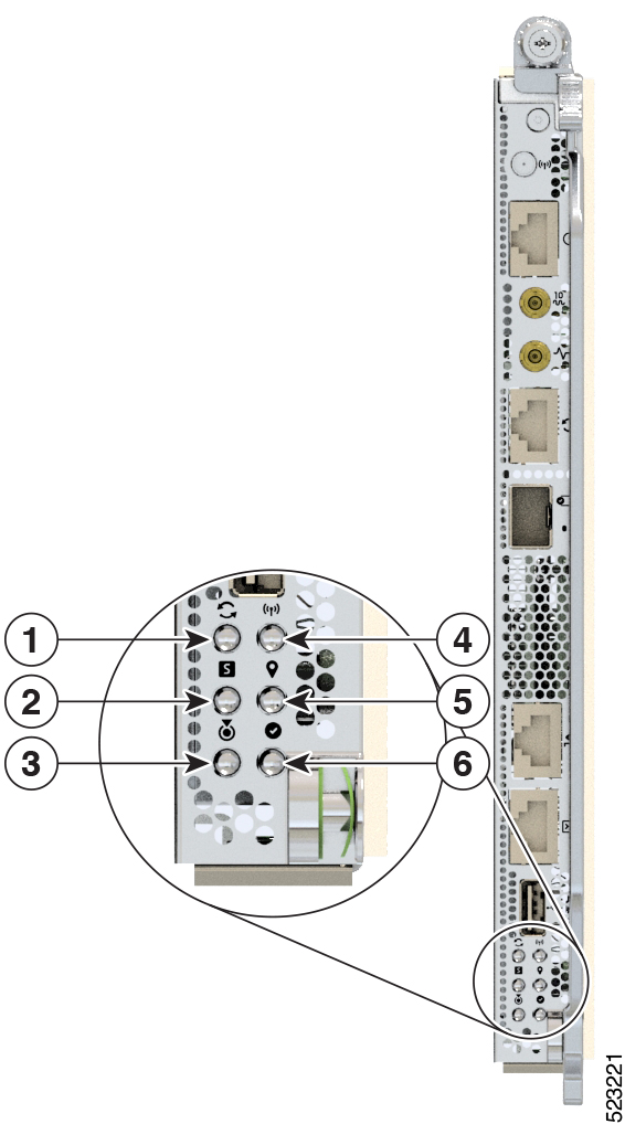
The Route Processor (RP) LEDs are located on the front of the chassis.

Figure 1. RP LEDs - Cisco 8608

1

Sync

2

Status

3

Attention

4

Management Activity

5

GPS

6

Active

Table 2. RP LED Descriptions

LED

Color

Status

Attention

Flashing Blue

The operator has activated this LED to identify this chassis.

Solid Blue

During bootup, if secure boot validation check fails on BIOS, it causes the router to halt the booting process. During run time, if secure JTAG detect tampering attempt to the CPU JTAG chain, then the router halts the CPU and sets the LED into this state.

Note


The router displays two LEDs. Solid Blue for Attention LED and Solid Red for Status LED.

Off

The operator has not activated this LED.

Status

Solid Amber

The module is in one of the following states:

  • Booting up

  • Shutting down

  • Power cycling

  • Installing image

Solid Green

This module is operational with no issues.

Flashing Green

Auto or Manual FPD upgrade is in-progress.

Flashing Amber

The module has an active minor alarm.

Flashing Red

The module has an active major or critical alarm.

Solid Red

The module is in one of the following states:

  • Power-up failure that prevents the CPU from booting.

  • During bootup, if secure boot validation check fails on BIOS, it causes the router to halt the booting process. During run time, if secure JTAG detect tampering attempt to the CPU JTAG chain, then the router halts the CPU and sets the LED into this state.

    Note


    The router displays two LEDs. Solid Blue for Attention LED and Solid Red for Status LED.

Off

The module is in one of the following states:

  • The module is in shutdown state by using either shutdown location location command in the EXEC mode or by using the hw-module shutdown location location command in the Config mode.

  • While the card is in running state, the ejector lever is opened that triggers the auto-shutdown operation for the module.

  • The module is placed in shutdown state by the software due to a hardware fault or a critical alarm condition.

Note


While in this state, the module can be safely removed from the router.

Active

Solid Green

This module is operational and in active redundancy state

Off

The module is in one of the following states:

  • The redundancy state, active or standby, is not decided yet.

  • This module is in the standby redundancy state.

Management Link

Green

The management port is linked up.

Off

The management port is not linked up.

Management Activity

Flashing Green

The management port is transmitting or receiving.

Off

The management port is not transmitting or receiving.

1588 Port Link

Green

The 1588 port is linked up.

Off

The 1588 port is not linked up.

1588 Port Activity

Flashing Green

The 1588 port is transmitting or receiving.

Off

The 1588 port is not transmitting or receiving.

Sync

Green

The frequency, time, and phase are synchronized with an external interface (BITS, GPS, Recovered RX Clock).

Amber

The time core is in free-run or holdover mode.

Off (Default after reset)

The time core clock synchronization is disabled. This is the default state after a reset.

GPS

Green

The GPS interface is provisioned and ports are turned on. Time of day (ToD), 1 packet per second (1PPS), and 10MHz are all valid.

Off (Default after reset)

Either the interface is not provisioned or the ports are not turned on. ToD, 1PPS, and 10MHz are not valid.

MPA LEDs

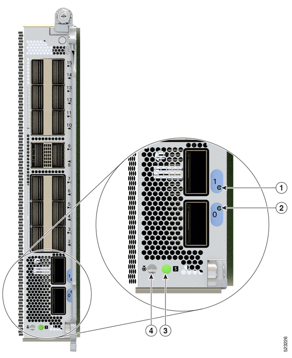
The Status LED and the Attention LED are located on the bottom of the MPA. The Link LEDs for each port are located on the right-side of the MPA, next to the ejector lever.

Figure 2. MPA LEDs

1

Link (Port 1)

2

Link (Port 0)

3

Status

4

Attention

Table 3. MPA LED Descriptions
LED Color Status

Attention

Flashing Blue

The operator has activated this LED to identify this module in the chassis.

Off

This module is not identified by the operator.

Status

Solid Amber

The module is in one of the following states:

  • Booting up

  • Shutting down

  • Power cycling

Solid Green

The module is operational with no issues.

Solid Red

The module has failed to power-up

Flashing Green

Auto or manual FPD upgrade is in-progress.

Flashing Red

The module has an active major or critical alarm.

Flashing Amber

The module has an active minor alarm.

Off

The module is in one of the following states:

  • The module is in shutdown state by using either shutdown location location command in the EXEC mode or by using the hw-module shutdown location location command in the Config mode.

  • While the card is in running state, the ejector lever is opened that triggers the auto-shutdown operation for the module.

  • The module is placed in shutdown state by the software due to a hardware fault or a critical alarm condition.

Note


While in this state, the module can be safely removed from the router.

Port (for each port)

Green

The port is administratively enabled and the link is up.

Amber

The port is administratively enabled and the link is down.

Off

The port is administratively shut down.

Power Supply LED

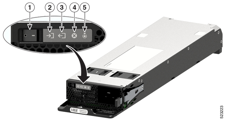
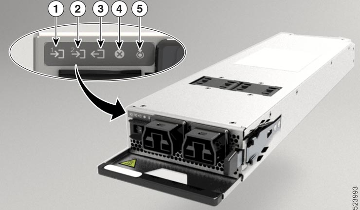
For the PSU3.2KW-ACPI and PSU4.3KW-HVPI PSU, the power module LEDs are located on the upper-left portion of the module. For the PSU3.2KW-DCPI PSU, the power module LEDs are located on the lower-right portion of the module.


Note


The following figure displays LEDs for an AC PSU.


Figure 3. Power Supply LEDs - PSU3.2KW-ACPI
Table 4. Power Supply LEDs Descriptions - PSU3.2KW-ACPI

1

On/Off Switch

2

Input Status

3

Output Status

4

Fault

5

Attention

Table 5. Power Supply LED Status Description - PSU3.2KW-ACPI

LED

Color

Status

Attention

Blinking Blue

The operator has configured this LED to identify this PSU.

Off

This device is not identified or configured.

Input Status

Green

Both inlet power present

Note


AC input voltage is 70 V minimum. AC PSU is single-input supply.

DC input voltage is -40 V minimum. DC PSU is dual-input supply.

Blinking Green

The module is in one of the following states:

  • Only one input power present

  • Hot unplugged

Note


AC input voltage is between 70 V and 85 V.

DC input voltage is:

  • between -27 V and -37 V

  • greater than -75 V and less than -77 V

Note


In DC dual-inputs mode, the absence of LED light indicates that DC input(s) are less than -26 V or greater than 77 V.

For a DC input voltage between -27 V and -37 V, or greater than -75 V and less than -77 V, the IN LED flashes on/off (0.5 sec ON / 0.5 sec OFF).

In single-input mode, the IN LED flashes on/off to indicate an ON state.

Off

The module is in one of the following states:

  • No input is present

  • Module firmware upgrade is in-progress

Note


AC input voltage is less than 70 V.

DC input voltage is less than -26 V.

Output Status

Green

The module is in one of the following states:

Output power is enabled

Blinking Green

The module is in one of the following states:

  • Output is out of regulation.

  • In sleep mode (Not present in DC-60)

Off

Firmware upgrade is in-progress.

Fault

Red

The module has detected a fault within the power supply unit.

Illuminates for 2-3 seconds after input is applied or disconnected through the front panel On/ Off switch (for AC-input power supplies) or On/ Off power button (for DC-input power supplies) or a circuit breaker.

Note


For DC input voltages that are greater than 77 VDC, this LED blinks on-off (0.5 sec ON / 0.5 sec OFF).

Blinking Red

Module firmware upgrade is in-progress

Figure 4. Power Supply LEDs - PSU4.3KW-HVPI
Table 6. Power Supply LEDs Descriptions - PSU4.3KW-HVPI

1

Input Status (Feed A)

2

Input Status (Feed B)

3

Output Status

4

Fault

5

Attention

Table 7. Power Supply LED Status Description - PSU4.3KW-HVPI

LED

Color

Status

Attention

Blinking Blue

The operator has configured this LED to identify this PSU.

Off

The operator has not configured this LED.

Input Status

Green

Both inlet power present

Note

 
The PSUs shall operate within specification from 85V-305V AC or 192-400V DC continuously.

Blinking Green

The module is in one of the following states:

  • Feed A or Feed B input power present

Note


AC input voltage is between 180V AC and 305V AC.

DC input voltage is between 192V DC and 400V DC

Off

The module is in one of the following states:

  • No input is present

  • Module firmware upgrade is in-progress

Note


AC input voltage is less than 180 V.

DC input voltage is less than 192 V.

Output Status

Green

The module is in one of the following states:

Output power is enabled

Blinking Green

The module is in one of the following states:

  • Output is out of range.

Off

The module is in one of the following states:
  • Firmware upgrade is in-progress.

  • Power tray switch is in Off position.

Fault

Red

The module has detected a fault within the power supply unit.

Illuminates for 2-3 seconds after the PSU is connected or disconnected through the front panel On/ Off switch (for AC-input power supplies) or On/ Off power button (for DC-input power supplies) or a circuit breaker.

Note


For DC input voltages that are greater than 400 VDC, this LED blinks on-off (0.5 sec ON / 0.5 sec OFF).

Blinking Red

Module firmware upgrade is in-progress

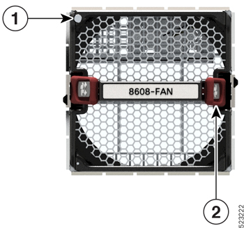
Fan Tray LED

The fan tray LED is located on the top left portion of the fan tray.

Figure 5. Fan Tray LED

1

Attention or Status

2

Latch

Table 8. Fan Tray LED Descriptions

LED

Color

Status

Attention or Status

Green

The fan is operational, fan speed (RPM) is within normal range.

Flashing Amber

The module is in one of the following states:

  • Fan speed (RPM) is outside normal range for one or more fans.

  • The module has a minor, major, or critical alarm.

Flashing Blue

The module is identified or activated.

Off

The module is not receiving power.

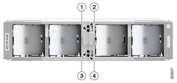
Switch Card LED

This section describes the LEDs and their status for Switch Card (SC) and Fan Board.

Figure 6. Switch Card LEDs

1

Fan Board Attention

2

Fan Board Status

3

Switch Card Attention

4

Switch Card Status

Table 9. Fan Board LED Descriptions

LED

Color

Status

Fan Board Attention

Flashing Blue

The operator has activated this LED to identify this module in the chassis.

Off

This module is not being identified.

Fan Board Status

Solid Amber

The module is in one of the following states:

  • The module is powered on.

  • Graceful chassis reload, shutdown, or reimage

Solid Green

This module is operational with no issues.

Flashing Green

Auto or Manual FPD upgrade is in-progress.

Flashing Amber

The module has an active minor alarm.

Flashing Red

The module has major or critical alarms.


Note


The Fan Board is hosted inside an SC. Fan Board controls the fan trays that are installed in the four fan tray slots. The fan tray slots are located in the front panel of the SC.


Table 10. Switch Card LED Descriptions

LED

Color

Status

Switch Card Attention

Flashing Blue

The operator has activated this LED to identify this module in the chassis.

Off

This module is not being identified.

Switch Card Status

Solid Amber

The module is in one of the following states:

  • The module is powered on.

  • Graceful chassis reload, shutdown, or reimage

Solid Green

This module is operational with no issues.

Solid Red

Power-up failure that prevents the card from powering up.

Flashing Green

Auto or manual FPD upgrade is in-progress.

Flashing Amber

The module has an active minor alarm.

Flashing Red

The module has major or critical alarms.

Off

The module is in one of the following states:

  • The module is in shutdown state by using either shutdown location location command in the EXEC mode or by using the hw-module shutdown location location command in the Config mode.

  • While the card is in running state, the ejector lever is opened that triggers the auto-shutdown operation for the module.

  • The module is placed in shutdown state by the software due to a hardware fault or a critical alarm condition.

Note


While in this state, the module can be safely removed from the router.

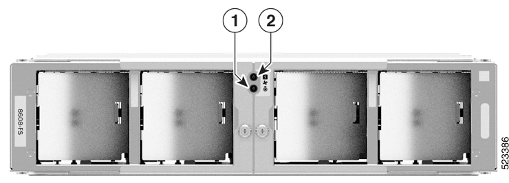
Fan Spinner LEDs

This section describes the Fan Spinner LEDs and their status.

These LEDs are for the fan board that controls the fan trays inserted in the four fan tray slots.

Figure 7. Fan Spinner LEDs

1

Fan Spinner Attention

2

Fan Spinner Status

Table 11. Fan Spinner LED Descriptions

LED

Color

Status

Fan Spinner Attention

Flashing Blue

The operator has activated this LED to identify this module in the chassis.

Off

This module is not being identified.

Fan Spinner Status

Solid Amber

The module is in one of the following states:

  • The module is powered on.

  • Graceful chassis reload, shutdown, or reimage

Solid Green

This module is operational with no issues.

Flashing Green

Auto or manual FPD upgrade is in-progress.

Flashing Amber

The module has an active minor alarm.

Flashing Red

The module has major or critical alarms.