Setup the Router

By following the guidelines provided on this page, you can set up the Cisco 8000 series routers quickly and efficiently.

Prerequisites to Setup Router

Complete the following prerequisite tasks to prepare the router for seamless setup.
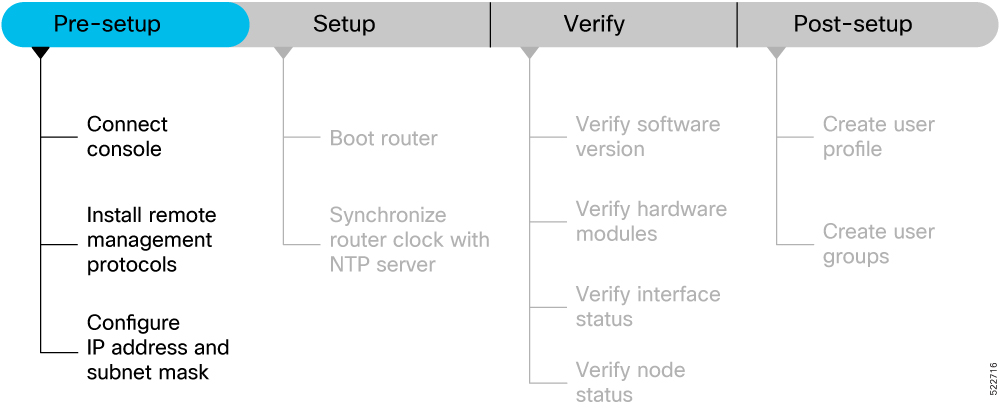
Figure 1. Pre-setup Workflow for the Cisco 8000 Series Routers

Workflow of the tasks involved in pre-setup of your Cisco 8000 series router

This section contains the following topics:

Connect Console Port to Terminal

The console port on the router is used to log into a router directly without a network connection using a terminal emulation program like HyperTerminal.

Procedure


Step 1

Connect the router to a terminal.

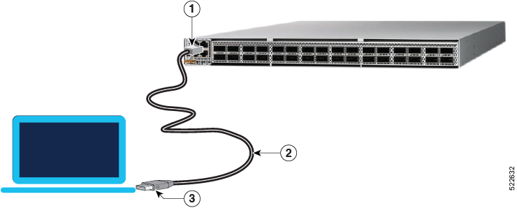
  1. Locate the console port on the router.

    Figure 2. Connect the Router to a Terminal

    Establish connection between the router and a terminal using the console port
    Table 1. Console Port and Cable Specifications

    1

    Routers console port

    2

    RJ-45 Rollover cable

    3

    • RJ-45/DSUB R/P adapter

    • RJ-45F/DB9F adapter

    • RJ-45/DSUB F/F adapter

  2. Connect the console (or rollover) cable to the console port on the router.

  3. Use the correct adapter to connect the other end of the cable to your terminal or PC.

Step 2

Configure the console port to match the following default port characteristics.

  1. Launch the terminal session.

  2. In the COM1 Properties window, select Port Settings tab, and enter the following settings:

    • Speed – 115200

    • Data Bits – 8

    • Parity – none

    • Stop bits – 1

    • Flow Control – none

Step 3

Click OK.

You should see a blinking cursor in the HyperTerminal window indicating successful connection to the console port.


Install Remote Management Protocols

The router can be accessed using remote management protocols, such as SSH, SCP, FTP, and Telnet. The SSH, SCP, and FTP management protocols are included in the ISO image by default. Telnet is an optional package.

Procedure


Install the remote management protocols.

To install Telnet, you can use either of the following options:

  • Install telnet package from the local directory of your router. The path to the local directory must be under /harddisk:/ location. The following example shows how you can install the xr-telnet-7.0.11v1.0.1-1.x86_64.rpm optional package:
    Router#install source /harddisk:/files xr-telnet-7.0.11v1.0.1-1.x86_64.rpm
  • Install telnet package from a configured repository.

    Router#install source install-repo xr-telnet

    For information on creating and accessing an external or local repository, see Create Repository to Access Install Files.


Setup the Router

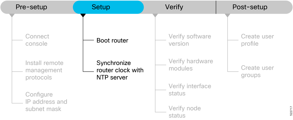
Complete the following tasks to bring up your router for further configurations.

Figure 3. Setup Workflow for the Cisco 8000 Series Router

Workflow of the tasks involved in setting up your Cisco 8000 series router

Boot the Router

After installing the hardware and connecting the console port to the terminal, boot the Cisco 8000 series router. The router completes the boot process using the pre-installed operating system image.

Before you begin

Ensure that you have completed the Prerequisites to Setup Router.

Procedure


Step 1

Power ON the router.

The router completes the boot process using the pre-installed operating system image. If the router is not pre-installed with an image, you can boot the router using PXE boot an externally bootable USB drive or PXE boot.

Note


Effective Cisco IOS XR Software Release 7.10.1, we have updated the bootup logs on the router to display the information of Secure Shell Daemon (SSHD) process. The SSHD process is a part of the Cisco IOS XR ISO installation service.

The updated bootup log message is:
Starting IOS-XR ISO Installation including sshd... 

[  OK ] IOS-XR ISO Installation including sshd. 

Step 2

After booting is complete, follow the prompt to create a username and password. This credential is used to log on to the IOS XR console and get to the router prompt. The following prompt appears:


!!!!!!!!!!!!!!!!!!!! NO root-system username is configured. Need to configure root-system username. !!!!!!!!!!!!!!!!!!!!

--- Administrative User Dialog ---


Enter root-system username:
% Entry must not be null.

Enter root-system username: cisco
Enter secret:
Use the 'configure' command to modify this configuration.
User Access Verification

Username: cisco
Password:

See the Recover Router From Boot Failure topic to resolve any boot failure issues.


Configure IP Address and Subnet Mask

Configure the IP address and subnet mask. The IP address and subnet mask for the Management Ethernet interface is used by the router for system management and remote communication.

Consult your network administrator or system planner to procure IP addresses and a subnet mask for the management interface.


Note


We recommend that you use a Virtual Private Network (VPN) routing and VPN Routing and Forwarding (VRF) on the Management Ethernet interface.


Procedure


Step 1

Configure the IP address and a subnet mask for the Management Ethernet interface.

  1. Configure the VRF.

    Example:

    Router(config)#vrf vrf1
    Router(config-vrf)#exit
  2. Configure the Management Ethernet Interface and set the VRF and IP address.

    Example:

    Router(config)#interface MgmtEth0/RSP0/CPU0/0
    Router(config)#vrf vrf1
    Router(config-if)#ipv4 address 10.10.0.1 255.0.0.0
    Router(config-if)#ipv4 virtual address vrf vrf1 10.10.0.1/8 

    Configure multiple interfaces in a similar way.

  3. Ensure that all available interfaces are discovered, and they in UP state.

    Example:

    Router(config-if)#no shutdown
    Router(config-if)#exit
  4. Configure a static route for communications with devices on other networks. Specify the IP address of the default gateway.

    Example:

    Router(config)#router static vrf vrf1 address-family ipv4 unicast 0.0.0.0/0 10.10.0.1
    Router(config)#commit
  5. SSH into the management port.

    Example:

    Router#conf t
    Router(config)#ssh server v2
    Router(config)#commit
    

Step 2

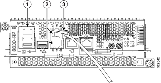
Connect the management port to the Ethernet network. The physical port Ethernet 0 on route processor is the management port.

Figure 4. Console Port and Management Ethernet Port

Console port and Management Ethernet port indicators on the router

1

Console RS-232 Serial Port RJ-45

2

Management Ethernet Port (10/100/1000-Mbps) RJ-45 (Copper) port

3

Management Port connected to the Ethernet network

Example:

Server# ssh root@10.10.0.1
/etc/ssh/ssh_config line 18: Unsupported option "rhostsrsaauthentication"
/etc/ssh/ssh_config line 19: Unsupported option "rsaauthentication"
Warning: Permanently added 'x.xx.xx.xxx' (ECDSA) to the list of known hosts.
Password:

Synchronize Router Clock with NTP Server

You must synchronize the IOS XR clock with the Network Time Protocol (NTP) server to avoid a deviation from true time.

NTP uses the concept of a stratum to describe how many NTP hops away a machine is from an authoritative time source. A stratum 1 time server typically has an authoritative time source (such as a radio or atomic clock, or a GPS time source) directly attached to the server. A stratum 2-time server receives its time through NTP from a stratum 1 time server, and so on.


Note


Cisco's implementation of NTP does not support stratum 1 service, and it is not possible to connect to a radio or atomic clock. We recommend that you obtain the time service for your network from the public NTP servers available on the IP Internet.


Procedure


Step 1

Synchronize the IOS XR clock with NTP server by going through the following example.

Example:

The NTP source is an IP address
Router(config)#ntp server NTP-source-IP-address
Example of NTP source is an IPv4 address:
Router(config)#ntp server 192.0.2.0
Example of NTP source is an IPv6 address:
Router(config)#ntp server 2001:DB8::1

Step 2

Commit the configuration.

Example:

Router(config-ntp)#commit

Step 3

Verify that the clock is synchronised with the NTP server.

Example:

Router#show ntp status
Clock is synchronized, stratum 3, reference is 192.0.2.0 nominal freq is 1000000000.0000 Hz, 
actual freq is 1000000000.0000 Hz, precision is 2**24 reference time is E12B1B02.8BB13A2F 
(08:42:42.545 UTC Tue Sep 17 2019) clock offset is -3.194 msec, root delay is 4.949 msec 
root dispersion is 105.85 msec, peer dispersion is 2.84 msec loopfilter state is 'FREQ' 
(Drift being measured), drift is 0.0000000000 s/s system poll interval is 64, last update 
was 124 sec ago authenticate is disabled

What to do next

Your router is now setup sucessfully. Perform prelimiary checks on the router to verify that the hardware and software components are functional.

Verify the Software and Hardware Status

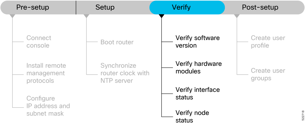
After logging into the console, perform preliminary checks to verify the default setup.

Figure 5. Verification Workflow for the Cisco 8000 Series Router Setup


Ensure that you have completed the procedures in Setup the Router section before proceeding with the following verification tasks:

Verify Software Version

View the software version installed on the router.

Procedure


Verify the latest version of the Cisco IOS XR software installed on the router.

Example:

Router#show version
Build Information:
Built By : user1
Built On : Thu Feb 02 10:06:56 UTC 2023
Build Host : host
Workspace : /ws
Version : 7.8.1
Label : 7.8.1

Note


You must upgrade the system if a new version of the system is available to avail the latest features on the router.

For more information about upgrading the software version, see Upgrade the Router.


Verify Hardware Modules

Cisco 8000 series routers have various hardware modules such as route processors, line cards, fan trays, and power modules installed on the router. Ensure that the firmware on various hardware components of the router is compatible with the installed Cisco IOS XR image. You also must verify that all the installed hardware and firmware modules are operational.

Procedure


Step 1

Verify the status of the hardware modules using the show platform command.

Example:

Router#show platform
Node Type State Config state
---------------------------------------------------------------
0/RP0/CPU0 8201-SYS(Active) IOS XR RUN NSHUT
Provision Network Devices using Zero Touch Provisioning
24
0/RP0/BMC0        8201-SYS            OPERATIONAL         NSHUT
0/PM0             PSU2KW-ACPE         OPERATIONAL         NSHUT
0/PM1             PSU2KW-ACPE         OPERATIONAL         NSHUT
0/FT0             FAN-1RU-PE          OPERATIONAL         NSHUT
0/FT1             FAN-1RU-PE          OPERATIONAL         NSHUT
0/FT2             FAN-1RU-PE          OPERATIONAL         NSHUT
0/FT3             FAN-1RU-PE          OPERATIONAL         NSHUT
0/FT4             FAN-1RU-PE          OPERATIONAL         NSHUT

Step 2

View the list of hardware and firmware modules that are detected on the router using the show hw-module fpd command.

Example:

Router#show hw-module fpd
FPD Versions
=================
Location         Card type     HWver       FPD device      ATR     Status       Running      Programd
------------------------------------------------------------------------------------------------------
0/RP0/CPU0       8800-RP        0.51       Bios            S       CURRENT      1.15         1.15
0/RP0/CPU0       8800-RP        0.51       BiosGolden      BS      CURRENT      1.15
0/RP0/CPU0       8800-RP        0.51       BmcFitPrimary   S       NEED UPGD    0.240        0.240
0/RP0/CPU0       8800-RP        0.51       BmcFpga         S       NEED UPGD    0.18         0.18
0/RP0/CPU0       8800-RP        0.51       BmcFpgaGolden   BS      CURRENT      0.19
0/RP0/CPU0       8800-RP        0.51       BmcTamFw        S       CURRENT      5.05         5.05
0/RP0/CPU0       8800-RP        0.51       BmcTamFwGolden  BS      CURRENT      5.05
0/RP0/CPU0       8800-RP        0.51       BmcUbootPrimary S       CURRENT      0.15         0.15
0/RP0/CPU0       8800-RP        0.51       EthSwitch               CURRENT      0.07         0.07
0/RP0/CPU0       8800-RP        0.51       EthSwitchGolden BP      CURRENT      0.07
0/RP0/CPU0       8800-RP        0.51       TimingFpga              CURRENT      0.11         0.11
0/RP0/CPU0       8800-RP        0.51       TimingFpgaGolden B      CURRENT      0.11
0/RP0/CPU0       8800-RP        0.51       x86Fpga          S      NEED UPGD    0.23         0.23
0/RP0/CPU0       8800-RP        0.51       x86FpgaGolden    BS     CURRENT      0.24
0/RP0/CPU0       8800-RP        0.51       x86TamFw         S      CURRENT      5.05         5.05
0/RP0/CPU0       8800-RP        0.51       x86TamFwGolden   BS     CURRENT      5.05

From the show hw-module fpd output, verify that all hardware modules that are installed on the chassis are listed. An unlisted module indicates that the module is either malfunctioning, or has not been installed properly. You must remove and reinstall the hardware module.

The fields in the show hw-module fpd output are:

  • FPD Device: Name of the hardware component, such as IO FPGA, IM FPGA, or BIOS. The Golden FPDs are not field upgradable.

  • Running: Current version of the firmware running on the FPD.

  • Programd: Version of the FPD programmed on the module

  • Status: Upgrade status of the firmware. The different states are:

Table 2. Status and Description of the Firmware Upgrade
Status Description
CURRENT The firmware version is the latest version.
READY The firmware of the FPD is ready for an upgrade.
NOT READY The firmware of the FPD is not ready for an upgrade.
NEED UPGD A new firmware version is available in the installed image. We recommend that you to perform an upgrade of the firmware version.
RLOAD REQ The upgrade is complete, and the ISO image requires a reload.
UPGD DONE The firmware upgrade is successful.
UPGD FAIL The firmware upgrade has failed.
BACK IMG The firmware is corrupt. Reinstall the firmware.
UPGD SKIP The upgrade is skipped because the installed firmware version is higher than the one available in the image.

Step 3

Upgrade the required firmware as required, using the upgrade hw-module location all fpd all command.

Example:

Router#upgrade hw-module location all fpd all
Alarms are created showing all modules that needs to be upgraded.

Active Alarms
-----------------------------------------------------------------------------------------------------------------
Location     Severity  Group      Set Time                  Description
-----------------------------------------------------------------------------------------------------------------
0/6/CPU0     Major     FPD_Infra  09/16/2019 12:34:59 UTC   One Or More FPDs Need Upgrade Or Not In Current State
0/10/CPU0    Major     FPD_Infra  09/16/2019 12:34:59 UTC   One Or More FPDs Need Upgrade Or Not In Current State
0/RP0/CPU0   Major     FPD_Infra  09/16/2019 12:34:59 UTC   One Or More FPDs Need Upgrade Or Not In Current State
0/RP1/CPU0   Major     FPD_Infra  09/16/2019 12:34:59 UTC   One Or More FPDs Need Upgrade Or Not In Current State
0/FC0        Major     FPD_Infra  09/16/2019 12:34:59 UTC   One Or More FPDs Need Upgrade Or Not In Current State
0/FC1        Major     FPD_Infra  09/16/2019 12:34:59 UTC   One Or More FPDs Need Upgrade Or Not In Current State

Note

 
The BIOS and IOFPGA upgrades require a restart of the router for the new version to take effect.

Step 4

Verify status of the modules after upgrade using the show hw-module fpd command.

Example:

Router#show hw-module fpd
Location      Card type     HWver      FPD device     ATR        Status       Running     Programd
---------------------------------------------------------------------------------------------------
0/RP0/CPU0    8800-RP       0.51       Bios              S          CURRENT    1.15       1.15
0/RP0/CPU0    8800-RP       0.51       BiosGolden        BS         CURRENT    1.15
0/RP0/CPU0    8800-RP       0.51       BmcFitPrimary     S          RLOAD REQ  0.240      0.241
0/RP0/CPU0    8800-RP       0.51       BmcFpga           S          RLOAD REQ  0.18       0.19
0/RP0/CPU0    8800-RP       0.51       BmcFpgaGolden     BS         CURRENT    0.19
0/RP0/CPU0    8800-RP       0.51       BmcTamFw          S          CURRENT    5.05       5.05
0/RP0/CPU0    8800-RP       0.51       BmcTamFwGolden    BS         CURRENT    5.05
0/RP0/CPU0    8800-RP       0.51       BmcUbootPrimary   S          CURRENT    0.15       0.15
0/RP0/CPU0    8800-RP       0.51       EthSwitch                    CURRENT    0.07       0.07
0/RP0/CPU0    8800-RP       0.51       EthSwitchGolden   BP         CURRENT    0.07
0/RP0/CPU0    8800-RP       0.51       TimingFpga                   CURRENT    0.11       0.11
0/RP0/CPU0    8800-RP       0.51       TimingFpgaGolden  B          CURRENT    0.11
0/RP0/CPU0    8800-RP       0.51       x86Fpga           S          RLOAD REQ  0.23       0.24
0/RP0/CPU0    8800-RP       0.51       x86FpgaGolden     BS         CURRENT    0.24
0/RP0/CPU0    8800-RP       0.51       x86TamFw          S          CURRENT    5.05       5.05
0/RP0/CPU0    8800-RP       0.51       x86TamFwGolden    BS         CURRENT    5.05

The status of the upgraded nodes shows that a reload is required.

Step 5

Reload the individual nodes that require an upgrade.

Example:

Router#reload location node-location

Step 6

Verify that all nodes that had required an upgrade now shows an updated status of CURRENT with an updated FPD version.

Example:

Router#show hw-module fpd
FPD Versions
=================
Location     Card type   HWver   FPD device      ATR      Status       Running     Programd
-------------------------------------------------------------------------------------------
0/RP0/CPU0   8800-RP     0.51     Bios            S        CURRENT      1.15        1.15
0/RP0/CPU0   8800-RP     0.51     BiosGolden      BS       CURRENT      1.15
0/RP0/CPU0   8800-RP     0.51     BmcFitPrimary   S        CURRENT      0.241       0.241
0/RP0/CPU0   8800-RP     0.51     BmcFpga         S        CURRENT      0.19        0.19
0/RP0/CPU0   8800-RP     0.51     BmcFpgaGolden   BS       CURRENT      0.19
0/RP0/CPU0   8800-RP     0.51     BmcTamFw        S        CURRENT      5.05        5.05
0/RP0/CPU0   8800-RP     0.51     BmcTamFwGolden  BS       CURRENT      5.05
0/RP0/CPU0   8800-RP     0.51     BmcUbootPrimary S        CURRENT      0.15        0.15
0/RP0/CPU0   8800-RP     0.51     EthSwitch                CURRENT      0.07        0.07
0/RP0/CPU0   8800-RP     0.51     EthSwitchGolden BP       CURRENT      0.07
0/RP0/CPU0   8800-RP     0.51     TimingFpga               CURRENT      0.11        0.11
0/RP0/CPU0   8800-RP     0.51     TimingFpgaGolden B       CURRENT      0.11
0/RP0/CPU0   8800-RP     0.51     x86Fpga          S       CURRENT      0.24        0.24
0/RP0/CPU0   8800-RP     0.51     x86FpgaGolden    BS      CURRENT      0.24
0/RP0/CPU0   8800-RP     0.51     x86TamFw         S       CURRENT      5.05        5.05
0/RP0/CPU0   8800-RP     0.51     x86TamFwGolden   BS      CURRENT      5.05

Note


For more information on upgrading FPDs, see the Upgrading Field-Programable Device chapter.


Verify Interface Status

All available interfaces must be discovered by the system after booting the Cisco 8000 Series Router. Interfaces not discovered might indicate a malfunction in the unit.

Procedure


Use the show ipv4 interfaces brief or show ipv6 interfaces brief command to view the interfaces discovered by the system.

Example:

Router#show ipv4 interfaces brief
Interface             IP-Address        Status         Protocol      Vrf-Name
------------------------------------------------------------------------------
HundredGigE0/0/0/0    unassigned        Shutdown       Down          default
HundredGigE0/0/0/1    unassigned        Shutdown       Down          default
HundredGigE0/0/0/2    unassigned        Shutdown       Down          default
HundredGigE0/0/0/3    unassigned        Shutdown       Down          default
HundredGigE0/0/0/4    unassigned        Shutdown       Down          default
HundredGigE0/0/0/5    unassigned        Shutdown       Down          default
HundredGigE0/0/0/6    unassigned        Shutdown       Down          default
HundredGigE0/0/0/7    unassigned        Shutdown       Down          default
-------------------------------- <snip> -------------------------------------
TenGigE0/0/0/18/0     unassigned        Up             Up            default
TenGigE0/0/0/18/1     unassigned        Up             Up            default
TenGigE0/0/0/18/2     unassigned        Up             Up            default
TenGigE0/0/0/18/3     unassigned        Up             Up            default
MgmtEth0/RP0/CPU0/0   10.10.10.1        Up             Up            default

When a router is turned ON for the first time, all interfaces are in the unassigned state.

Ensure that the total number of interfaces that are displayed in the result matches with the actual number of interfaces present on the router, and that the interfaces are created according to the type of line cards displayed in show platform command.


Verify Node Status

A node can be a specified location, or the complete hardware module in the system. You must verify that the software state of all route processors, line cards, and the hardware state of fabric cards, fan trays, and power modules are listed, and their state is OPERATIONAL. This indicates that the IOS XR console is operational on the cards.

Procedure


Verify the operational status of the node using the show platform command.

Example:

Router#show platform
Node          Type                 State          Config state
---------------------------------------------------------------
0/RP0/CPU0    8800-RP(Active)      IOS XR RUN     NSHUT
0/RP0/BMC0    8800-RP              OPERATIONAL    NSHUT
0/RP1/CPU0    8800-RP(Standby)     IOS XR RUN     NSHUT
0/RP1/BMC0    8800-RP              OPERATIONAL    NSHUT
0/0/CPU0      8800-LC              IOS XR RUN     NSHUT
0/11/CPU0     8800-LC              IOS XR RUN     NSHUT
0/FC0         8800-FC              OPERATIONAL    NSHUT
0/FC3         8800-FC              OPERATIONAL    NSHUT
0/FT0         8800-FAN             OPERATIONAL    NSHUT
0/FT1         8800-FAN             OPERATIONAL    NSHUT
0/FT2         8800-FAN             OPERATIONAL    NSHUT
0/FT3         8800-FAN             OPERATIONAL    NSHUT
0/PT0         FAM7000-ACHV-TRAY    OPERATIONAL    NSHUT
Table 3. Card Type, Node Status, and Description

Card Type

State

Description

All

UNKNOWN

Error – Internal card record is not available

All

IDLE

Error – Card state is not initialized

All

DISCOVERED

Card is detected

All

POWERED_ON

Card is powered on

RP, LC

BIOS_READY

Card BIOS is up

RP, LC

IMAGE_INSTALLING

Image is being downloaded or installed

RP, LC

BOOTING

Image is installed and the software is booting up

RP, LC

IOS_XR_RUN

Software is operating normally and is functional

RP, LC

IOS_XR_INITIALIZING

Software is initializing

FC, FT, PT, PM

OPERATIONAL

Card is operating normally and is functional

RP, LC, FC

RESET

Card is undergoing reset

RP, LC

REIMAGE

Card is pending reimage

RP, LC, FC

SHUTTING_DOWN

Card is shutting down as a result of a fault condition, user action or configuration

RP, LC, FC

SHUT_DOWN

Card is shutdown due to a fault condition, user action or configuration

FC

ONLINE

RP is able to access this remote card

LC

DATA_PATH_POWERED_ON

Forwarding complex is powered ON

RP (Active)

SHUTTING_REMOTE_CARDS

Active RP card is in the process of shutting down other cards as part of a chassis reset

RP (Standby), LC, FC

WAITING_FOR_CHASSIS_RESET

Card is shutdown and is waiting for the chassis to be reset

RP, LC

WDOG_STAGE1_TIMEOUT

Card CPU failed to reset the hardware watchdog

RP, LC

WDOG_STAGE2_TIMEOUT

Hardware watchdog has timed out waiting for the card CPU to reset itself

RP, LC, FC

FPD_UPGRADE

One or more FPD upgrades are in progress

FC

CARD_ACCESS_DOWN

RP is unable to access this remote card

RP (standby only), LC

BOOT HOLD

In a multinode system, any node reloads that occur during a transaction that are not initiated as part of the installation shows a BOOT HOLD state. The node continues to be in this state until the transaction is either committed or cancelled


What to do next

This completes verification of the basic router setup. You can now complete the post-setup tasks where you manage user profiles and groups.

Complete Post-setup Tasks

You must create user profiles and user groups to manage your system, install software packages, and configure your network.


Note


Users created in the System Admin VM are different from the ones created in XR VM. As a result, the username and password of a System Admin VM user cannot be used to access the XR VM, and vice versa.


Every user is authenticated using a username and a password. The authentication, authorization, and accounting (AAA) commands help with these services:

  • Create users, groups, command rules, or data rules

  • Change the disaster-recovery password

IOS-XR and Linux have separate AAA services and IOS XR AAA is the primary AAA system. A user who is created through IOS-XR can log in directly to the EXEC prompt when connected to the router, while a user created through Linux can connect to the router, but can log in to the bash prompt. The user must log in to IOS XR explicitly, to access the IOS-XR EXEC prompt.

You must configure the IOS-XR AAA authorization to restrict users from uncontrolled access. If AAA is not configured, the command and data rules associated to the groups that are assigned to the user are ignored. A user can have full read/write access to IOS XR configuration through Network Configuration Protocol (NETCONF), google-defined Remote Procedure Calls (gRPC), or any YANG-based agents. To avoid granting uncontrolled access, enable AAA before setting up any configuration. To gain an understanding about AAA, and to explore the AAA services, see the Configuring AAA Services chapter in the System Security Configuration Guide for Cisco 8000 Series Routers.

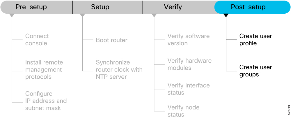
The following image provides you an overview of the various tasks that are involved in the Cisco 8000 Series Routers post-setup procedure.

Figure 6. Post-setup Workflow for the Cisco 8000 Series Router

Workflow of the tasks involved after setting up your Cisco 8000 series router

Ensure that you have completed the Setup the Router and Verify the Software and Hardware Status tasks before you perform the following tasks:

Create User Profile

You can create new users and include the user in a user group with certain privileges. The router supports a maximum of 1024 user profiles.

Perform the following steps to create a user profile:

Procedure


Step 1

Create a user, provide a password and assign the user to a group. For example, user1 is the user, password is pw123, and the group is root-lr.

Example:

Router#config

/* Create a new user */
Router(config)#username user1

/* Set a password for the new user */
Router(config-un)#password pw123

/* Assign the user to group root-lr */
Router(config-un)#group root-lr

All users have read privileges. The root-lr users inherit write privileges where users can create configurations, create new users, and so on.

Enable display of login banner: The US Department of Defense (DOD)-approved login banner provides information such as number of successful and unsuccessful login attempts, time stamp, login method, and so on. The banner is displayed before granting access to devices. The banner also ensures privacy and security that is consistent with applicable federal laws. In addition, the system keeps track of logins, right from the system boot, or as soon as the user profile is created.

You can enable or diable the login login banner by using the login-history enable and login-history disable commands.

Note

 
Login notifications get reset during a router reload.

Step 2

Run the show running-config username user1 command to verify the state of login banner.

Example:

Router(config-un)#show running-config username NAME1
 Fri Jan 29 13:55:28.261 UTC
 username NAME1 
 group UG1
 secret * ********** 
 password * ******
 login-history enable

Step 3

Commit the configuration.

Example:

Router(config-un)#commit

The user profile is created and allowed access to the router based on the configured privileges.


Create User Groups

You can create a new user group to associate command rules and data rules with it. The command rules and data rules are enforced on all users that are part of the user group. The router supports a maximum of 32 user groups.

Before you begin

Ensure that you have created a user profile. See Create User Profile.

Procedure


Step 1

Create a new user group.

Example:

Router#config

/* Create a new user group, group1 */
Router#(config)#group group1

/* Specify the name of the user, user1 to assign to this user group */
Router#(config-GRP)#username user1

Step 2

Commit the configuration.

Example:

Router(config-GRP)#commit

What to do next

This completes the router setup and verification process. You can now proceed with upgrading the software, installing RPMs, SMUs and bug fixes based on your requirement.