Cisco ACI Multi-Site Service Integration
Starting with Release 2.0(1), Cisco ACI Multi-Site supports service graphs with a load balancer and two-node service graphs with a load balancer and a firewall, in addition to the previously supported single-node graphs with a firewall.
Previous releases provided single-node service graphs support by applying PBR policies on the consumer's site for East-West traffic. In order to support two-node graphs in East-West scenario, PBR policies are now applied on the provider's site. While it prevents traffic from bouncing between sites in return data path, it requires a subnet to be configured under the consumer EPGs. In North-South scenario, PBR policies are still applied on the non-border leaf as they were in previous release.
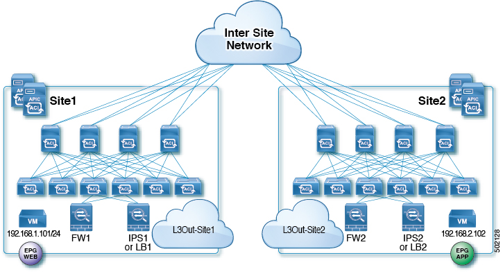
To support the use cases described in this chapter, the following topology is required for service nodes:
-
Each site has individual active/standby service node pair
-
Layer 4 to Layer 7 devices are in un-managed mode
-
VRFs are stretched across sites
-
Consumer and provider EPGs have cross-site contract
In addition to the topology requirements above, keep in mind the following considerations:
-
External and internal connector of a node can be same logical interface
-
In case of East-West traffic, a subnet must be configured under consumer EPGs
-
In case of East-West inter-VRF traffic, a subnet must be configured on both consumer and provider EPGs
-
In case of North-South traffic, policies are applied on the non-border leaf
-
Shared service scenario is supported for East-West traffic, but not for North-South traffic
A sample topology used throughout the use-cases in this chapter is shown below:
Single-Node Service Graphs
East-West FW Service Graph
This is the use case for East-West communication with a Firewall (FW) between endpoints in the same VRF or different VRFs across sites.
The following two local PBR policies are required for the Service Graph:
-
PBR policy on FW's external connector to redirect consumer-to-provider traffic to FW's external interface
-
PBR policy on FW's internal connecter to redirect provider-to-consumer traffic to FW's internal interface
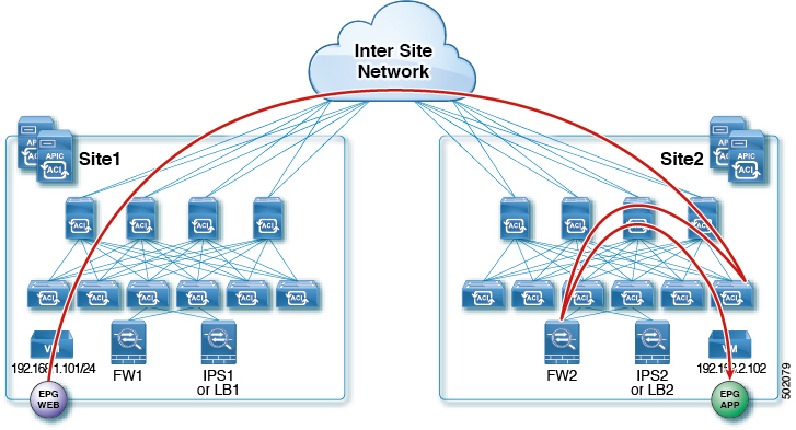
The following figures show incoming traffic packet flow from consumer on Site1 to provider on Site2:
-
Consumer leaf does not apply any rules, forwards traffic to the provider
-
Provider leaf applies policy and send traffic to FW2
-
Finally, traffic is sent to the provider EPG
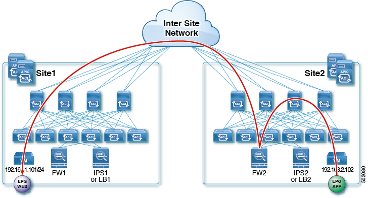
The following figures shows return traffic packet flow from provider on Site2 to consumer on Site1:
-
Provider leaf applies policy to redirect traffic to FW2
-
Traffic is then sent to consumer on Site1
-
Consumer leaf does not apply any rules, forwards traffic to consumer EPG
North-South FW Service Graph
This is the use case for North-South communication with a Firewall (FW) between endpoints in the same VRF across sites.
The following figures show incoming traffic packet flow from consumer on Site1 to provider on Site2:
-
Consumer border leaf does not apply any rules, forwards traffic to the provider
-
Non-border leaf on provider's site applies policy and sends traffic to FW2's external interface
-
Finally, traffic is sent to the EPG
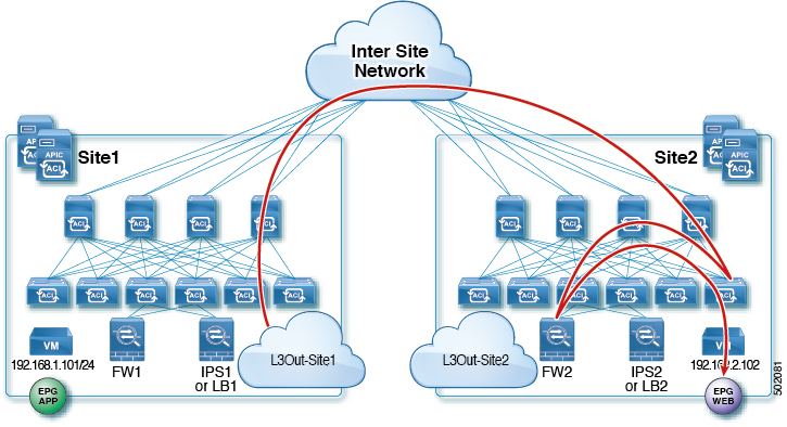
The following figures shows return traffic packet flow from provider on Site2 to consumer on Site1:
-
Non-border leaf on provider's site applies policy to redirect traffic to FW2's internal connector
-
Traffic is then sent out the Site2's L3Out
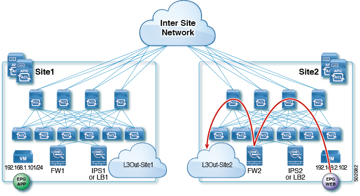
East-West LB Service Graph
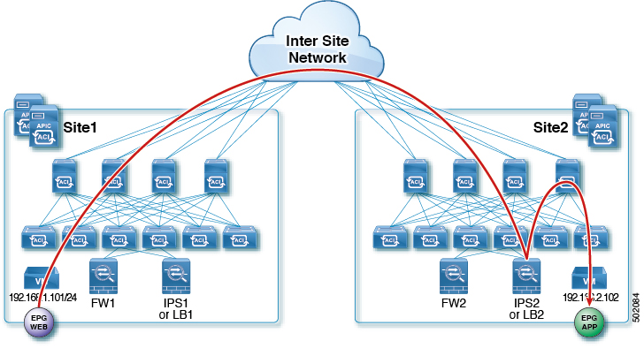
This is the use case for East-West communication with the Load-Balancer (LB) between endpoints in the same VRF or different VRFs across sites. Service Graphs with LB are different from the ones with a Firewall (FW), because in this case the traffic is destined for the VIP of the LB. This use-case describes a scenario where the LB is in one site with local provider EPG and consumer is in another site.
The following figures shows incoming traffic packet flow from consumer on Site1 to provider (EPG App) on Site2:
-
Consumer leaf does not apply any rules, forwards traffic to the provider
-
Traffic is forwarded to LB2's VIP
-
Finally, traffic is sent to the provider EPG
 Note |
The example in this section uses no SNAT on the load-balancer. PBR is for return traffic to LB, as such if LB does SNAT, PBR is not necessary. Also, keep in mind that in case of no SNAT and PBR, the LB's VIP and its real servers must be in same site. |
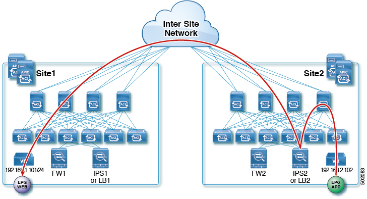
The following figures shows return traffic packet flow from provider on Site2 to consumer on Site1:
-
Provider leaf applies policy to redirect traffic to LB2
-
Traffic is then sent to consumer on Site1
-
Consumer leaf does not apply any rules, forwards traffic to consumer EPG
North-South LB Service Graph
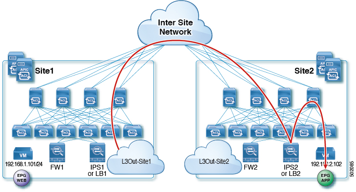
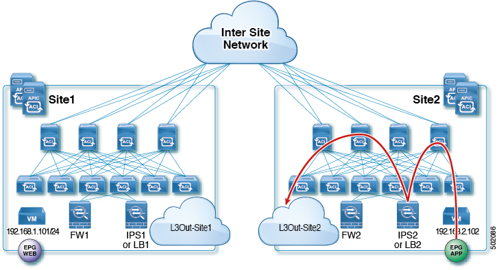
This is the use case for North-South communication with a Load-Balancer (LB) between endpoints in the datacenter and outside. The following diagram shows the packet flow for a scenario where L3Out traffic enters from the Site that is not hosting the LB for which the traffic is directed (VIP is in different site). In this we have L3Out as Consumer and regular EPG as provider. In this case policy is always applied on the provider site's non-border leaf.
The following figures show incoming traffic packet flow from consumer on Site1 to provider on Site2:
-
Consumer border leaf does not apply any rules, forwards traffic to VIP on the Site2
-
Non-border leaf on provider's site applies policy and traffic is forwarded to the LB
-
Finally, traffic is sent to the provider EPG from LB
 Note |
The example in this section uses no SNAT on the load-balancer. PBR is for return traffic to LB, as such if LB does SNAT, PBR is not necessary. Also, keep in mind that in case of no SNAT and PBR, the LB's VIP and its real servers must be in same site. |
The following figures shows return traffic packet flow from provider on Site2 to consumer on Site1:
-
Non-border leaf on provider's site applies policy to redirect traffic to LB
-
Traffic is then sent out the Site2's L3Out
Two-Node Service Graphs
East-West FW and IPS Service Graph
This is the use case for East-West communication with a Firewall (FW) and an Intrusion Prevention System (IPS) between endpoints in the same VRF or different VRFs across sites.
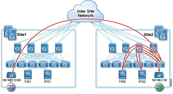
The following figures shows incoming traffic packet flow from consumer on Site1 to provider on Site2:
-
Consumer leaf does not apply any rules, forwards traffic to the provider
-
Provider leaf applies policy and send traffic to FW2's external interface
-
Traffic is then redirected back to the provider leaf and then to IPS2's external interface
-
Finally, traffic is sent to the provider EPG
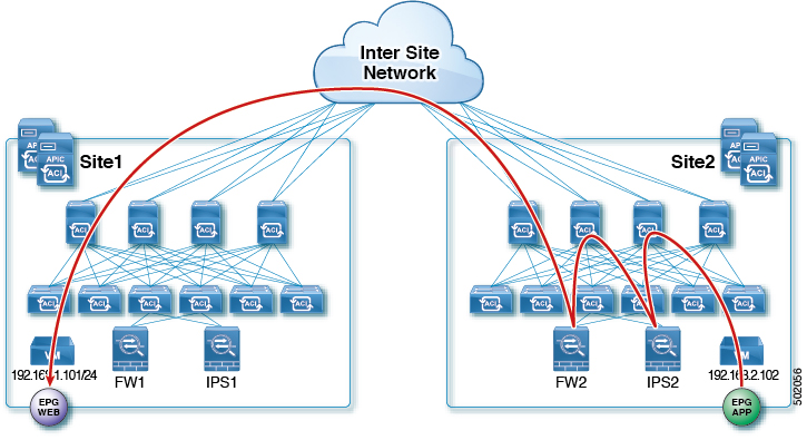
The following figures shows return traffic packet flow from provider on Site2 to consumer on Site1:
-
Provider leaf applies policy to redirect traffic to IPS2's internal connector
-
Traffic is then redirected to FW2's internal connector
-
Traffic is then sent to consumer on Site1
-
Consumer leaf does not apply any rules, forwards traffic to consumer EPG
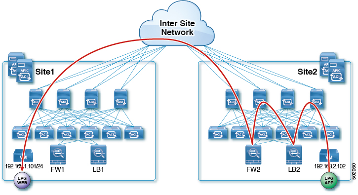
East-West FW and LB Service Graph
This is the use case for East-West communication with the Firewall (FW) and Load-Balancer (LB) between endpoints in the same VRF or different VRFs across sites. This is a common design for traffic within the application that requires the server load-balancing for high availability and scale.
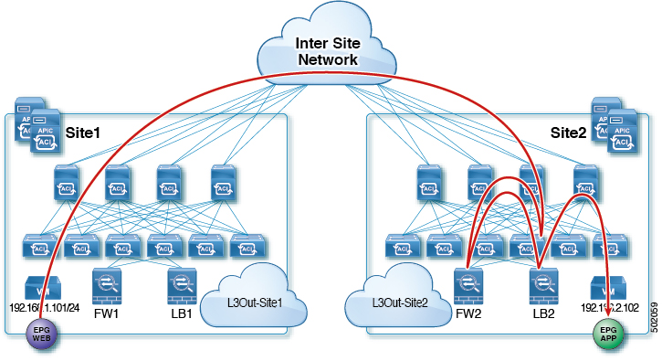
The following figures shows incoming traffic packet flow from consumer on Site1 to provider on Site2:
-
Consumer leaf does not apply any rules, forwards traffic to the provider
-
Provider leaf where the LB2's VIP is connected applies policy and send traffic to FW2's external interface
-
Traffic is then redirected to LB2
-
Finally, traffic is sent to the provider EPG
The following figures shows return traffic packet flow from provider on Site2 to consumer on Site1:
-
Provider leaf applies policy to redirect traffic to LB2
-
Traffic is then redirected to FW2's internal connector
-
Traffic is then sent to consumer on Site1
-
Consumer leaf does not apply any rules, forwards traffic to consumer EPG

 Feedback