TrustSec Configurations
The following configurations are required to deploy TrustSec on the network:

* Method used for the CVD.
Define and Create SGTs and Policies Using Cisco DNA Center
-
From the Cisco DNA Center web interface, navigate to Policy > Group-Based Access Control.
-
Click the Security Groups tab.
-
Click Create Security Group.
-
Fill out Name and optional Tag Value.
-
Click Save Now.
-
Click the Deploy link.
After creating the SGTs in Cisco DNA Center, the policy matrix can be updated to suit the enforcement intent. To make changes to the TrustSec policy matrix in DNA Center, do the following:
-
From the Cisco DNA Center web interface, navigate to Policy > Group-Based Access Control.
-
Click the Policies tab.
-
Click the square of the source and destination pair for which there needs to be a permit or deny contract.
-
On the Create Policy slide-in pane, click the Change Contract link and choose the appropriate option (Permit IP, Deny IP, and so on). Click the Change button.
-
Click the Deploy link at the top of the matrix.
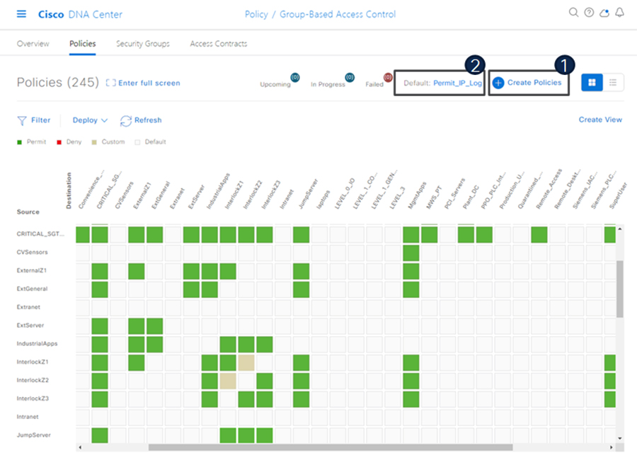
The following figure shows the TrustSec policy matrix in Cisco DNA Center. The Create Policies button (1) is used to create a new policy and the Default link (2) allows you to change the default action on the policy. For a default deny policy, choose the Deny_IP default action.
Warning: Don’t change default action to deny until all TrustSec elements have been configured and the policy has been tested with monitoring mode or log analysis.

Define ISE as the AAA Server using Cisco DNA Center
When a device is provisioned in the inventory, Cisco DNA Center configures AAA server information, CTS authorization commands, and RADIUS server groups. In addition, Cisco DNA Center configures the device on the ISE PAN and propagates any subsequent updates for the device to the ISE PAN.
Note: AAA server (ISE) settings for a given area should be configured in Design > Network Settings > Network.
-
From the DNA Center web interface, navigate to Provision > Network Devices > Inventory.
-
From the device list, check the box for the device to be provisioned.
-
From the Actions drop-down list, choose Provision > Provision device.
-
If the device is not assigned to a site, the wizard will show the Assign Site page. Click the Choose a site link and choose the desired Site. Click the Save button, then click the Next button. (Note that if Site assignment was done previously no action is needed here).
-
On the Advanced Configuration step, choose the device from the Devices list if there are any template settings to be configured. When finished, or if no template is applied, click the Next button.
-
On the Summary page, review the configuration to be added to the device. Click the Deploy button.
After the device has been provisioned, it will be in the device list of the specified Site.
Note: Provisioning a device that has already been configured with AAA before being discovered will fail. Remove any AAA configuration before pushing AAA using Cisco DNA Center.
Enable Device Tracking on Access Ports using Cisco DNA Center
Cisco DNA Center will automatically configure device tracking when a device is assigned to a site that has the wired client data collection enabled in its Telemetry settings (enabled by default). To verify the current setting, navigate to Design > Network Settings > Telemetry.
Configure Port-Based Authentication on the Access Switches
The following CLI output is provided as an example of policy. It can be deployed using Cisco DNA Center templates.
Example AAA Policy
class-map type control subscriber match-all
AAA_SVR_DOWN_AUTHD_HOST
match result-type aaa-timeout
match authorization-status authorized
!
class-map type control subscriber match-all
AAA_SVR_DOWN_UNAUTHD_HOST
match result-type aaa-timeout
match authorization-status unauthorized
!
class-map type control subscriber match-all
AI_IN_CRITICALSGT_AUTH
match activated-service-template IA_CRITICAL_SGT
!
class-map type control subscriber match-none
AI_NOT_IN_CRITICALSGT_AUTH
match activated-service-template IA_CRITICAL_SGT
!
class-map type control subscriber match-all DOT1X
match method dot1x
!
class-map type control subscriber match-all DOT1X_FAILED
match method dot1x
match result-type method dot1x authoritative
!
class-map type control subscriber match-all
DOT1X_MEDIUM_PRIO
match authorizing-method-priority gt 20
!
class-map type control subscriber match-all DOT1X_NO_RESP
match method dot1x
match result-type method dot1x agent-not-found
!
class-map type control subscriber match-all DOT1X_TIMEOUT
match method dot1x
match result-type method dot1x method-timeout
!
class-map type control subscriber match-any
IA_CRITICAL_SGT
match activated-service-template IA_CRITICAL_SGT
!
class-map type control subscriber match-all MAB
match method mab
!
class-map type control subscriber match-all MAB_FAILED
match method mab
match result-type method mab authoritative
!
policy-map type control subscriber IA_DOT1X_MAB_POLICIES
event session-started match-all
10 class always do-until-failure
10 authenticate using mab retries 3 retry-time 0 priority
10
20 authenticate using dot1x retries 3 retry-time 0
event authentication-failure match-first
5 class DOT1X_FAILED do-until-failure
10 terminate dot1x
20 authenticate using mab priority 20
10 class AAA_SVR_DOWN_UNAUTHD_HOST do-until-failure
10 activate service-template IA_CRITICAL_SGT
20 authorize
30 authentication-restart 60
40 pause reauthentication
20 class AAA_SVR_DOWN_AUTHD_HOST do-until-failure
10 authentication-restart 5
20 authorize
30 class DOT1X_NO_RESP do-until-failure
10 terminate dot1x
20 authenticate using mab priority 20
40 class MAB_FAILED do-until-failure
10 terminate mab
20 authentication-restart 60
60 class always do-until-failure
10 terminate dot1x
20 terminate mab
30 authentication-restart 60
event agent-found match-all
10 class always do-until-failure
10 terminate mab
20 authenticate using dot1x priority 10
event aaa-available match-first
10 class AI_IN_CRITICALSGT_AUTH do-until-failure
10 clear-session
20 class AI_NOT_IN_CRITICALSGT_AUTH do-until-failure
10 resume reauthentication
event violation match-all
10 class always do-until-failure
10 restrict
Example Interface Configuration using ‘foreach’ loops
#foreach($interface in $accessInterfaces)
interface $interface.portName
description endpoint
switchport access vlan $dataVlan
switchport mode access
device-tracking attach-policy IPDT_POLICY
#if($netflowPolicy)
ip flow monitor dnacmonitor input
#end
access-session port-control auto
mab
dot1x pae authenticator
spanning-tree portfast
service-policy type control subscriber
IA_DOT1X_MAB_POLICIES
service-policy input CIP-PTP-Traffic
service-policy output PTP-Event-Priority
#if($stormControl)
storm-control broadcast level 3 1
#end
exit
vlan $dataVlan
#end
#foreach($uplinkInterface in $trunkInterfaces)
interface $uplinkInterface.portName
description trunk
switchport trunk allowed vlan $vlans
switchport mode trunk
#if($cts)
cts manual
policy static sgt $uplinkSGT trusted
exit
exit
#end
vlan $vlans
#end
Configure Static Entries and Fallback Policy to Allow Communication in the event of an ISE error
The following configurations are recommended for a default deny policy to guarantee connectivity for critical services:
Change the SGT assigned to switches from “Unknown” to “TrustSec Devices” in ISE
By default, the “Unknown” SGT is configured for network device authorization and changing it to “TrustSec Device” gives more visibility and helps to create SGACLs specifically for switchinitiated traffic.
-
From the ISE web UI, navigate to Work Centers > TrustSec > TrustSec Policy > Network Device Authorization and click the Edit link to update the Security Group.
Create static IP to SGT mappings on the TrustSec domain switches
Having local IP to SGT mappings ensures connectivity is up and connectivity to the critical resources are intact if connectivity to ISE is interrupted. In the example below ISE, DNAC, and the enforcement switch IP addresses are assigned the SGT for TrustSec devices (in this example 9043). Optionally, the subnet for the Cell/Area zone is assigned tag 911 to allow inter-Cell/Area zone communication for all devices when ISE is not reachable. Once ISE is reachable again, mappings from ISE learned via SXP will take priority. The 911 tag should only be used when ISE is not available.
cts role-based sgt-map 10.13.48.132 sgt 9043
cts role-based sgt-map 10.13.48.184 sgt 9043
cts role-based sgt-map 10.17.10.1 sgt 9043
cts role-based sgt-map 10.17.10.0/24 sgt 911
Create a Fallback SGACL in the event ISE communication is lost
An SGT mapping is of no use until a relevant SGACL is assigned and hence our next step would be to create an SGACL that acts as a local Fallback in case ISE nodes go down (when ISE services are down, SGACLs and IP SGT mappings are not downloaded dynamically). In the example below we allow communication from the enforcement switch to critical services (ISE and DNA Center). Optionally, policies are created to allow external communication for all devices in the Cell/Area zone (911 tag).
ip access-list role-based FALLBACK
permit ip
cts role-based permissions from 9043 to 9043 FALLBACK
cts role-based permissions from 911 to 0 FALLBACK
cts role-based permissions from 0 to 911 FALLBACK
cts role-based permissions from 911 to 911 FALLBACK
cts role-based permissions from 9043 to 911 FALLBACK
cts role-based permissions from 911 to 9043 FALLBACK
Propagation on Distribution Switches and Core Switches
To ensure the SGT remains inside the packet throughout the TrustSec domain, configure inline tagging on links between the core and distribution switches.
Note: that this process may be disruptive since the interface bounces when configuring inline tagging. Plan accordingly to disrupt a single link at a time. When using port channels, remove the interfaces from the port channel, add configuration, and then add interfaces to the port channel again.
interface $uplinkInterface.portName
description trunk
switchport trunk allowed vlan $vlans
switchport mode trunk
cts manual
policy static sgt $uplinkSGT trusted
Each switch within the TrustSec domain must also be configured as an SXP listener. The speaker may be ISE or access switches connected below.
cts sxp enable
cts sxp default password 0 $sharedKey
cts sxp connection peer $peerIP source
$sourceIP.ipv4Address password default mode local listener
hold-time 0 0
Propagation on Industrial Switches
If using inline tagging in the industrial switches (for example, when using L2NAT), configure inline tagging on both ports of the link.
Note: that this process may be disruptive because the interface bounces when configuring inline tagging. To ensure connectivity is not lost, configure the farther switch first or use out of band connectivity. If configuring a port channel, links need to be removed from the port channel first and add back after configuration is completed.
interface $uplinkInterface.portName
description trunk
switchport trunk allowed vlan $vlans
switchport mode trunk
cts manual
policy static sgt $uplinkSGT trusted
If configuring SXP, refer to the following configurations:
-
Trustsec SXP – Speaker role, used when communicating bindings to upstream switches
cts sxp enable cts sxp default password 0 $sharedKey cts sxp connection peer $peerIP source $sourceIP.ipv4Address password default mode local speaker hold-time 0 0 -
Trustsec SXP – Listener role, used when receiving bindings from ISE or access switches
cts sxp enable
cts sxp default password 0 $sharedKey
cts sxp connection peer $peerIP source
$sourceIP.ipv4Address password default mode local listener
hold-time 0 0
Configure SXP in ISE
The following configuration creates a domain filter and adds an SXP device.
-
From the ISE web UI, navigate to Work Centers > TrustSec > SXP > SXP Devices.
-
Click the Assign SXP Domain link, even if no SXP devices are present.
-
On the SXP Domain Assignment window, click the Create New SXP Domain link.
-
Enter a name for the new domain.
-
Click the Create button.
-
Navigate to Work Centers > TrustSec > SXP > SXP Devices.
-
Click the Add button.
-
Enter the device details: name, IP address, SXP role (speaker), password type, SXP version, and connected PSNs for the peer device. You must also specify the SXP domain to which the peer device is connected.
-
Click the Save button.
Add an SXP Domain Filter
By default, session mappings learned from the network devices are sent only to the default group. You can create SXP domain filters to send the mappings to different SXP domains.
-
Navigate to Work Centers > TrustSec > SXP > All SXP Mappings.
-
Click the Add SXP Domain Filter link.
-
Enter the subnet details. The session mappings of the network devices with IP addresses from this subnet are sent to the SXP domain selected from the SXP Domain drop-down list.
-
From the SXP Domain drop-down list, choose the SXP domain to which the mappings must be sent.
-
Click Save.
Add IP-SGT Mappings to ISE
-
Navigate to Work Centers > TrustSec > Components > IP SGT Static Mapping.
-
Click the Add button.
-
Enter the IP address or hostname for a single device or use CIDR notation for subnets.
-
The Map to SGT individually radio button is chosen by default.
-
From the SGT drop-down list, choose the SGT name.
-
From the Send to SXP Domain drop-down list, choose the SXP Domain name. If left blank, the default domain is used.
-
From the Deploy to devices drop-down list, select the grouping of devices to which the mapping should be deployed.
-
-
Click the Save button.
Enable TrustSec Enforcement on a Switch
cts role-based enforcement
cts role-based enforcement vlan-list $vlanList
Disable enforcement on uplink ports
interface $uplinkInterface.portName
no cts role-based enforcement
end
Create Profiling Rules in ISE
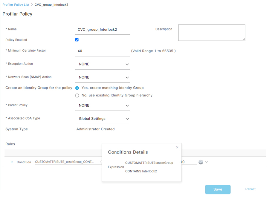
In this procedure, a custom Profiler Policy will be created for devices matching a specific Cyber Vision group.
-
Navigate to Work Centers > Profiler > Profiling Policies and click the Add button. The Profiler Policy page appears.
-
Complete the Profiler Policy form as follows:
-
Assign a name.
-
Chaeck the Policy Enabled check box
-
Assign a certainty factor.
-
Under Rules, from the Conditions drop-down list choose Create New Condition (Advance Option).
-
From the Expression drop-down list, choose Custom Attribute > assetGroup.
-
From the logic drop-down list, choose Contains.
-
In the text field, enter the Cyber Vision group value. In this example the Cyber Vision group name is Interlock2.
-
-
Enter the Certainty Factor value to be added if the Condition has been met.
-
-
Click Submit.

Note: follow the Integrating Cisco Cyber Vision with Cisco Identity Services Engine (ISE) via pxGrid document to use Cisco Cyber Vision attributes for ISE profiling.
Create Authentication and Authorization Policies on ISE
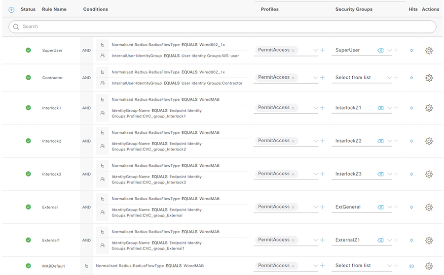
To configure the authorization policy in ISE, navigate to Policy > Policy Sets > Default and then choose Authorization Policy.
The following figure shows examples of authorization policies. The SuperUser rule (1) is an example of a policy that matches a user and assigns an SGT. The Interlock1 rule (2) is an example that matches an endpoint profile and assigns an SGT accordingly. The MABDefault rule (3) shows the default policy, which does not assign an SGT, so endpoints matching this rule will not override the default SGT assigned to the subnet of the Cell/Area zone.

Cyber Vision Sensor
The following template can be used to provision the industrial switch to prepare for Cisco Cyber Vision sensor installation. For actual sensor deployment refer to Cisco Cyber Vision documentation.
#if ($enable_iox == 1)

iox

#MODE_ENABLE

terminal shell

sleep 30

sleep 30

terminal no shell

#MODE_END_ENABLE

#end

vlan 2

remote-span

interface AppGigabitEthernet 1/1

switchport mode trunk

exit

monitor session 1 source interface $intRange

monitor session 1 destination remote vlan 2

monitor session 1 destination format-erspan 169.254.1.2 Feedback