Task Library for Smart Licensing Using Policy

This section is a grouping of tasks that apply to Smart Licensing Using Policy. It includes tasks performed on a product instance, on the CSLU interface, and on the CSSM Web UI.

To implement a particular topology, refer to the corresponding workflow to know the sequential order of tasks that apply. See .

To perform any additional configuration tasks, for instance, to configure a different license, or use an add-on license, or to configure a narrower reporting interval, refer to the corresponding task here. Check the "Supported Topologies" where provided, before you proceed.

RUM Reporting and Acknowledgment Requirement for Cisco Catalyst 9800-CL Wireless Controller

About This Requirement

Beginning with Cisco IOS XE Cupertino 17.7.1, if you are using a Cisco Catalyst 9800-CL Wireless Controller, you must complete RUM (Resource Utilization Measurement) reporting and ensure that the Acknowledgment (ACK) is made available on the product instance - at least once. This is to ensure that correct and up-to-date usage information is reflected in CSSM.

Prior to Cisco IOS XE Cupertino 17.7.1, RUM reporting and ACK installation was not mandatory for a Cisco Catalyst 9800-CL Wireless Controller (unlike other Cisco Catalyst Wireless Controllers).

This requirement is applicable to:

  • A new Cisco Catalyst 9800-CL Wireless Controller purchased through the Cisco Commerce portal or downloaded from the Software Download page, and where the software version running on the product instance is Cisco IOS XE Cupertino 17.7.1 or a later release.

  • An existing Cisco Catalyst 9800-CL Wireless Controller that is upgraded to Cisco IOS XE Cupertino 17.7.1 or later release.

Required Action to Meet This Requirement

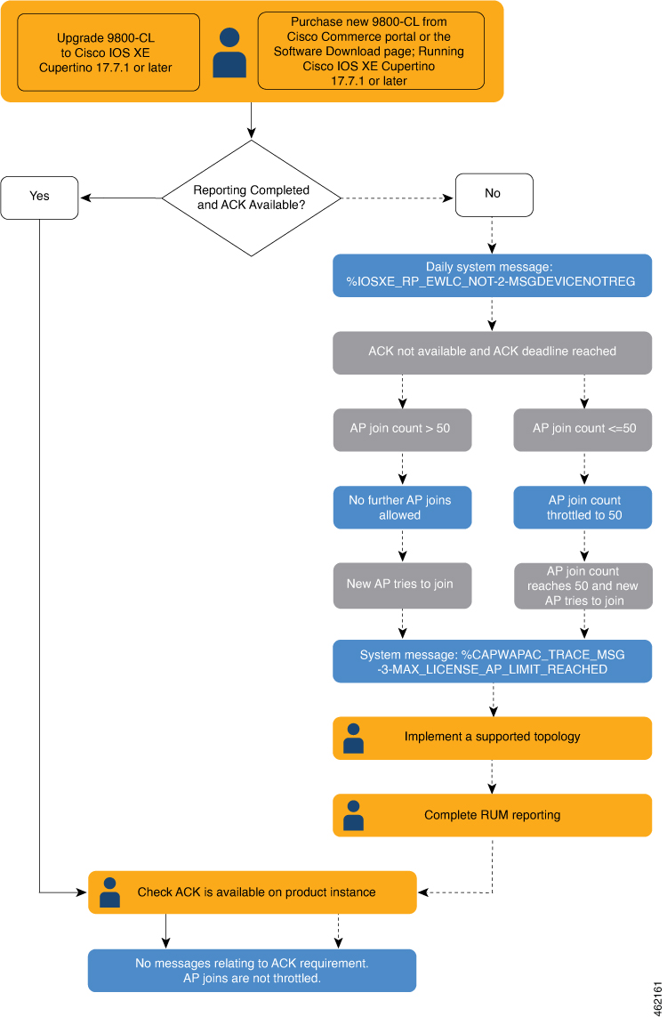
The following procedure provides information about what you have to do to ensure compliance with this requirement and avoid any throttling restrictions on new and upgraded product instances. This procedure is followed by a flow chart which depicts the same information.

  1. Check when the ACK is expected. Note system behavior if you don't meet the ACK deadline.

    Enter the show license air entities summary command in privileged EXEC mode and check field License Ack expected within.....................: [n] days.

    System behavior if you do not meet the ACK deadline:


    Note


    If the number of AP joins is greater than 10, the system displays this system message once-a-day until an ACK is installed: %IOSXE_RP_EWLC_NOT-2-MSGDEVICENOTREG.


    • If an ACK is not installed by the ACK deadline, and the count of currently active APs is lesser than or equal to 50, the system throttles the AP join count to 50.

    • If an ACK is not installed by the ACK deadline and the count of currently active APs is greater than 50, these currently active APs are not disconnected, but no new AP joins are allowed.

    • If there is a reload after the throttled state has come into effect, the system throttles the number of currently active APs to 50 when the system comes up after reload.

    • If there is a stateful switchover (SSO) after the throttled state has come into effect, all connected APs remain joined.

    • The following system message is displayed when the throttling restriction is effective and a new AP tries to join: %CAPWAPAC_TRACE_MSG-3-MAX_LICENSE_AP_LIMIT_REACHED.

    The AP join restriction and the display of the system messages continues until the first ACK is made available on the product instance.

  2. Implement a supported topology.

    If you have not already done so, implement one of the supported topologies and complete usage reporting. The method you use to send the RUM report to CSSM and ACK installation depends on the topology you implement.

    For more information, see: Connecting to Cisco SSM and Implementing Smart Licensing Using Policy.

  3. Ensure that the ACK is available on the product instance.

    In the output of the show license status command in privileged EXEC mode check for an updated timestamp in the Last ACK received:.
    Device# show license status
    <output truncated>
    Usage Reporting:
      Last ACK received: <none>
      Next ACK deadline: <none>
      Reporting push interval: 0 (no reporting)
      Next ACK push check: <none>
      Next report push: <none>
      Last report push: <none>
      Last report file write: <none>
    In the output of the show license air entities summary command in privileged EXEC mode, the License Ack expected within.....................: [n] days field is no longer displayed.
    Device# show license air entities summary
    Upcoming license report time....................: 21:05:16.092 UTC Mon Oct 25 2021
    No. of APs active at last report................: 57
    No. of APs newly added with last report.........: 57
    No. of APs deleted with last report.............: 0

    Once the first ACK is installed, the system messages ( %IOSXE_RP_EWLC_NOT-2-MSGDEVICENOTREG and %CAPWAPAC_TRACE_MSG-3-MAX_LICENSE_AP_LIMIT_REACHED) are not displayed any longer and AP join throttling restrictions are lifted.

    Figure 1. Flow Chart of System Events, User Actions, and System Actions on a Cisco Catalyst 9800-CL Wireless Controller

Logging into Cisco (CSLU Interface)

Depending on your needs, when working in CSLU, you can either be in connected or disconnected mode. To work in the connected mode, complete these steps to connect with Cisco.

Procedure


Step 1

From the CSLU Main screen, click Login to Cisco (located at the top right corner of the screen).

Step 2

Enter: CCO User Name and CCO Password.

Step 3

In the CSLU Preferences tab, check that the Cisco connectivity toggle displays “Cisco Is Available”.


Configuring a Smart Account and a Virtual Account (CSLU Interface)

Both the Smart Account and Virtual Account are configured through the Preferences tab. Complete the following steps to configure both Smart and Virtual Accounts for connecting to Cisco.

Procedure


Step 1

Select the Preferences Tab from the CSLU home screen.

Step 2

Perform these steps for adding both a Smart Account and Virtual Account:

  1. In the Preferences screen navigate to the Smart Account field and add the Smart Account Name.

  2. Next, navigate to the Virtual Account field and add the Virtual Account Name.

If you are connected to CSSM (In the Preferences tab, Cisco is Available), you can select from the list of available SA/VAs.

If you are not connected to CSSM (In the Preferences tab, Cisco Is Not Available), enter the SA/VAs manually.

Note


SA/VA names are case sensitive.

Step 3

Click Save. The SA/VA accounts are saved to the system

Only one SA/VA pair can reside on CSLU at a time. You cannot add multiple accounts. To change to another SA/VA pair, repeat Steps 2a and 2b then Save. A new SA/VA account pair replaces the previous saved pair


Adding a Product-Initiated Product Instance in CSLU (CSLU Interface)

Complete these steps to add a device-created Product Instance using the Preferences tab.

Procedure


Step 1

Select the Preferences tab.

Step 2

In the Preferences screen, de-select the Validate Device check box.

Step 3

Set the Default Connect Method to Product Instance Initiated and then click Save.


Ensuring Network Reachability for Product Instance-Initiated Communication

This task provides possible configurations that may be required to ensure network reachability for product instance-initiated communication. Steps marked as "(Required)" are required for all product instances, all other steps my be required or optional, depending the kind of product instance and network requirements. Configure the applicable commands:

Before you begin

Supported topologies: Connected to CSSM Through CSLU (product instance-initiated communication).

Procedure

  Command or Action Purpose

Step 1

enable

Example:

Device> enable

Enables privileged EXEC mode. Enter your password, if prompted.

Step 2

configure terminal

Example:

Device# configure terminal

Enters global configuration mode.

Step 3

interface interface-type-number

Example:

Device (config)# interface gigabitethernet0/0

Enters interface configuration mode and specifies the Ethernet interface, subinterface, or VLAN to be associated with the VRF.

Step 4

vrf forwarding vrf-name

Example:

Device(config-if)# vrf forwarding Mgmt-vrf

Associates the VRF with the Layer 3 interface. This command activates multiprotocol VRF on an interface

Step 5

ip address ip-address mask

Example:

Device(config-if)# ip address 192.168.0.1 
255.255.0.0

Defines the IP address for the VRF.

Step 6

negotiation auto

Example:

Device(config-if)# negotiation auto

Enables auto-negotiation operation for the speed and duplex parameters of an interface.

Note


Cisco Catalyst 9800-L-F Wireless Controller 10G Ports do not support in an auto-negotiation operation.

Step 7

end

Example:

Device(config-if)# end

Exits the interface configuration mode and enters global configuration mode.

Step 8

ip http client source-interface interface-type-number

Example:

Device(config)# ip http client 
source-interface gigabitethernet0/0

Configures a source interface for the HTTP client.

Step 9

ip route ip-address ip-mask subnet mask

Example:

Device(config)# ip route vrf mgmt-vrf 
192.168.0.1 255.255.0.0 192.168.255.1

(Required) Configures a route and gateway on the product instance. You can configure either a static route or a dynamic route.

Step 10

{ ip| ipv6} name-server server-address 1 ...server-address 6]

Example:

Device(config)# Device(config)# ip name-server 
vrf mgmt-vrf 173.37.137.85

Configures Domain Name System (DNS) on the VRF interface.

Step 11

ip domain lookup source-interface interface-type-number

Example:

Device(config)# ip domain lookup 
source-interface gigabitethernet0/0

Configures the source interface for the DNS domain lookup.

Step 12

ip domain name domain-name

Example:

Device(config)# ip domain name example.com

Configure DNS discovery of your domain. In accompanying example, the name-server creates entry cslu-local.example.com.

Adding a CSLU-Initiated Product Instance in CSLU (CSLU Interface)

Using the CSLU interface, you can configure the connect method to be CSLU Initiated. This connect method (mode) enables CSLU to retrieve Product Instance information from the Product Instance.


Note


The default Connect Method is set in the Preferences tab.

Complete these steps to add a Product Instance from the Inventory tab

Procedure


Step 1

Go to the Inventory tab and from the Product Instances table, select Add Single Product.

Step 2

Enter the Host (IP address of the Host).

Step 3

Select the Connect Method and select one of the CSLU Initiated connect methods.

Step 4

In the right panel, click Product Instance Login Credentials. The left panel of the screen changes to show the User Name and Password fields.

Step 5

Enter the product instance User Name and Password.

Step 6

Click Save.

The information is saved to the system and the device is listed in the Product Instances table with the Last Contact listed as never.


Collecting Usage Reports: CSLU Initiated (CSLU Interface)

CSLU also allows you to manually trigger the gathering of usage reports from devices.

After configuring and selecting a product instance (selecting Add Single Product, filling in the Host name and selecting a CSLU-initiated connect method), click Actions for Selected > Collect Usage. CSLU connects to the selected product instances and collects the usage reports. These usage reports are stored in CSLU’s local library. These reports can then be transferred to Cisco if CSLU is connected to Cisco, or (if you are not connected to Cisco) you can manually trigger usage collection by selecting Data > Export to CSSM.

If you are working in CSLU-initiated mode, complete these steps to configure CSLU to collect RUM reports from Product Instances.

Procedure


Step 1

Click the Preference tab and enter a valid Smart Account and Virtual Account, and then select an appropriate CSLU-initiated collect method. (If there have been any changes in Preferences, make sure you click Save).

Step 2

Click the Inventory tab and select one or more product instances.

Step 3

Click Actions for Selected > Collect Usage.

RUM reports are retrieved from each selected device and stored in the CSLU local library. The Last Contacted column is updated to show the time the report was received, and the Alerts column shows the status.

If CSLU is currently logged into Cisco the reports will be automatically sent to the associated Smart Account and Virtual Account in Cisco and Cisco will send an acknowledgement to CSLU as well as to the product instance. The acknowledgement will be listed in the alerts column of the Product Instance table. To manually transfer usage reports Cisco, from the CSLU main screen select Data > Export to CSSM.

Step 4

From the Export to CSSM modal, select the local directory where the reports are to be stored. (<CSLU_WORKING_Directory>/data/default/rum/unsent)

At this point, the usage reports are saved in your local directory (library). To upload these usage reports to Cisco, follow the steps described in .

Note


The Windows operating system can change the behavior of a usage report file properties by dropping the extension when that file is renamed. The behavior change happens when you rename the downloaded file and the renamed file drops the extension. For example, the downloaded default file named UD_xxx.tar is renamed to UD_yyy. The file loses its TAR extension and cannot function. To enable the usage file to function normally, after re-naming a usage report file, you must also add the TAR extension back to the file name, for example UD_yyy.tar.


Export to CSSM (CSLU Interface)

The Download All for Cisco menu option is a manual process used for offline purposes. Complete these steps to use the Download For Cisco menu option

Procedure


Step 1

Go to the Preferences tab, and turn off the Cisco Connectivity toggle switch.

The field switches to “Cisco Is Not Available”.

Step 2

From the main menu in the CSLU home screen navigate to Data > Export to CSSM.

Step 3

Select the file from the modal that opens and click Save. You now have the file saved.

Note


At this point you have a DLC file, RUM file, or both.

Step 4

Go to a station that has connectivity to Cisco, and complete the following:

Once the file is downloaded, you can import it into CSLU, see .


Import from CSSM (CSLU Interface)

Once you have received the ACK or other file (such as an authorization code) from Cisco, you are ready to Upload that file to your system. This procedure can be used for workstations that are offline. Complete these steps to select and upload files from Cisco.

Procedure


Step 1

Ensure that you have downloaded the file to a location that is accessible to CSLU.

Step 2

From the main menu in the CSLU home screen, navigate to Data > Import from CSSM.

Step 3

An Import from CSSM modal open for you to either:

  • Drag and Drop a file that resides on your local drive, or

  • Browse for the appropriate *.xml file, select the file and click Open.

If the upload is successful, you will get message indicating that the file was successfully sent to the server. If the upload is not successful, you will get an import error.

Step 4

When you have finished uploading, click the x at the top right corner of the modal to close it.


Ensuring Network Reachability for CSLU-Initiated Communication

This task provides possible configurations that may be required to ensure network reachability for CSLU-initiated communication. Steps marked as "(Required)" are required for all product instances, all other steps may be required or optional, depending the kind of product instance and network requirements. Configure the applicable commands:

Before you begin

Supported topologies: Connected to CSSM Through CSLU (CSLU-initiated communication).

Procedure

  Command or Action Purpose

Step 1

enable

Example:

Device> enable

Enables privileged EXEC mode. Enter your password, if prompted.

Step 2

configure terminal

Example:

Device# configure terminal

Enters global configuration mode.

Step 3

aaa new model

Example:

Device(config)# aaa new model

(Required) Enable the authentication, authorization, and accounting (AAA) access control model.

Step 4

aaa authentication login default local

Example:

Device(config)# aaa authentication login default local

(Required) Sets AAA authentication to use the local username database for authentication.

Step 5

aaa authorization exec default local

Example:

Device(config)# aaa authorization exec default local

Sets the parameters that restrict user access to a network. The user is allowed to run an EXEC shell.

Step 6

ip routing

Example:

Device(config)# ip routing

Enables IP routing.

Step 7

{ ip| ipv6} name-server server-address 1 ...server-address 6]

Example:

Device(config)# ip name-server vrf Mgmt-vrf 
192.168.1.100 192.168.1.200 192.168.1.300

(Optional) Specifies the address of one or more name servers to use for name and address resolution.

You can specify up to six name servers. Separate each server address with a space. The first server specified is the primary server. The device sends DNS queries to the primary server first. If that query fails, the backup servers are queried.

Step 8

ip domain lookup source-interface interface-type-number

Example:

Device(config)# ip domain lookup 
source-interface gigabitethernet0/0

Enables DNS-based hostname-to-address translation on your device. This feature is enabled by default.

If your network devices require connectivity with devices in networks for which you do not control name assignment, you can dynamically assign device names that uniquely identify your devices by using the global Internet naming scheme (DNS).

Step 9

ip domain name name

Example:

Device(config)# ip domain name vrf 
Mgmt-vrf cisco.com

Defines a default domain name that the software uses to complete unqualified hostnames (names without a dotted-decimal domain name).

Step 10

no username name

Example:

Device(config)# no username admin

(Required) Clears the specified username, if it exists. For name , enter the same username you will create in the next step. This ensures that a duplicate of the username you are going to create in the next step does not exist.

If you plan to use REST APIs for CSLU-initiated retrieval of RUM reports, you have to log in to CSLU. Duplicate usernames may cause the feature to work incorrectly if there are duplicate usernames in the system.

Step 11

username name privilege level password password

Example:

Device(config)# username admin privilege 15 
password 0 lab

(Required) Establishes a username-based authentication system.

The privilege keyword sets the privilege level for the user. A number between 0 and 15 that specifies the privilege level for the user.

The password allows access to the name argument. A password must be from 1 to 25 characters, can contain embedded spaces, and must be the last option specified in the username command.

This enables CSLU to use the product instance native REST.

Note


Enter this username and password in CSLU (Step 4. f. CSLU can then collect RUM reports from the product instance.

Step 12

interface interface-type-number

Example:

Device (config)# interface gigabitethernet0/0

Enters interface configuration mode and specifies the Ethernet interface, subinterface, or VLAN to be associated with the VRF.

Step 13

vrf forwarding vrf-name

Example:

Device(config-if)# vrf forwarding Mgmt-vrf

Associates the VRF with the Layer 3 interface. This command activates multiprotocol VRF on an interface

Step 14

ip address ip-address mask

Example:

Device(config-if)# ip address 192.168.0.1 255.255.0.0

Defines the IP address for the VRF.

Step 15

negotiation auto

Example:

Device(config-if)# negotiation auto

Enables auto-negotiation operation for the speed and duplex parameters of an interface.

Step 16

no shutdown

Example:

Device(config-if)# no shutdown

Restarts a disabled interface.

Step 17

end

Example:

Device(config-if)# end

Exits the interface configuration mode and enters global configuration mode.

Step 18

ip http server

Example:

Device(config)# ip http server

(Required) Enables the HTTP server on your IP or IPv6 system, including a Cisco web browser user interface. The HTTP server uses the standard port 80, by default.

Step 19

ip http authentication local

Example:

ip http authentication local
Device(config)# 

(Required) Specifies a particular authentication method for HTTP server users.

The local keyword means that the login user name, password and privilege level access combination specified in the local system configuration (by the username global configuration command) should be used for authentication and authorization.

Step 20

ip http secure-server

Example:

Device(config)# ip http server

(Required) Enables a secure HTTP (HTTPS) server. The HTTPS server uses the Secure Sockets Layer (SSL) version 3.0 protocol.

Step 21

ip http max-connections

Example:

Device(config)# ip http max-connections 16

(Required) Configures the maximum number of concurrent connections allowed for the HTTP server. Enter an integer in the range from 1 to 16. The default is 5.

Step 22

ip tftp source-interface interface-type-number

Example:

Device(config)# ip tftp source-interface 
GigabitEthernet0/0

Specifies the IP address of an interface as the source address for TFTP connections.

Step 23

ip route ip-address ip-mask subnet mask

Example:

Device(config)# ip route vrf mgmt-vrf 
192.168.0.1 255.255.0.0 192.168.255.1

Configures a route and gateway on the product instance. You can configure either a static route or a dynamic route.

Step 24

logging host

Example:

Device(config)# logging host 172.25.33.20 
vrf Mgmt-vrf

Logs system messages and debug output to a remote host.

Step 25

end

Example:

Device(config)# end

Exits the global configuration mode and enters privileged EXEC mode.

Step 26

show ip http server session-module

Example:

Device# show ip http server session-module

(Required) Verifies HTTP connectivity. In the output, check that SL_HTTP is active. Additionally, you can also perform the following checks :

  • From device where CSLU is installed, verify that you can ping the product instance. A successful ping confirms that the product instance is reachable.

  • From a Web browser on the device where CSLU is installed verify https://<product-instance-ip>/. This ensures that the REST API from CSLU to the product instance works as expected.

Assigning a Smart Account and Virtual Account (SSM On-Prem UI)

You can use this procedure to import one or more product instances along with corresponding Smart Account and Virtual Account information, into the SSM On-Prem database. This enables SSM On-Prem to map product instances that are part of local virtual accounts (other than the default local virtual account), to the correct license pool in CSSM:

Before you begin

Supported topologies: SSM On-Prem Deployment (product instance-initiated communication).

Procedure


Step 1

Log into the SSM On-Prem and select the Smart Licensing workspace.

Step 2

Navigate to Inventory > SL Using Policy > Export/Import All > Import Product Instances List

The Upload Product Instances window is displayed.

Step 3

Click Download to download the .csv template file and enter the required information for all the product instances in the template.

Step 4

Once you have filled-out the template, click Inventory > SL Using Policy > Export/Import All > Import Product Instances List.

The Upload Product Instances window is displayed.

Step 5

Now, click Browse and upload the filled-out .csv template.

Smart Account and Virtual Account information for all uploaded product instances is now available in SSM On-Prem.


Validating Devices (SSM On-Prem UI)

When device validation is enabled, RUM reports from an unknown product instance (not in the SSM On-Prem database) are rejected.

By default, devices are not validated. Complete the following steps to enable it:

Before you begin

Supported topologies: SSM On-Prem Deployment (product instance-initiated communication).

Procedure


Step 1

In the On-Prem License Workspace window, click Admin Workspace and log in, if prompted.

The On-Prem Admin Workspace window is displayed.

Step 2

Click the Settings widget.

The Settings window is displayed.

Step 3

Navigate to the CSLU tab and turn-on the Validate Device toggle switch.

RUM reports from an unknown product instance will now be rejected. If you haven't already, you must now add the required product instances to the SSM On-Prem database before sending RUM reports. See Assigning a Smart Account and Virtual Account (SSM On-Prem UI)


Ensuring Network Reachability for Product Instance-Initiated Communication

This task provides possible configurations that may be required to ensure network reachability for product instance-initiated communication. Steps marked as "(Required)" are required for all product instances, all other steps my be required or optional, depending the kind of product instance and network requirements. Configure the applicable commands:


Note


Ensure that you configure steps 13, 14, and 15 exactly as shown below. These commands must be configured to ensure that the correct trustpoint is used and that the necessary certificates are accepted for network reachability.


Before you begin

Supported topologies: SSM On-Prem Deployment(product instance-initiated communication).

Procedure

  Command or Action Purpose

Step 1

enable

Example:

Device> enable

Enables privileged EXEC mode. Enter your password, if prompted.

Step 2

configure terminal

Example:

Device# configure terminal

Enters global configuration mode.

Step 3

interface interface-type-number

Example:

Device (config)# interface gigabitethernet0/0

Enters interface configuration mode and specifies the Ethernet interface, subinterface, or VLAN to be associated with the VRF.

Step 4

vrf forwarding vrf-name

Example:

Device(config-if)# vrf forwarding Mgmt-vrf

Associates the VRF with the Layer 3 interface. This command activates multiprotocol VRF on an interface

Step 5

ip address ip-address mask

Example:

Device(config-if)# ip address 192.168.0.1 
255.255.0.0

Defines the IP address for the VRF.

Step 6

negotiation auto

Example:

Device(config-if)# negotiation auto

Enables auto-negotiation operation for the speed and duplex parameters of an interface.

Step 7

end

Example:

Device(config-if)# end

Exits the interface configuration mode and enters global configuration mode.

Step 8

ip http client source-interface interface-type-number

Example:

Device(config)# ip http client 
source-interface gigabitethernet0/0

Configures a source interface for the HTTP client.

Step 9

ip route ip-address ip-mask subnet mask

Example:

Device(config)# ip route vrf mgmt-vrf 
192.168.0.1 255.255.0.0 192.168.255.1

(Required) Configures a route and gateway on the product instance. You can configure either a static route or a dynamic route.

Step 10

{ ip| ipv6} name-server server-address 1 ...server-address 6]

Example:

Device(config)# Device(config)# ip name-server 
vrf mgmt-vrf 198.51.100.1

Configures Domain Name System (DNS) on the VRF interface.

Step 11

ip domain lookup source-interface interface-type-number

Example:

Device(config)# ip domain lookup 
source-interface gigabitethernet0/0

Configures the source interface for the DNS domain lookup.

Step 12

ip domain name domain-name

Example:

Device(config)# ip domain name example.com

Configure DNS discovery of your domain. In the accompanying example, the name-server creates entry cslu-local.example.com.

Step 13

crypto pki trustpoint SLA-TrustPoint

Example:

Device(config)# crypto pki trustpoint SLA-TrustPoint
Device(ca-trustpoint)#

(Required) Declares that the product instance should use trustpoint “SLA-TrustPoint” and enters the ca-trustpoint configuration mode. The product instance does not recognize any trustpoints until you declare a trustpoint using this command.

Step 14

enrollment terminal

Example:

Device(ca-trustpoint)# enrollment terminal

Required) Specifies the certificate enrollment method.

Step 15

revocation-check none

Example:

Device(ca-trustpoint)# revocation-check none

(Required) Specifies a method that is to be used to ensure that the certificate of a peer is not revoked. For the SSM On-Prem Deployment topology, enter the none keyword. This means that a revocation check will not be performed and the certificate will always be accepted.

Step 16

exit

Example:

Device(ca-trustpoint)# exit
Device(config)# exit

Exits the ca-trustpoint configuration mode and then the global configuration mode and returns to privileged EXEC mode.

Step 17

copy running-config startup-config

Example:

Device# copy running-config startup-config

Saves your entries in the configuration file.

Retrieving the Transport URL (SSM On-Prem UI)

You must configure the transport URL on the product instance when you deploy the product instance-initiated communication with SSM On-Prem deployment. This task show you how to easily copy the complete URL including the tenant ID from SSM On-Prem.

Before you begin

Supported topologies: SSM On-Prem Deployment (product instance-initiated communication).

Procedure


Step 1

Log into SSM On-Prem and select the Smart Licensing workspace.

Step 2

Navigate to the Inventory tab and from the dropdown list of local virtual accounts (top right corner), select the default local virtual account. When you do, the area under the Inventory tab displays Local Virtual Account: Default.

Step 3

Navigate to the General tab.

The Product Instance Registration Tokens area is displayed.

Step 4

In the Product Instance Registration Tokens area click CSLU Transport URL.

The Product Registration URL pop-window is displayed.

Step 5

Copy the entire URL and save it in an accessible place.

You will require the URL when you configure the transport type and URL on the product instance.

Step 6

Configure the transport type and URL. See: Setting the Transport Type, URL, and Reporting Interval.


Exporting and Importing Usage Data (SSM On-Prem UI)

You can use this procedure to complete usage synchronization between SSM On-Prem and CSSM when SSM On-Prem is disconnected from CSSM.

Before you begin

Supported topologies:

  • SSM On-Prem Deployment (SSM On-Prem-initiated communication)

  • SSM On-Prem Deployment (product instance-initiated communication).

Reporting data must be available in SSM On-Prem. You must have either pushed the necessary reporting data from the product instance to SSM On-Prem (product instance-initiated communication) or retrieved the necessary reporting data from the product instance (SSM On-Prem-initiated communication).

Procedure


Step 1

Log into SSM On-Prem and select Smart Licensing.

Step 2

Navigate to Inventory > SL Using Policy tab.

Step 3

In the SL Using Policy tab area, click Export/Import All... > Export Usage to Cisco.

This generates one .tar file with all the usage reports available in the SSM On-Prem server.

Step 4

Complete this task in CSSM: .

At the end of this task you will have an ACK file to import into SSM On-Prem.

Step 5

Again navigate to the Inventory > SL Using Policy tab.

Step 6

In the SL Using Policy tab area, click Export/Import All... > Import From Cisco . Upload the .tar ACK file.

To verify ACK import, in the SL Using Policy tab area check the Alerts column of the corresponding product instance. The following message is displayed: Acknowledgement received from CSSM.


Adding One or More Product Instances (SSM On-Prem UI)

You can use this procedure to add one product instance or to import and add multiple product instances. It enables SSM On-Prem to retrieve information from the product instance.

Before you begin

Supported topologies: SSM On-Prem Deployment (SSM On-Prem-initiated communication).

Procedure


Step 1

Log into the SSM On-Prem UI and click Smart Licensing.

Step 2

Navigate to Inventory tab. Select a local virtual account from the drop-down list in the top right corner.

Step 3

Navigate to the SL Using Policy tab.

Step 4

Add a single product or import multiple product instances (choose one).

  • To add a single product instance:
    1. In the SL Using Policy tab area, click Add Single Product.

    2. In the Host field, enter the IP address of the host (product instance).

    3. From the Connect Method dropdown list, select an appropriate SSM On-Prem-initiated connect method.

      The available connect methods for SSM On-Prem-initiated communication are: NETCONF, RESTCONF, and REST API.

    4. In the right panel, click Product Instance Login Credentials.

      The Product Instance Login Credentials window is displayed

      Note


      You need the login credentials only if a product instance requires a SLAC.

    5. Enter the User ID and Password, and click Save.

      This is the same user ID and password that you configured as part of commands required to establish network reachability (Ensuring Network Reachability for SSM On-Prem-Initiated Communication).

      Once validated, the product instance is displayed in the listing in the SL Using Policy tab area.

  • To import multiple product instances:
    1. In SL Using Policy tab, click Export/Import All... > Import Product Instances List.

      The Upload Product Instances window is displayed.

    2. Click Download to download the predefined .csv template.

    3. Enter the required information for all the product instances in the .csv template.

      In the template, ensure that you provide Host, Connect Method and Login Credentials for all product instances.

      The available connect methods for SSM On-Prem-initiated communication are: NETCONF, RESTCONF, and REST API.

      Login credentials refer to the user ID and password that you configured as part of commands required to establish network reachability (Ensuring Network Reachability for SSM On-Prem-Initiated Communication).

    4. Again navigate to Inventory > SL Using Policy tab. Click Export/Import All.... > Import Product Instances List.

      The Upload Product Instances window is displayed.

    5. Now upload the filled-out .csv template.

      Once validated, the product instances are displayed in the listing in the SL Using Policy tab.


Ensuring Network Reachability for SSM On-Prem-Initiated Communication

This task provides possible configurations that may be required to ensure network reachability for SSM On-Prem-initiated communication. Steps marked as "(Required)" are required for all product instances, all other steps may be required or optional, depending the kind of product instance and network requirements. Configure the applicable commands:


Note


Ensure that you configure steps 25, 26, and 27 exactly as shown below. These commands must be configured to ensure that the correct trustpoint is used and that the necessary certificates are accepted for network reachability.


Before you begin

Supported topologies: SSM On-Prem Deployment (SSM On-Prem-initiated communication).

Procedure

  Command or Action Purpose

Step 1

enable

Example:

Device> enable

Enables privileged EXEC mode. Enter your password, if prompted.

Step 2

configure terminal

Example:

Device# configure terminal

Enters global configuration mode.

Step 3

aaa new model

Example:

Device(config)# aaa new model

(Required) Enable the authentication, authorization, and accounting (AAA) access control model.

Step 4

aaa authentication login default local

Example:

Device(config)# aaa authentication login default local

(Required) Sets AAA authentication to use the local username database for authentication.

Step 5

aaa authorization exec default local

Example:

Device(config)# aaa authorization exec default local

Sets the parameters that restrict user access to a network. The user is allowed to run an EXEC shell.

Step 6

ip routing

Example:

Device(config)# ip routing

Enables IP routing.

Step 7

{ ip| ipv6} name-server server-address 1 ...server-address 6]

Example:

Device(config)# ip name-server vrf Mgmt-vrf 
192.168.1.100 192.168.1.200 192.168.1.300

(Optional) Specifies the address of one or more name servers to use for name and address resolution.

You can specify up to six name servers. Separate each server address with a space. The first server specified is the primary server. The device sends DNS queries to the primary server first. If that query fails, the backup servers are queried.

Step 8

ip domain lookup source-interface interface-type-number

Example:

Device(config)# ip domain lookup 
source-interface gigabitethernet0/0

Enables DNS-based hostname-to-address translation on your device. This feature is enabled by default.

If your network devices require connectivity with devices in networks for which you do not control name assignment, you can dynamically assign device names that uniquely identify your devices by using the global Internet naming scheme (DNS).

Step 9

ip domain name name

Example:

Device(config)# ip domain name vrf 
Mgmt-vrf cisco.com

Defines a default domain name that the software uses to complete unqualified hostnames (names without a dotted-decimal domain name).

Step 10

no username name

Example:

Device(config)# no username admin

(Required) Clears the specified username, if it exists. For name , enter the same username you will create in the next step. This ensures that a duplicate of the username you are going to create in the next step does not exist.

If you plan to use REST APIs for SSM On-Prem-initiated retrieval of RUM reports, you have to log in to SSM On-Prem. Duplicate usernames may cause the feature to work incorrectly if there are present in the system.

Step 11

username name privilege level password password

Example:

Device(config)# username admin privilege 15 
password 0 lab

(Required) Establishes a username-based authentication system.

The privilege keyword sets the privilege level for the user. A number between 0 and 15 that specifies the privilege level for the user.

The password allows access to the name argument. A password must be from 1 to 25 characters, can contain embedded spaces, and must be the last option specified in the username command.

This enables SSM On-Prem to use the product instance native REST.

Note


Enter this username and password in SSM On-Prem (Adding One or More Product Instances (SSM On-Prem UI)). This enables SSM On-Prem to collect RUM reports from the product instance.

Step 12

interface interface-type-number

Example:

Device (config)# interface gigabitethernet0/0

Enters interface configuration mode and specifies the Ethernet interface, subinterface, or VLAN to be associated with the VRF.

Step 13

vrf forwarding vrf-name

Example:

Device(config-if)# vrf forwarding Mgmt-vrf

Associates the VRF with the Layer 3 interface. This command activates multiprotocol VRF on an interface

Step 14

ip address ip-address mask

Example:

Device(config-if)# ip address 192.168.0.1 255.255.0.0

Defines the IP address for the VRF.

Step 15

negotiation auto

Example:

Device(config-if)# negotiation auto

Enables auto-negotiation operation for the speed and duplex parameters of an interface.

Step 16

no shutdown

Example:

Device(config-if)# no shutdown

Restarts a disabled interface.

Step 17

end

Example:

Device(config-if)# end

Exits the interface configuration mode and enters global configuration mode.

Step 18

ip http server

Example:

Device(config)# ip http server

(Required) Enables the HTTP server on your IP or IPv6 system, including a Cisco web browser user interface. The HTTP server uses the standard port 80, by default.

Step 19

ip http authentication local

Example:

ip http authentication local
Device(config)# 

(Required) Specifies a particular authentication method for HTTP server users.

The local keyword means that the login user name, password and privilege level access combination specified in the local system configuration (by the username global configuration command) should be used for authentication and authorization.

Step 20

ip http secure-server

Example:

Device(config)# ip http server

(Required) Enables a secure HTTP (HTTPS) server. The HTTPS server uses the Secure Sockets Layer (SSL) version 3.0 protocol.

Step 21

ip http max-connections

Example:

Device(config)# ip http max-connections 16

(Required) Configures the maximum number of concurrent connections allowed for the HTTP server. Enter an integer in the range from 1 to 16. The default is 5.

Step 22

ip tftp source-interface interface-type-number

Example:

Device(config)# ip tftp source-interface 
GigabitEthernet0/0

Specifies the IP address of an interface as the source address for TFTP connections.

Step 23

ip route ip-address ip-mask subnet mask

Example:

Device(config)# ip route vrf mgmt-vrf 
192.168.0.1 255.255.0.0 192.168.255.1

Configures a route and gateway on the product instance. You can configure either a static route or a dynamic route.

Step 24

logging host

Example:

Device(config)# logging host 172.25.33.20 
vrf Mgmt-vrf

Logs system messages and debug output to a remote host.

Step 25

crypto pki trustpoint SLA-TrustPoint

Example:

Device(config)# crypto pki trustpoint SLA-TrustPoint
Device(ca-trustpoint)#

(Required) Declares that the product instance should use trustpoint “SLA-TrustPoint” and enters the ca-trustpoint configuration mode. The product instance does not recognize any trustpoints until you declare a trustpoint using this command.

Step 26

enrollment terminal

Example:

Device(ca-trustpoint)# enrollment terminal

Required) Specifies the certificate enrollment method.

Step 27

revocation-check none

Example:

Device(ca-trustpoint)# revocation-check none

(Required) Specifies a method that is to be used to ensure that the certificate of a peer is not revoked. For the SSM On-Prem Deployment topology, enter the none keyword. This means that a revocation check will not be performed and the certificate will always be accepted.

Step 28

end

Example:

Device(ca-trustpoint)# exit
Device(config)# end

Exits the ca-trustpoint configuration mode and then the global configuration mode and returns to privileged EXEC mode.

Step 29

show ip http server session-module

Example:

Device# show ip http server session-module

(Required) Verifies HTTP connectivity. In the output, check that SL_HTTP is active. Additionally, you can also perform the following checks :

  • From device where SSM On-Prem is installed, verify that you can ping the product instance. A successful ping confirms that the product instance is reachable.

  • From a Web browser on the device where SSM On-Prem is installed verify https://<product-instance-ip>/. This ensures that the REST API from SSM On-Prem to the product instance works as expected.

Step 30

copy running-config startup-config

Example:

Device# copy running-config startup-config

Saves your entries in the configuration file.

Setting Up a Connection to CSSM

The following steps show how to set up a Layer 3 connection to CSSM to verify network reachability. Steps marked as "(Required)" are required for all product instances, all other steps may be required or optional, depending the kind of product instance and network requirements. Configure the applicable commands:

Procedure

  Command or Action Purpose

Step 1

enable

Example:

Device> enable

Enables privileged EXEC mode. Enter your password, if prompted.

Step 2

configure terminal

Example:

Device# configure terminal

Enters global configuration mode.

Step 3

{ ip| ipv6} name-server server-address 1 ...server-address 6]

Example:

Device(config)# ip name-server 
209.165.201.1 209.165.200.225 209.165.201.14 209.165.200.230

Specifies the address of one or more name servers to use for name and address resolution.

You can specify up to six name servers. Separate each server address with a space. The first server specified is the primary server. The device sends DNS queries to the primary server first. If that query fails, the backup servers are queried.

Step 4

ip name-server vrf Mgmt-vrf server-address 1...server-address 6

Example:

Device(config)# ip name-server vrf Mgmt-vrf 
209.165.201.1 209.165.200.225 209.165.201.14 209.165.200.230

(Optional) Configures DNS on the VRF interface. You can specify up to six name servers. Separate each server address with a space.

Note


This command is an alternative to the ip name-server command.

Step 5

ip domain lookup source-interface interface-type interface-number

Example:

Device(config)# ip domain lookup source-interface Vlan100

Configures the source interface for the DNS domain lookup.

Step 6

ip domain name domain-name

Example:

Device(config)# ip domain name example.com

Configures the domain name.

Step 7

ip host tools.cisco.com ip-address

Example:

Device(config)# ip host tools.cisco.com 209.165.201.30

Configures static hostname-to-address mappings in the DNS hostname cache if automatic DNS mapping is not available.

Step 8

interface interface-type-number

Example:

Device(config)# interface Vlan100
Device(config-if)# ip address 192.0.2.10 255.255.255.0
Device(config-if)# exit

Configures a Layer 3 interface. Enter an interface type and number or a VLAN.

Step 9

ntp server ip-address [version number] [key key-id] [prefer]

Example:

Device(config)# ntp server 198.51.100.100 version 2 prefer

(Required) Activates the NTP service (if it has not already been activated) and enables the system to synchronize the system software clock with the specified NTP server. This ensures that the device time is synchronized with CSSM.

Use the prefer keyword if you need to use this command multiple times and you want to set a preferred server. Using this keyword reduces switching between servers.

Step 10

switchport access vlan vlan_id

Example:

Device(config)# interface GigabitEthernet1/0/1
Device(config-if)# switchport access vlan 100
Device(config-if)# switchport mode access
Device(config-if)# exit
OR
Device(config)# 

Enables the VLAN for which this access port carries traffic and sets the interface as a nontrunking nontagged single-VLAN Ethernet interface.

Note


This step is to be configured only if the switchport access mode is required. The switchport access vlan command may apply to Catalyst switching product instances, for example, and for routing product instances you may want to configure the ip address ip-address mask command instead.

Step 11

ip route ip-address ip-mask subnet mask

Example:

Device(config)# ip route 192.0.2.0 255.255.255.255 192.0.2.1

Configures a route on the device. You can configure either a static route or a dynamic route.

Step 12

ip http client source-interface interface-type-number

Example:

Device(config)# ip http client source-interface Vlan100

(Required) Configures a source interface for the HTTP client. Enter an interface type and number or a VLAN.

Step 13

exit

Example:

Device(config)# exit

Exits global configuration mode and returns to privileged EXEC mode.

Step 14

copy running-config startup-config

Example:

Device# copy running-config startup-config

Saves your entries in the configuration file.

Configuring Smart Transport Through an HTTPs Proxy

To use a proxy server to communicate with CSSM when using the Smart transport mode, complete the following steps:

Procedure

  Command or Action Purpose

Step 1

enable

Example:

Device> enable

Enables privileged EXEC mode. Enter your password, if prompted.

Step 2

configure terminal

Example:

Device# configure terminal

Enters global configuration mode.

Step 3

license smart transport smart

Example:

Device(config)# license smart transport smart

Enables Smart transport mode.

Step 4

license smart url default

Example:

Device(config)# license smart transport default

Automatically configures the Smart URL (https://smartreceiver.cisco.com/licservice/license). For this option to work as expected, the transport mode in the previous step must be configured as smart.

Step 5

license smart proxy { address address_hostname| port port_num}

Example:

Device(config)# license smart proxy address 192.168.0.1
Device(config)# license smart proxy port 3128

Configures a proxy for the Smart transport mode. When a proxy is configured, licensing messages are sent to the proxy along with the final destination URL (CSSM). The proxy sends the message on to CSSM. Configure the proxy address and port number separately:

  • address address_hostname : Specifies the proxy address. Enter the IP address or hostname of the proxy server.

  • port port_num : Specifies the proxy port. Enter the proxy port number.

Note the change in the criteria for the acceptance of proxy servers, starting with Cisco IOS XE Bengaluru 17.6.1: only the status code of the proxy server response is verified by the system and not the reason phrase. The RFC format is status-line = HTTP-version SP status-code SP reason-phrase CRLF. For more information about the status line, see section 3.1.2 of RFC 7230.

Configuring the Call Home Service for Direct Cloud Access

The Call Home service provides email-based and web-based notification of critical system events to CSSM. To configure the transport mode, enable the Call Home service, and configure a destination profile (A destination profile contains the required delivery information for an alert notification. At least one destination profile is required.), complete the following steps:


Note


All steps are required unless specifically called-out as “(Optional)”.


Procedure

  Command or Action Purpose

Step 1

enable

Example:

Device> enable

Enables privileged EXEC mode. Enter your password, if prompted.

Step 2

configure terminal

Example:

Device# configure terminal

Enters global configuration mode.

Step 3

license smart transport callhome

Example:

Device(config)# license smart transport callhome

Enables Call Home as the transport mode.

Step 4

license smart url url

Example:

Device(config)# license smart url 
https://tools.cisco.com/its/service/oddce/services/DDCEService

For the callhome transport mode, configure the CSSM URL exactly as shown in the example.

Step 5

service call-home

Example:

Device(config)# service call-home

Enables the Call Home feature.

Step 6

call-home

Example:

Device(config)# call-home

Enters Call Home configuration mode.

Step 7

no http secure server-identity-check

Example:

Device(config-call-home)# no http secure 
server-identity-check

Disables server identity check when HTTP connection is established.

Step 8

contact-email-address email-address

Example:

Device(config-call-home)# contact-email-addr
username@example.com

Assigns customer's email address and enables Smart Call Home service full reporting capability and sends a full inventory message from Call-Home TAC profile to Smart Call Home server to start full registration process. You can enter up to 200 characters in email address format with no spaces.

Step 9

profile name

Example:

Device(config-call-home)# profile CiscoTAC-1
Device(config-call-home-profile)#

Enters the Call Home destination profile configuration submode for the specified destination profile.

By default:

  • The CiscoTAC-1 profile is inactive. To use this profile with the Call Home service, you must enable the profile.

  • The CiscoTAC-1 profile sends a full report of all types of events subscribed in the profile. The alternative is to additionally configure Device(cfg-call-home-profile)# anonymous-reporting-only anonymous-reporting-only. When this is set, only crash, inventory, and test messages will be sent.

Use the show call-home profile all command to check the profile status.

Step 10

active

Example:

Device(config-call-home-profile)# active

Enables the destination profile.

Step 11

destination transport-method http{email |http}

Example:

Device(config-call-home-profile)# destination transport-method 
http
AND
Device(config-call-home-profile)# no destination transport-method
 email

Enables the message transport method. In the example, Call Home service is enabled via HTTP and transport via email is disabled.

The no form of the command disables the method.

Step 12

destination address { email email_address |http url}

Example:

Device(config-call-home-profile)# destination address http 
https://tools.cisco.com/its/service/oddce/services/DDCEService
AND
Device(config-call-home-profile)# no destination address http 
https://tools.cisco.com/its/service/oddce/services/DDCEService

Configures the destination e-mail address or URL to which Call Home messages are sent. When entering a destination URL, include either http:// (default) or https://, depending on whether the server is a secure server.

In the example provided here, a http:// destination URL is configured; and the no form of the command is configured for https://.

Step 13

exit

Example:

Device(config-call-home-profile)# exit

Exits Call Home destination profile configuration mode and returns to Call Home configuration mode.

Step 14

exit

Example:

Device(config-call-home)# end

Exits Call Home configuration mode and returns to privileged EXEC mode.

Step 15

copy running-config startup-config

Example:

Device# copy running-config startup-config

Saves your entries in the configuration file.

Step 16

show call-home profile {name |all}

Displays the destination profile configuration for the specified profile or all configured profiles.

Configuring the Call Home Service for Direct Cloud Access through an HTTPs Proxy Server

The Call Home service can be configured through an HTTPs proxy server. This configuration requires no user authentication to connect to CSSM.


Note


Authenticated HTTPs proxy configurations are not supported.


To configure and enable the Call Home service through an HTTPs proxy, complete the following steps:


Note


All steps are required unless specifically called-out as “(Optional)”.


Procedure

  Command or Action Purpose

Step 1

enable

Example:

Device> enable

Enables privileged EXEC mode. Enter your password, if prompted.

Step 2

configure terminal

Example:

Device# configure terminal

Enters global configuration mode.

Step 3

license smart transport callhome

Example:

Device(config)# license smart transport callhome

Enables Call Home as the transport mode.

Step 4

service call-home

Example:

Device(config)# service call-home

Enables the Call Home feature.

Step 5

call-home

Example:

Device(config)# call-home

Enters Call Home configuration mode.

Step 6

http-proxy proxy-address proxy-port port-number

Example:

Device(config-call-home)# http-proxy 198.51.100.10 port 5000

Configures the proxy server information to the Call Home service.

Note the change in the criteria for the acceptance of proxy servers, starting with Cisco IOS XE Bengaluru 17.6.1: only the status code of the proxy server response is verified by the system and not the reason phrase. The RFC format is status-line = HTTP-version SP status-code SP reason-phrase CRLF. For more information about the status line, see section 3.1.2 of RFC 7230.

Step 7

exit

Example:

Device(config-call-home)# exit

Exits Call Home configuration mode and enters global configuration mode.

Step 8

exit

Example:

Device(config)# exit

Exits global configuration mode and enters privileged EXEC mode.

Step 9

copy running-config startup-config

Example:

Device# copy running-config startup-config

Saves your entries in the configuration file.

Removing and Returning an Authorization Code

To remove and return an SLR authorization code, complete the following steps.

Before you begin

Supported topologies: all

Procedure

  Command or Action Purpose

Step 1

enable

Example:

Device> enable

Enables privileged EXEC mode. Enter your password, if prompted.

Step 2

show license summary

Example:

Device# show license summary

Ensure that the license that you want to remove and return is not in-use. If it is in-use, you must first disable the feature.

Step 3

license smart authorization return{ all| local} { offline[ path] | online}

Example:

Device# license smart authorization return all online

Enter this return code in Cisco Smart Software Manager portal:
UDI: PID:C9800-CL-K9,SN:93BBAH93MGS
    Return code: CqaUPW-WSPYiq-ZNU2ci-SnWydS-hBCXHP-MuyPqy-
PJ1GiG-tPTGQj-S2h
UDI: PID:C9800-CL-K9,SN:9XECPSUU4XN
    Return code: CNLwxR-eWiAEJ-XaTEQg-j4rrYW-dSRz9j-37VpcP-
imjuLD-mNeA4k-TXA

OR

Device# license smart authorization return local offline
Enter this return code in Cisco Smart Software Manager 
portal: 
UDI: PID:C9800-CL-K9,SN:93BBAH93MGS
    Return code: CqaUPW-WSPYiq-ZNU2ci-SnWydS-hBCXHP-MuyPqy-
PJ1GiG-tPTGQj-S2h
UDI: PID:C9800-CL-K9,SN:9XECPSUU4XN
    Return code: CNLwxR-eWiAEJ-XaTEQg-j4rrYW-dSRz9j-37VpcP-
imjuLD-mNeA4k-TXA

OR

Device# license smart authorization return local offline 
bootflash:return-code.txt

Returns an authorization code back to the license pool in CSSM. A return code is displayed after you enter this command.

Specify the product instance:

  • all: Performs the action for all connected product instances in a High Availability set-up.

  • local: Performs the action for the active product instance. This is the default option.

Specify if you are connected to CSSM or not:

  • If connected to CSSM, enter online . The code is automatically returned to CSSM and a confirmation is returned and installed on the product instance. If you choose this option, the return code is automatically submitted to CSSM.

  • If not connected to CSSM, enter offline[path] .

    If you enter only the offline keyword, you must copy the return code that is displayed on the CLI and enter it in CSSM.

    If you specify a file name and path, the return code is saved in the specified location. The file format can be any readable format. For example: Device# license smart authorization return local offline bootflash:return-code.txt.

    For software versions Cisco IOS XE Cupertino 17.7.1 and later only: After you save the return request in a file, you can upload the file to CSSM in the same location and in the same way as you upload a RUM report: .

    To enter the return code in CSSM, complete this task: Removing the Product Instance from CSSM. Proceed with the next step only after you complete this step.

Step 4

configure terminal

Example:

Device# configure terminal

Enters the global configuration mode.

Step 5

no license smart reservation

Example:

Device(config)# no license smart reservation

Disables SLR configuration on the product instance.

You must complete the authorization code return process in Step 3 above - whether online or offline, before you enter the no license smart reservation command in this step. Otherwise, the return may not be reflected in CSSM or in the show command, and you will have to contact your Cisco technical support representative to rectify the problem.

Step 6

exit

Example:

Device(config)# exit

Returns to privileged EXEC mode.

Step 7

show license all

Example:

Device# show license all
<output truncated>
License Authorizations
======================
Overall status:
  Active: PID:C9800-CL-K9,SN:93BBAH93MGS
      Status: NOT INSTALLED
      Last return code: CqaUPW-WSPYiq-ZNU2ci-SnWydS-hBCXHP-MuyPqy-PJ1GiG-tPTGQj-S2h
  Standby: PID:C9800-CL-K9,SN:9XECPSUU4XN
      Status: NOT INSTALLED
      Last return code: CNLwxR-eWiAEJ-XaTEQg-j4rrYW-dSRz9j-37VpcP-imjuLD-mNeA4k-TXA
<output truncated>

Displays licensing information. Check the License Authorizations header in the output. If the return process is completed correctly, the Last return code: field displays the return code.

Removing the Product Instance from CSSM

To remove a product instance and return all licenses to the license pool, complete the following task:

Before you begin

Supported topologies: No Connectivity to CSSM and No CSLU

If you are removing a product instance that is using reserved licenses (SLR) ensure that you have generated a return code as shown in Removing and Returning an Authorization Code. (Enter it in Step 7 in this task).

Procedure


Step 1

Log in to the CSSM Web UI at https://software.cisco.com and click Smart Software Licensing.

Log in using the username and password provided by Cisco.

Step 2

Click the Inventory tab.

Step 3

From the Virtual Account drop-down list, choose your Virtual Account.

Step 4

Click the Product Instances tab.

The list of product instances that are available is displayed.

Step 5

Locate the required product instance from the product instances list. Optionally, you can enter a name or product type string in the search tab to locate the product instance.

Step 6

In the Actions column of the product instance you want to remove, click the Remove link.

  • If the product instance is not using a license with an SLR authorization code then the Confirm Remove Product Instance window is displayed.

  • If the product instance is using a license with an SLR authorization code, then the Remove Product Instance window, with a field for return code entry is displayed.

Step 7

In the Reservation Return Code field, enter the return code you generated.

Note

 
This step applies only if the product instance is using a license with an SLR authorization code.

Step 8

Click Remove Product Instance.

The license is returned to the license pool and the product instance is removed.


Generating a New Token for a Trust Code from CSSM

To generate a token to request a trust code, complete the following steps.

Generate one token for each Virtual Account you have. You can use same token for all the product instances that are part of one Virtual Account.

Before you begin

Supported topologies: Connected Directly to CSSM

Procedure


Step 1

Log in to the CSSM Web UI at https://software.cisco.com and click Smart Software Licensing.

Log in using the username and password provided by Cisco.

Step 2

Click the Inventory tab.

Step 3

From the Virtual Account drop-down list, choose the required virtual account

Step 4

Click the General tab.

Step 5

Click New Token. The Create Registration Token window is displayed.

Step 6

In the Description field, enter the token description

Step 7

In the Expire After field, enter the number of days the token must be active.

Step 8

(Optional) In the Max. Number of Uses field, enter the maximum number of uses allowed after which the token expires.

Step 9

Click Create Token.

Note


If you enter a value here, ensure that you stagger the installation of the trust code on the product instances, which is the next part of the process. If you want to simultaneously install the trust code on a large number of product instances, we recommend that you leave this field blank. Entering a limit here and simultaneously installing it on a large number of devices causes a bottleneck in the processing of these requests in CSSM and installation on some devices may fail, with the following error: Failure Reason: Server error occurred: LS_LICENGINE_FAIL_TO_CONNECT.

Step 10

You will see your new token in the list. Click Actions and download the token as a .txt file.


Installing a Trust Code

To manually install a trust code, complete the following steps

Before you begin

Supported topologies:

  • Connected Directly to CSSM

Procedure

  Command or Action Purpose

Step 1

In case you have not completed this already, generate and download a trust code file from CSSM.

Step 2

enable

Example:

Device> enable

Enables privileged EXEC mode. Enter your password, if prompted

Step 3

license smart trust idtoken id_token_value{ local| all} [ force]

Example:

Device# license smart trust idtoken 
NGMwMjk5mYtNZaxMS00NzMZmtgWm all force

Enables you to establish a trusted connection with CSSM. For id_token_value, enter the token you generated in CSSM.

Enter one of following options:

  • local: Submits the trust request only for the active device in a High Availability set-up. This is the default option.

  • all: Submits the trust request for all devices in a High Availability set-up.

Enter the force keyword to submit the trust code request in spite of an existing trust code on the product instance.

Trust codes are node-locked to the UDI of the product instance. If a UDI is already registered, CSSM does not allow a new registration for the same UDI. Entering the force keyword sets a force flag in the message sent to CSSM to create a new trust code even if one already exists.

Step 4

show license status

Example:

<output truncated>
Trust Code Installed:
  Active: PID:C9800-CL-K9,SN:93BBAH93MGS
    INSTALLED on Nov 02 08:59:26 2020 IST
  Standby: PID:C9800-CL-K9,SN:9XECPSUU4XN
    INSTALLED on Nov 02 09:00:45 2020 IST

Displays date and time if trust code is installed. Date and time are in the local time zone. See field Trust Code Installed:.

Downloading a Policy File from CSSM

If you have requested a custom policy or if you want to apply a policy that is different from the default that is applied to the product instance, complete the following task:

Before you begin

Supported topologies:

  • No Connectivity to CSSM and No CSLU

  • CSLU Disconnected from CSSM

Procedure


Step 1

Log in to the CSSM Web UI at https://software.cisco.com and click Smart Software Licensing.

Log in using the username and password provided by Cisco.

Step 2

Follow this directory path: Reports > Reporting Policy.

Step 3

Click Download, to save the .xml policy file.

You can now install the file on the product instance. See Installing a File on the Product Instance


Uploading Data or Requests to CSSM and Downloading a File

You can use this task to:

  • To upload a RUM report to CSSM and download an ACK.

  • To upload a SLAC or SLR authorization code return request.

    This applies only to the No Connectivity to CSSM and No CSLU topology and is supported starting with Cisco IOS XE Cupertino 17.7.1.

To upload a RUM report to CSSM and download an ACK when the product instance is not connected to CSSM or CSLU, complete the following task:

Before you begin

Supported topologies:

  • No Connectivity to CSSM and No CSLU

  • CSLU Disconnected from CSSM

  • SSM On-Prem Deployment (Product instance-initiated communication and SSM On-Prem-initiated communication)

Procedure


Step 1

Log in to the CSSM Web UI at https://software.cisco.com.

Log in using the username and password provided by Cisco.

Step 2

Select the Smart Account (upper left-hand corner of the screen) that will receive the report.

Step 3

Select Smart Software LicensingReportsUsage Data Files.

Step 4

Click Upload Usage Data. Browse to the file location (RUM report in tar format), select, and click Upload Data.

Upload a RUM report (.tar format), or a SLAC return request file (.txt format).

You cannot delete a usage report in CSSM, after it has been uploaded.

Step 5

From the Select Virtual Accounts pop-up, select the Virtual Account that will receive the uploaded file. The file is uploaded to Cisco and is listed in the Usage Data Files table in the Reports screen showing the File Name, time is was Reported, which Virtual Account it was uploaded to, the Reporting Status, Number of Product Instances reported, and the Acknowledgement status.

Step 6

In the Acknowledgement column, click Download to save the .txt ACK file for the report you uploaded.

Wait for the ACK to appear in the Acknowledgement column. If there many RUM reports or requests to process, CSSM may take a few minutes.

Depending on the topology you have implemented, you can now install the file on the product instance, or transfer it to CSLU, or import it into SSM On-Prem.


Installing a File on the Product Instance

To install a SLAC, or policy, or ACK, on the product instance when the product instance is not connected to CSSM or CSLU, complete the following task:

Before you begin

Supported topologies: No Connectivity to CSSM and No CSLU

You must have the corresponding file saved in a location that is accessible to the product instance.

Procedure

  Command or Action Purpose

Step 1

enable

Example:

Device> enable

Enables privileged EXEC mode. Enter your password, if prompted

Step 2

copy source bootflash:file-name

Example:

Device# copy tftp://10.8.0.6/example.txt bootflash: 

Copies the file from its source location or directory to the flash memory of the product instance.

  • source : This is the location of the source file or directory to be copied. The source can be either local or remote

  • bootflash: : This is the destination for boot flash memory.

Step 3

license smart import bootflash: file-name

Example:

Device# license smart import bootflash:example.txt 

Imports and installs the file on the product instance. After installation, a system message displays the type of file you just installed.

Step 4

show license all

Example:

Device# show license all

Displays license authorization, policy and reporting information for the product instance.

Setting the Transport Type, URL, and Reporting Interval

To configure the mode of transport for a product instance, complete the following task:

Before you begin

Supported topologies: all

Procedure

  Command or Action Purpose

Step 1

enable

Example:

Device> enable

Enables privileged EXEC mode. Enter your password, if prompted.

Step 2

configure terminal

Example:

Device# configure terminal

Step 3

license smart transport{ automatic| callhome| cslu| off| smart}

Example:

Device(config)# license smart transport cslu

Configures a mode of transport for the product instance to use. Choose from the following options:

  • automatic : Sets the transport mode cslu .

  • callhome : Enables Call Home as the transport mode.

  • cslu : This is the default transport mode. Enter this keyword if you are using CSLU or SSM On-Prem, with product instance-initiated communication.

    While the transport mode keyword is the same for CSLU and SSM On-Prem, the transport URLs are different. See license smart url cslu cslu_or_on-prem_url in the next step.

  • off : Disables all communication from the product instance.

  • smart : Enables Smart transport.

Step 4

license smart url{ url | cslu cslu_or_on-prem_url | default| smartsmart_url| utilitysmart_url}

Example:

Device(config)# license smart url cslu 
http://192.168.0.1:8182/cslu/v1/pi

Sets a URL for the configured transport mode. Depending on the transport mode you've chosen in the previous step, configure the corresponding URL here:

  • url : If you have configured the transport mode as callhome, configure this option. Enter the CSSM URL exactly as follows:

    https://tools.cisco.com/its/service/oddce/services/DDCEService

    The no license smart urlurl command reverts to the default URL.

  • cslu cslu_or_on-prem_url : If you have configured the transport mode as cslu, configure this option with the URL for CSLU or SSM On-Prem, as applicable.

    • If you are using CSLU, enter the URL as follows:

      http://<cslu_ip_or_host>:8182/cslu/v1/pi

      For <cslu_ip_or_host>, enter the hostname or the IP address of the windows host where you have installed CSLU. 8182 is the port number and it is the only port number that CSLU uses.

      The no license smart url cslu cslu_url command reverts to http://cslu-local:8182/cslu/v1/pi

    • If you are using SSM On-Prem, enter the URL as follows:

      http://<ip>/cslu/v1/pi/<tenant ID>

      For <ip>, enter the hostname or the IP address of the server where you have installed SSM On-Prem. The <tenantID> must be the default local virtual account ID.

      Tip

       
      You can retrieve the entire URL from SSM On-Prem. See Retrieving the Transport URL (SSM On-Prem UI)

      The no license smart url cslu cslu_url command reverts to http://cslu-local:8182/cslu/v1/pi

  • default : Depends on the configured transport mode. Only the smart and cslu transport modes are supported with this option.

    If the transport mode is set to cslu, and you configure license smart url default , the CSLU URL is configured automatically (https://cslu-local:8182/cslu/v1/pi).

    If the transport mode is set to smart, and you configure license smart url default , the Smart URL is configured automatically (https://smartreceiver.cisco.com/licservice/license).

  • smart smart_url : If you have configured the transport type as smart, configure this option. Enter the URL exactly as follows:

    https://smartreceiver.cisco.com/licservice/license

    When you configure this option, the system automatically creates a duplicate of the URL in license smart url url . You can ignore the duplicate entry, no further action is required.

    The no license smart url smartsmart_url command reverts to the default URL.

  • utility smart_url : Although available on the CLI, this option is not supported.

Step 5

license smart usage interval interval_in_days

Example:

Device(config)# license smart usage interval 40

(Optional) Sets the reporting interval in days. By default the RUM report is sent every 30 days. The valid value range is 1 to 3650.

If you do not configure an interval, the reporting interval is determined entirely by the policy value.

Step 6

exit

Example:

Device(config)# exit

Exits global configuration mode and returns to privileged EXEC mode.

Step 7

copy running-config startup-config

Example:

Device# copy running-config startup-config

Saves your entries in the configuration file.

Configuring an AIR License

In the Smart Licensing Using Policy environment, you can use this task to configure a license, or change the license being used on the product instance, or configure an add-on license on the product instance. For example, if you are currently using AIR Network Advantage and you also want to use features available with a corresponding Digital Networking Architecture (DNA) Advantage license, you can configure the same using this task. Or for example, if you do not want to use an add-on license any more, reconfigure this command to use only the AIR Network Advantage license.

Information about available licenses can be found Smart Account or Virtual Account. The available licenses may be one of the following:

  • AIR Network Essential

  • AIR Network Advantage

  • AIR DNA Essential

  • AIR DNA Advantage

Starting with Cisco IOS XE Bengaluru 17.4.1, only for EWC-APs, you can opt-out of purchasing an AIR DNA license. The option to opt-out of AIR DNA licenses is available only through the Cisco Commerce portal. When you opt-out, Smart Licensing Using Policy functionality is disabled.

For a new product instance, this means:

Condition

Required Action

Outcome or Result

You opt-out of AIR DNA licenses

None.

Use only AIR Network Essentials.

Smart Licensing Using Policy functionality is disabled on the product instance and for your Smart Account and Virtual Account in CSSM. License usage is not recorded, and no reporting requirements apply.

You purchase AIR DNA licenses

Enter the license air level command in global configuration mode and configure the corresponding AIR DNA license. Reload to use the corresponding license.

Implement one of the supported topologies and fulfill reporting requirements. For information about implementing a topology, see the Supported Topologies section in this document.

Use the purchased AIR DNA and AIR Network license.

Smart Licensing Using Policy functionality is enabled on the product instance and for your Smart Account and Virtual Account in CSSM.

For an existing product instance, this means:

Condition

Required Action

Outcome or Result

You are using an AIR DNA license

None.

No change.

You are already in the Smart Licensing Using Policy environment.

You do not want to renew the DNA license on term expiry

On term expiry, enter the license air level command in global configuration mode and configure AIR Network Essentials or AIR Network Advantage. Reload to use the corresponding license.

If you had AIR DNA Essentials, you now use AIR Network Essentials.

If you had AIR DNA Advantage, you now use AIR Network Advantage.

Smart Licensing Using Policy functionality is disabled on the product instance and for your Smart Account and Virtual Account in CSSM. License usage is not recorded, and no reporting requirements apply.

To configure or change the license in-use, follow this procedure:

Before you begin

Supported topologies: all

Procedure

  Command or Action Purpose

Step 1

enable

Example:

Device> enable

Enables the privileged EXEC mode. Enter your password, if prompted.

Step 2

configure terminal

Example:

Device# configure terminal

Enters the global configuration mode.

Step 3

license air level {air-network-advantage [addon air-dna-advantage ] | air-network-essentials [addon air-dna-essentials ] }

Example:

Device(config)# license air level air-network-essentials
 addon air-dna-essentials

Activates the configured license on the product instance. In the accompanying example, the product instance activates the AIR DNA Essentials (along with the AIR Network Essential) license after reload.

Note


Prior to Cisco IOS XE Bengaluru 17.4.1, the default for EWC-APs was AIR DNA Essentials. Starting with 17.4.1, the default is AIR Network Essentials.

Step 4

exit

Example:

Device(config)# exit

Returns to the privileged EXEC mode.

Step 5

copy running-config startup-config

Example:

Device# copy running-config startup-config

Saves configuration changes.

Step 6

reload

Example:

Device# reload

Reloads the device.

Step 7

show version

Example:

Device# show version
Cisco IOS XE Software, Version 17.03.02
Cisco IOS Software [Amsterdam], C9800-CL Software (C9800-CL-K9_IOSXE), Version 17.3.2, RELEASE SOFTWARE 
<output truncated>
AIR License Level: AIR DNA Essentials
Next reload AIR license Level: AIR DNA Essentials

Smart Licensing Status: Registration Not Applicable/Not Applicable
<output truncated>

Displays currently used license and the license that is effective at the next reload information.

What to do next

After you configure a license level, the change is effective after a reload. To know if reporting is required, refer to the output of the show license status privileged EXEC command and check the Next ACK deadline: and Next report push: fields.


Note


The change in license usage is recorded on the product instance. The next steps relating to reporting - if required - depend on your current topology.


  • Connected to CSSM Through CSLU

    • Product Instance-initiated communication: The product instance triggers reporting and installs the returning ACK. CSLU sends the RUM report to CSSM and collects the ACK from CSSM.

    • CSLU-initiated communication: You have to collect usage from the CSLU interface: . CSLU sends the RUM report to CSSM and collects the ACK from CSSM.

  • Connected Directly to CSSM: The product instance triggers reporting and installs the returning ACK.

  • CSLU Disconnected from CSSM:

    • Product Instance-initiated communication: The product instance triggers reporting. You then have to report usage in the disconnected mode: > > .

    • CSLU-initiated communication: You have to collect usage from the CSLU interface and report usage in the disconnected mode: > > > .

  • No Connectivity to CSSM and No CSLU: License usage is recorded on the product instance. You must save RUM reports to a file on the product instance, and from a workstation that has connectivity to the internet, and Cisco, upload it to CSSM: Enter license smart save usage privileged EXEC command to save usage > > .

Sample Resource Utilization Measurement Report

The following is a sample Resource Utilization Measurement (RUM) report, in XML format (See ). Several such reports may be concatenated to form one report.
<?xml version="1.0" encoding="UTF-8"?>
  <smartLicense>
      <RUMReport><![CDATA[{"payload":"{"asset_identification":{"asset":{"name":"regid.2018-05.com.cisco.WLC_9500C,1.0_85665885-b865-4e32-8184-5510412fcb54"},"instance":{"sudi":{"udi_pid":"C9800-CL-K9","udi_serial_number":"93BBAH93MGS"}},"signature":{"signing_type":"builtin","key":"regid.2018-05.com.cisco.WLC_9500C,1.0_85665885-b865-4e32-8184-5510412fcb54","value":"PLfaPAeqEAqPN6vG0FxTNnBSKNy+7gqtJ6wQWdb5NcM="}},"meta":{"entitlement_tag":"regid.2018-06.com.cisco.DNA_NWStack,1.0_e7244e71-3ad5-4608-8bf0-d12f67c80896","report_id":1604240086,"ha_udi":[{"role":"Active","sudi":{"udi_pid":"C9800-CL-K9","udi_serial_number":"93BBAH93MGS"}},{"role":"Standby","sudi":{"udi_pid":"C9800-CL-K9","udi_serial_number":"9XECPSUU4XN"}}]},"measurements":[{"log_time":1604270528,"metric_name":"ENTITLEMENT","start_time":1604270198,"end_time":1604270858,"sample_interval":660,"num_samples":2,"meta":{"added_sudi_list":[{"udi_pid":"C9130AXE-B","udi_serial_number":"9867452311140K0001"}],"removed_sudi_list":[]},"value":{"type":"COUNT","value":"1"}}]]></RUMReport>
  </smartLicense>