Configure Local Web Authentication

This section outlines the configuration tasks for configuring local web authentication using the CLI and the WebUI. The following workflow diagram depicts the step-by-step configuration for local web authentication. Depending on your preferred mode of configuration, you can navigate to the respective topics using the links provided here.

Figure 1. Workflow for Configuring Local Web Authentication

Step-by-step representation of LWA configuration

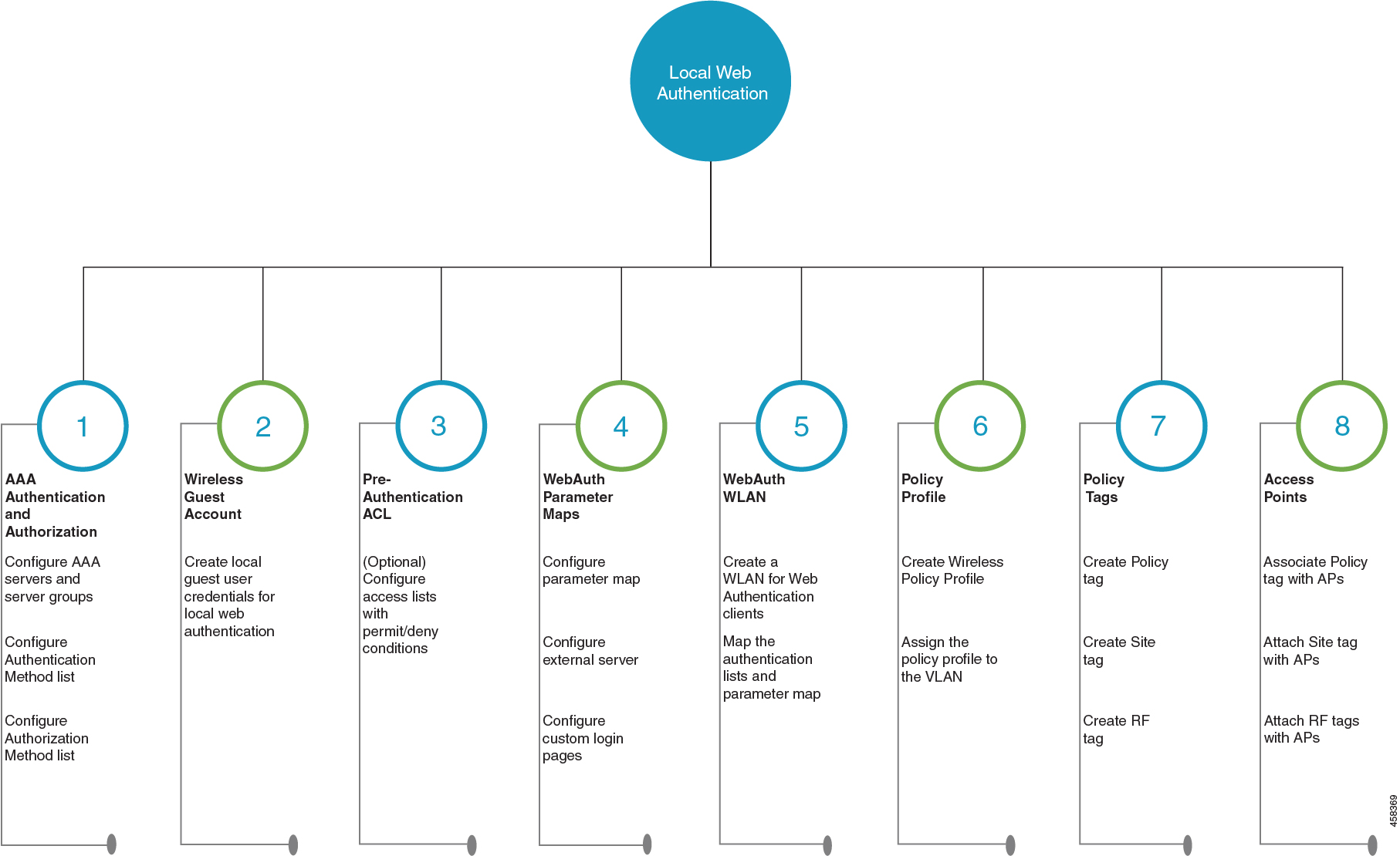
Configure Local Web Authentication using the CLI

Configure AAA Server and Server Groups

When trying to access the WLC, you will be prompted to enter a username and password in order to let you connect to the guest network. By default, these credentials are validated against the local database of users on the controller. Alternatively, you can set up a remote AAA RADIUS or LDAP server for authentication.

Procedure


Step 1

enable

Example:


Device> enable

Enables privileged EXEC mode.

  • Enter your password if prompted.

Step 2

configure terminal

Example:


Device# configure terminal

Enters global configuration mode.

Step 3

To configure LDAP server, do the following:

  1. ldap server server-name

    Example:

     
    Device(config)#ldap server WEBAUTHSERVER
    Defines a LDAP server and enters LDAP server configuration mode.
  2. ipv4 ipv4-address

    Example:

    Device(config-ldap-server)# ipv4 192.168.1.192
    Specifies the LDAP server IP address using IPv4.
  3. bind authenticate root-dn password [0 string | 7 string] string

    Example:

    Device(config-ldap-server)#bind authenticate root-dn admin password 6 Cisco12345

    Use 0 line option to configure an unencrypted shared secret. Use 7 line option to configure an encrypted shared secret.

    Specifies a shared secret text string used between the controller and LDAP server.
  4. base-dn string

    Example:

    Device(config-ldap-server)#base-dn CN=Users,DC=lab,DC=com
    Specifies the base Distinguished Name (DN) of the search.
Step 4

To configure RADIUS server, do the following:

  1. radius server server-name

    Example:

    
    Device(config)#radius server WEBAUTHSERVER
    
    Configures a RADIUS server.
  2. address ipv4 address auth-port auth_port_number acct-port acct_port_number

    Example:

    
    Device(config-radius-server)address ipv4 10.48.71.92 auth-port 1812 acct-port 1813
    
    Specifies the RADIUS server IP address using IPv4.
  3. key key

    Example:

    
    Device(config-radius-server)#key cisco
    
Step 5

To configure TACACS+ server, do the following:

  1. tacacs server server-name

    Example:

    
    Device(config)#tacacs server WEBAUTHSERVER
    
  2. address ipv4 address

    Example:

    
    Device(config-server-tacacs)address ipv4 9.2.62.56
    

    The list-name is a character string used to name the list you are creating. The list-name should not exceed 255 characters.

    Specifies the TACACS+ server IP address using IPv4.
  3. key key

    Example:

    
    Device(config-server-tacacs)#key cisco
    
Step 6

exit

Example:


Device(config-ldap-server)#exit
OR
Device(config-radius-server)#exit
OR
Device(config-server-tacacs+)#exit
Returns to the configuration mode.
Step 7

aaa group server {ldap | radius | tacacs+} server-group

Example:


Device(config-ldap-sg)#aaa group server ldap LDAPGROUP
OR
Device(config-sg-radius)#aaa group server radius RADGROUP
OR
Device(config-sg-tacacs+)#aaa group server tacacs+ TACGROUP

server-group refers to the server group name with a maximum length of 32 strings.

Creates a server-group identification.
Step 8

server name server-name

Example:


Device(config-ldap-sg)#server name WEBAUTHSERVER
OR
Device(config-sg-radius)#server name WEBAUTHSERVER
OR
Device(config-sg-tacacs+)#server name WEBAUTHSERVER
Maps the LDAP/RADIUS/TACACS+ server to the server group.

If you have multiple LDAP/RADIUS/TACACS+ servers that can be used for authentication, it is recommended to map all these servers to the same server group. The WLC handles load balancing different authentications among the servers in the server group.

Step 9

end

Example:


Device(config-ldap-sg)#end
OR
Device(config-sg-radius)#end
OR
Device(config-sg-tacacs+)#end

Exits the global configuration mode and returns to privileged EXEC mode.


Configure Local Authentication and Authorization

A method list is a sequential list describing the authentication and authorization methods to be queried to authenticate a user. Method lists enable you to designate one or more security protocols to be used for authentication and authorization, thus ensuring a backup system in case the initial method fails.

Configure the following steps to specify the local username database as the method of user authentication at login.

Procedure


Step 1

enable

Example:


Device> enable

Enables privileged EXEC mode.

  • Enter your password, if prompted.

Step 2

configure terminal

Example:


Device# configure terminal

Enters global configuration mode.

Step 3

aaa new-model

Example:


Device(config)# aaa new-model

Enables AAA functionality.

Step 4

aaa authentication login {default | list-name} local group AAA-server-group

Example:


Device(config)#aaa authentication login WIRELESS_LWA_AUTHENTICATION local

The list-name is a character string used to name the list you are creating. The list-name should not exceed 255 characters.

group AAA_server_group lets you specify the AAA server group that you have created for authorization.

Sets the login authentication to use the local username database. The default keyword applies the local user database authentication to all ports.
Step 5

aaa authorization network {default | list-name} local group AAA_server_group

Example:


Device(config)#aaa authorization network WIRELESS_LWA_AUTHORIZATION local

group AAA_server_group lets you specify the AAA server group that you have created for authorization.

Creates an authorization method list for external web-based authorization.
Step 6

user-name user name

Example:


Device(config)#username guest

Creates guest user name in the local database, and establishes a username-based authentication system.

For user-name , specify the user ID as one word. Spaces and quotation marks are not allowed.

Step 7

password {encryption-type | password}

Example:


Device(config-user-name)#password cisco123

  • For encryption-type , enter 0 for configuring unencrypted password,6 to configure an encrypted password, 7 to configure a hidden password or 0-9 for nnnot speifying any encryption type.

  • For password , specify the password the user must enter to gain access to the switch. The password must be from 1 to 25 characters, can contain embedded spaces, and must be the last option specified in the username command.

Configures the password for the guest user name in the local database.

Step 8

end

Example:


Device(config-user-name)# end

Exits the global configuration mode and returns to privileged EXEC mode.


Configure Parameter Maps

A parameter map allows you to modify parameters that control the behavior of actions configured under a control policy. A parameter map for web-based authentication sets parameters that can be applied to subscriber sessions during authentication. If you do not create a parameter map, the policy uses default parameters.

Before you begin

  • You have already downloaded and installed a third-party certificate signed by a trusted certificate authority on the controller. Applicable only if you are opting to use third-party certificates.

Procedure


Step 1

enable

Example:


Device>enable

Enables privileged EXEC mode.

  • Enter your password if prompted.

Step 2

configure terminal

Example:


Device#configure terminal

Enters global configuration mode.
Step 3

Configure the global parameter map as follows:

  1. parameter-map type webauth global

    Example:

    
    Device(config)#parameter-map type webauth global


    The parameter-map-name must not exceed 99 characters.

    Creates the global parameter map.
  2. (Optional) virtual-ip {ipv4 | ipv6} virtual-ip-address virtual-host virtual-host-name

    Example:

    
    Device(config-params-parameter-map)#virtual-ip ipv4 192.0.2.1 virtual-host wlc.dnasapaces.com
    
    
    Note 
    You must configure an IPv6 vritual ip address in a dual-stack configuration that includes both IPv4 and IPv6 traffic.

    It is optional to configure a virtual ip address while configuring local web authentication. However if you are using custom web pages, you must configure a virtual ip address using the global parameter map.

    The Virtual IP address for the WLC must be configured as a non-routable IP address. You must ensure it does not overlap with the network infrastructure. The address can be configured to use an IP address from the internal allocated networks. Defined on RFC1918.

    Configures a virtual IP address for redirecting the clients to the login page of the controller.
  3. webauth-http-enable

    Example:

    
    Device(config-params-parameter-map)#webauth-http-enable
    
    
    Enables HTTP server for web authentication.
  4. intercept-https-enable

    Example:

    
    Device(config-params-parameter-map)# intercept-https-enable
    
    
    Note 

    This command is applicable only if you have configured virtual-ip and(or) ip http secure-server commands.

    Enables the clients to redirect to the webauthentication login page when trying to manually access an HTTPS website.
  5. trustpoint trustpoint-name

    Example:

    Device(config-params-parameter-map)# trustpoint trustpoint-name 
    Configures the trustpoint for HTTPS login page. The trustpoint corresponds to the device certificate the WLC will use in conjunction with the virtual IP and hostname.
  6. (Optional) sleeping-client timeout timeout-in-minutes

    Example:

    Device(config-params-parameter-map)# sleeping-client timeout  

    The valid timeout range is between 10 minutes and 43200 minutes. If you do not use the timeout keyword, the sleeping client is configured with the default timeout value of 720 minutes.

    Enable the clients with guest access to sleep and wake up without having to go through another authentication process through the login page. You can configure the duration for which sleeping clients should be remembered for, before reauthentication becomes necessary.
Step 4

Configure the named parameter map as follows:

  1. parameter-map type webauth {parameter-map-name | global }

    Example:

    
    Device(config)# parameter-map type webauth LWA_PARAMETER_MAP
    
    
    Creates a parameter map and enters parameter-map webauth configuration mode.
  2. banner {file file-name | text banner-text title banner-title-text }

    Example:

    
    Device(config-params-parameter-map)# banner file flash:webauth_banner.html
    
    
    • {file file-name allows you to add a logo or a text file to the banner.

    • text banner-text lets you add a custom message to the banner body. You can modify the banner body by directly adding the text using c as the delimiter at the beginning and end of the text string. The text string can containt upto 200 characters.

    • title banner-title-text lets you add a custom banner title to the banner. You can modify the banner title by directly adding the title using c as the delimiter at the beginning and end of the title string. The title string can contain upto 127 characters.

    Note 

    If you use the command without the keywords and arguments, the text Controller's host-name Authentication replaces the default banner body.

    Configures a customized banner on the web authentication login web page.
  3. consent email

    Requests the user’s email address on the web authentication login web page.

  4. (Optional) custom-page {failure | login expired |success } devicelocation:html-filename

    Example:

    
    Device(config-params-parameter-map)#custom-page login device flash:webauth_login.html
    
    Device(config-params-parameter-map)#custom-page login expired device flash:webauth_expire.html
    
    Device(config-params-parameter-map)#custom-page success device flash:webauth_success.html
    
    Device(config-params-parameter-map)#custom-page failure device flash:webauth_fail.html
    

    You must configure all four custom HTML files. If fewer than four files are configured, the internal default HTML pages will be used.

    Note 

    You must configure a virtual IP address if there are external JS or CSS or images references within the custom page. If the virtual ip is not configured, the HTTP requests to fetch the external refs will not be processed by the controller.

    Displays the custom authentication web pages added to the webauth bundle that you have downloaded from cisco.com.
  5. (Optional) max-http-connections number

    Example:

    
    Device(config-params-parameter-map)#max-http-connections 5
    
    
    Specifies the maximum number of HTTP connections for each web authentication client.
  6. (Optional) redirect {{for-login | on-failure | on-success} url | portal {ipv4 ipv4-address | ipv6 ipv6-address}}

    Example:

    
    Device(config-params-parameter-map)# redirect on-failure http://10.10.3.34/~sample/failure.html
    
    Device(config-params-parameter-map)# redirect portal ipv6 FE80::1


    portal {ipv4 ipv4-address | ipv6 ipv6-address}} : Specify the IP address of the web server in the ipv4-address or ipv6-address variables, if you are planning to use an external web server for redirection.

    Redirects the users to a particular URL after authentication.
  7. (Optional) timeout init-state sec seconds

    Example:

    Device(config-params-parameter-map)# timeout init-state sec 60
    Sets the timeout period for a user to complete the authentication.
  8. type {authbypass | consent | webauth | webconsent}

    Example:

    
    Device(config-params-parameter-map)# type webauth
    
    
Note 
Note that authbypass is not supported on wireless web authentication.
Configures the type of web authentication, such as authentication bypass, consent, webauth, or webconsent.

Enables you to configure the global and user-defined parameter maps which is required for external and internal Web Authentication

Configure WLAN Security Parameters

WLAN profile defines the properties of a WLAN such as Profile Name, Status, WLAN ID, L2 and L3 Security parameters, AAA Server associated with this SSID and other parameters that are specific to a particular WLAN.

Before you begin

  • Ensure that you have configured a parameter map for web authentication.

  • Ensure that you have configured a authentication method list for web authentication.

  • Run the show wlan summary command to view the configured security types.

Procedure


Step 1

enable

Example:


Device>enable

Enables privileged EXEC mode.

  • Enter your password, if prompted.

Step 2

configure terminal

Example:


Device#configure terminal

Enters global configuration mode.

Step 3

wlan profile-name wlan-id ssid-name

Example:


Device(config)#wlan wlan_lwa_local 34 WLAN_LWA_LOCAL

Specifies the WLAN name and ID.

profile-name is the WLAN name which can contain 32 alphanumeric characters.

wlan-id is the wireless LAN identifier. The valid range is from 1 to 512.

ssid-name is the SSID which can contain 32 alphanumeric characters.

Step 4

no security wpa

Example:


Device(config-wlan)#no security wpa

Disables the WPA security, if configured.

Step 5

Configure layer 2 security, as required. You can configure open authentication or a combination of any of the following supported security methods.

  • MAB

  • MAB Failure

  • 802.1X

  • PSK

  • iPSK

  • MAB Failure + PSK

  • MAB Failure + OWE

  • MAB Failure + SAE

Step 6

security web-auth

Example:

Device(config-wlan)#security web-auth

Enables web authentication for WLAN.

Step 7

security web-auth {authentication-list authentication-list-name}

Example:

Device(config-wlan)#security web-auth authentication-list WIRELESS_LWA_AUTHENTICATION

Enables authentication list for for web authentication.

authentication-list authentication-list-name : Sets the authentication list for IEEE 802.1X.

Note 
We recommend you to create named authentication list.
Step 8

security web-auth {authorization-list authorization-list-name}

Example:

Device(config-wlan)#security web-auth authorization-list WIRELESS_LWA_AUTHORIZATION

Enables authorization list for for web authentication.

authorization-list authorization-list-name : Sets the override-authorization list for IEEE 802.1X.

Note 
We recommend you to create named authorization list.
Step 9

security web-auth parameter-map parameter-map-name}

Example:

Device(config-wlan)#security web-auth parameter-map LWA_PARAMETER_MAP
Maps the parameter map to the WLAN.
Note 
We recommend you to create a named parameter map.
Step 10

end

Example:

Device(config-wlan)#end

Returns to privileged EXEC mode.


Create Wireless Policy Profile

Policy profile contains policy to be associated with the WLAN. It specifies the settings for client VLAN, Authentication, Authorization, and Accounting (AAA), Access Control Lists (ACLs), session and idle timeout settings and so on.

Before you begin

Ensure you have created the VLANs for assigning the wireless clients.

Procedure


Step 1

enable

Example:


Device> enable

Enables privileged EXEC mode.

  • Enter your password, if prompted.

Step 2

configure terminal

Example:


Device# configure terminal

Enters global configuration mode.

Step 3

wireless profile policy profile-name

Example:

Device(config)#wireless profile wlan_lwa_local

Configures the WLAN policy profile.

Step 4

vlan vlan-name

Example:

Device(config-wireless-policy)#vlan 100

Assigns the profile policy to the VLAN.

Step 5

no shutdown

Example:

Device(config-wireless-policy)# no shutdown

Restarts the WLAN.

Step 6

end

Example:

Device(config)# end

Returns to privileged EXEC mode.


Create a Policy Tag

A policy tag constitutes mapping of the WLAN profile to the policy profile. The WLAN profile defines the wireless characteristics of the WLAN. The policy profile defines the network policies and the switching policies for the client.

You can either create a new policy tag or use the default policy tag. The default policy tag automatically maps any SSID with a WLAN ID between 1 to 16 to the default policy profile. It cannot be modified nor deleted. If you have a WLAN with ID 17 or higher, the default policy tag cannot be used.

Before you begin

  • Ensure you have configured a WLAN for web authentication.

  • Ensure you have configured a WLAN policy profile.

Procedure


Step 1

configure terminal

Example:

Device#configure terminal

Enters global configuration mode.

Step 2

wireless tag policy policy-tag-name

Example:

Device(config)#wireless tag policy lwa_policy_tag

Configures a policy tag and enters policy tag configuration mode.

Step 3

wlan wlan-name policy profile-policy-name

Example:

Device(config-policy-tag)#wlan wlan_lwa_local policy wlan_lwa_local

Maps the WLAN policy profile to a WLAN profile.

Step 4

end

Example:

Device(config-policy-tag)# end

Saves the configuration, exits configuration mode, and returns to privileged EXEC mode.


Configure a Site Tag

Site tag assigns the AP join profile settings to the AP and determines if the site is a local site, in which case the APs will be in local mode.

To get the best performance from your 9800 Series wireless controller, it is recommended that you:

  • Use custom site tags and not the default site tag

  • Assign the same site tag to all the APs in the same roaming domain

  • Limit the number of APs to 500 per site tag for best performance

  • Not exceed the recommended maximum number of APs per site tag based on the controller model

Procedure


Step 1

configure terminal

Example:

Device#configure terminal

Enters global configuration mode.

Step 2

wireless tag site site-tag

Example:

Device(config)#wireless tag site site_lwa

Configures site tag and enters site tag configuration mode. The site is configured as a local site, by default. To configure the site tag as Flexconnect, run the no local-site command.

Step 3

description description

Example:

Device(config-site-tag)# description default site tag

Adds a description for the site tag.

Step 4

end

Example:

Device(config-site-tag)# end

Returns to privileged EXEC mode.


Assign a Policy Tag to an AP

Access Points are tagged based on the broadcast domain, the site it belongs to, and the desired RF characteristics. Once tagged, the AP gets a list of WLANs to be broadcast along with the properties of the respective SSIDs, properties of the APs on the local/remote site, and the RF properties of the network.

Each access point is assigned three unique tags: a policy, site, and RF tag. By default, when an AP joins the Cisco Catalyst 9800 Wireless Controller, it gets default tags; the default policy tag, default site tag, and default RF tag. Users can make changes to the default tags or create custom tags. For more information about tags, see "Tags, Profiles, and SSIDs" chapter in the Cisco Catalyst 9800 Series Wireless Controller Software Configuration Guide.

Before you begin

  • Ensure you have created a policy tag that maps the WLAN profile to the policy profile.

  • Ensure you have created a site tag.

Procedure


Step 1

configure terminal

Example:

Device#configure terminal

Enters the global configuration mode.

Step 2

ap mac-address

Example:

Device (config)#ap 28ac.9eb7.7220

Configures an AP and enters the ap tag configuration mode.

Note 

Use the Ethernet MAC address.

Step 3

policy-tag policy-tag-name

Example:

Device (config-ap-tag)#policy-tag lwa_policy_tag

Maps a policy tag to an AP.

Step 4

site-tag site-tag-name

Example:

Device (config-ap-tag)#site-tag site_lwa

Maps a site tag to an AP.

Step 5

end

Example:

Device (config-ap-tag)#end

Exits the configuration mode and returns to privileged EXEC mode.


Enable the HTTP/HTTPS Server for Web Authentication

Before you begin

Ensure that you have reviewed the Guidelines for Configuring Secure HTTP Access.

Procedure


Step 1

configure terminal

Example:

Device#configure terminal

Enters global configuration mode.

Step 2

ip http server

Example:


Device(config)#ip http server

Enables the HTTP server. The local web authentication feature uses the HTTP server to communicate with the hosts for user authentication.

Note 

It is mandatory to enable ip http server for web authentication.

Step 3

ip http secure-server

Example:


Device(config)#ip http secure-server

Enables secure authentication. With secure authentication enabled, the login page always uses HTTPS even if the client sends an HTTP request.

You can configure custom authentication proxy web pages or specify a redirection URL for successful login.

Note 

To ensure secure authentication when you enter the ip http secure-server command, the login page is always in HTTPS (secure HTTP) even if the user sends an HTTP request.

Step 4

end

Example:

Device(config)# end

Exits configuration mode.


Configure Local Web Authentication using the WebUI

Configure AAA Server and Server Groups

If you are planning to use an AAA server for authenticating the guest users, configure external servers and server groups as follows.

Procedure


Step 1

Choose Configuration > Security > AAA and click Servers/Groups.

Step 2

To create a new RADIUS server, go to the Servers tab, click RADIUS and click + Add.

The Create AAA RADIUS Server window, configure the following details.

  1. In the Name field, enter the name of the RADIUS server.

  2. In the Server Address field, enter the IPv4 or IPv6 address, or hostname.

  3. To enable the Protected Access Credential (PAC) authentication key, check the PAC Key check box.

  4. From the Key Type drop-down list, choose the authentication key type.

    The key types are Clear Text, Encrypted, and Hidden.

  5. In the Key and Confirm Key fields, enter the authentication key.

  6. In the Auth Port field, enter the authorization port number.

  7. the Acct Port field, enter the accounting port number.

  8. In the Server Timeout field, enter the timeout duration, in seconds.

  9. In the Retry Count field, enter the number of retries.

  10. Use the Support for CoA toggle button to enable or disable change of authorization (CoA).

  11. Click Apply to Device.

Step 3

To create a new TACACS+ server, go to the Servers tab, click TACACS+ and click + Add.

  1. In the Name field, enter the name of the TACACS+ server.

  2. In the Server Address field, enter the IPv4 or IPv6 address, or hostname.

  3. In the Key and Confirm Key fields, enter the authentication key.

  4. In the Port field, enter the port number.

  5. In the Server Timeout field, enter the timeout duration, in seconds.

  6. Click Apply to Device.

Step 4

To create a new LDAP server, go to the Servers tab, click LDAP and click + Add.

  1. In the Server Name field, enter the LDAP server name.

  2. In the Server Address field, enter the IPv4 or IPv6 address, or hostname.

  3. In the Port Number field, enter the port number to use.

  4. From the Simple Bind drop-down list, choose the authentication key type.

  5. In the User Base DN field, enter the details.

  6. From the User Attribute drop-down list, choose the user attribute.

  7. In the User Object Type field, enter the object type details and click the + icon.

    The objects that have been added are listed in the area below. Use the x mark adjacent to each object to remove it.

  8. In the Server Timeout field, enter the timeout duration, in seconds.

  9. Check the Secure Mode check box to enable secure mode.

    Checking this enables the Trustpoint Name drop-down list.

  10. From the Trustpoint Name drop-down list, choose the trustpoint.

  11. Click Apply to Device.

Step 5

Choose Configuration > Security > AAA > Server Groups.

You can configure servers of different types in one group. The list of servers in a server group is an ordered list. The first available server in the list is used for authentication.

Step 6

To create a new RADIUS server, go to the Server Groups tab, click RADIUS and click + Add.

The Create AAA RADIUS Server Group window displays.

  1. In the Name field, enter the name of the RADIUS server group.

  2. From the MAC-Delimiter drop-down list, choose the delimiter to be used in the MAC addresses that are sent to the RADIUS servers.

  3. From the MAC Filtering drop-down list, choose a value based on which to filter MAC addresses.

  4. To configure the dead time for the server group and direct AAA traffic to alternative groups of servers that have different operational characteristics, in the Dead-Time field, enter the amount of time, in minutes, after which a server is assumed to be dead.

  5. Choose the servers that you want to include in the server group from the Available Servers list and move them to the Assigned Servers list.

  6. Click Apply to Device.

Step 7

To create a new TACACS+ server, go to the Server Groups tab, click TACACS+ and click + Add.

The Create AAA TACACS Server Group window displays.

  1. In the Name field, enter the name of the TACACS+ server group.

  2. Choose the servers that you want to include in the server group from the Available Servers list and move them to the Assigned Servers list.

  3. Click Apply to Device.

Step 8

To create a new LDAP server, go to the Server Groups tab, click LDAP and click + Add.

The Create AAA LDAP Server Group window displays.

  1. In the Name field, enter the name of the LDAP server group.

  2. Choose the servers that you want to include in the server group from the Available Servers list and move them to the Assigned Servers list.

  3. Click Apply to Device.


Configure Local Authentication and Authorization

Procedure


Step 1

Configure authentication method list as follows. Authentication is the process by which a system or network verifies the identity of a user who wishes to access it.

  1. Choose Configuration > Security > AAA.

  2. Go to AAA Method List tab, click Authentication on the left side and then click + Add.

  3. In the Quick Setup: AAA Authentication window that is displayed, enter a name for your method list in the Method List Name field.

    The name can contain alphanumeric characters including underscores and hyphens. Do not include space.

  4. From the Type drop-down list, choose login to enable web authentication.

  5. From the Group Type drop-down list, choose local to enable local authentication.

    The options are group and local. You have to choose group to enable authentication on an AAA server. To enable authentication locally on the controller, choose local.

  6. If you want to configure a local server as a fallback method when the servers in the groups are unavailable, check the Fallback to local checkbox.

    The Fallback to local checkbox is enabled only if you select the group type as group.

  7. From the Available Server Groups box, select the server groups that you have created in Step 1.

  8. Click Apply to Device.

Step 2

To provide access to system or network resources based on their identity, configure authorization method list as follows:

  1. Choose Configuration > Security > AAA.

  2. Go to AAA Method List tab, click Authorization on the left side and then click + Add.

  3. In the Quick Setup: AAA Authorization window that is displayed, enter a name for your method list in the Method List Name field.

    The name can contain alphanumeric characters including underscores and hyphens. Do not include space.

  4. From the Type drop-down list, choose login to enable web authentication.

  5. From the Group Type drop-down list, choose login to enable local authentication.

    The options are group and local. You have to choose group to enable authentication on an AAA server. To enable authentication locally on the controller, choose local.

  6. If you want to configure a local server as a fallback method when the servers in the groups are unavailable, check the Fallback to local checkbox.

    The Fallback to local checkbox is enabled only if you select the group type as group.

  7. From the Available Server Groups box, select the server groups that you have created in Step 1.

  8. Click Apply to Device.


Configure Local Guest User Credentials

This is applicable only if you are configuring local web authentication. For external web authentication, create the user credentials on the external AAA server.

Before you begin

Procedure


Step 1

Choose Administration > User Administration.

Step 2

To create a new guest user account, click + Add.

Step 3

In the Create User Administration window that is displayed, configure the following mandatory fields, as required.

  1. User Name: Enter a unique user name.

    It can contain alphanumeric characters including underscores and hyphens. Space is not allowed.

  2. Choose the privilege level for the guest user from the Privilege drop-down list.

    The options are Admin, Read Only, No Access and Lobby Admin.

    Click Go to Advanced Mode to view the privilege level number assgined to a particular user.

  3. Type the password in the Password and Confirm Password fields.

    The password must contain a mininum of 6 characters and a maximum of 127 characters.

Step 4

Click Apply to Device.


Configure Parameter Maps

Before you begin

Depending on your configuration options, ensure you have taken care of the following before starting this procedure.

  • The virtual gateway IP address of the WLC that it uses for its communication with the wireless clients is available.

  • You have already installed a third-party certificate signed by a trusted certificate authority on the controller. Applicable only if you are opting to use third-party certificates.

  • The external AAA server is configured for web authentication and the URL is available.

  • The custom HTML pages for authentication are uploaded to the controller or external server, as applicable.

Procedure


Step 1

Configure the Global parameter map as follows:

  1. On the Web Auth page, in the list of parameter maps displayed, click global.

  2. To set the redirect address for web authentication login page, enter the virtual IP address in the Virtual IPv4 Address. If the client uses an IPv6 address, enter the IPv6 address in the Virtual IPv6 Address field.

    It is recommended that you configure a nonroutable IP address for the virtual interface, ideally not overlapping with the network infrastructure addresses.

  3. To specify the hostname for the Virtual IP address used for web authentication, enter the hostname in the Virtual IPv4 Hostname field.

    Configures hostname for the virtual IP address for web authetication.

    Note 
    For web authentication, ensure you configure a hostname that is different from the hostname configured for the management IP address of the WLC, if configured already.
  4. To use third party certificates for secure communication, in the Trustpoint drop-down list, choose the trustpoint label that you have generated for web authentication.

    Maps the third party certificate that you have imported in to the controller to the parameter map. A trustpoint contains the device identity certificate along with the corresponding CA certificate. For information about configuring a trustpoint for web authentication, see "Trustpoint Configuration on 9800" section in Configuring Trustpoints on Cisco Catalyst 9800 Series Wireless Controllers.

  5. To enable secure authentication for the login page, check Web Auth intercept HTTPs checkbox.

    Intercepts HTTPS requests and passes credentials over an encrypted link.

  6. To configure settings for failed login attempts, check Watch List Enable checkbox and enter the watch list timeout period in the Watch List Expiry Timeout field.

    If watch list is enabled, the host is added to the watch list if a user fails to authenticate after the maximum number of login attempts. After the host's IP address is on the watch list, the controller does not intercept HTTP packets from that host or perform WebAuth processing until the expiry timer has expired.

  7. Click Update & Apply.

Step 2

Create a named parameter map as follows:

  1. Choose Configuration > Security > Web Auth.

  2. On the Web Auth page, click Add.

  3. In the Create Web Auth Parameter window that is displayed, enter a name for the parameter map in the Parameter-map name field.

  4. In the Maximum HTTP connections field, enter the maximum number of HTTP connections that you want to allow. The range of value is 1-200.

  5. In the Init-State Timeout field, enter the time after which the init state timer should expire due to the user’s failure to enter valid credentials on the login page. The range is 60-3932100.

  6. In the Type drop-down list, choose the type of Web Authentication page that is displayed during the login process.

    The following are the options available:

    • Webauth: The controller presents a policy page with the user name and password. You need to enter the correct credentials to access the network.

    • Consent: The controller redirects you to a usage policy page with Accept button. You need to click accept the policy to access the network.

    • Webconsent: The controller redirects you to a usage policy page with Accept or Deny buttons along with user name or password. You need to enter the correct credentials and accept the usage policy to access the network.

    • Authbypass: This is not supported.

  7. Click Apply to Device.

    The newly created named parameter map appears in the list of parameter maps in the Web Auth page.

Step 3

Edit a named parameter map as follows:

  1. On the Web Auth page, click the name of the parameter map that you created in step 2.

  2. In the Edit Web Auth Parameter window that is displayed, choose the required Banner Type.

    The banner types available are:

    • None

    • Banner Text: Click the radio button and enter the required banner text to be displayed in the Banner Text field.

    • File Name: Click the radio button and in the File Name field, specify the path of the file from which the banner text has to be fetched.

  3. To set the maximum number of HTTP connections allowed, enter the number in Maximum HTTP connections field.

  4. To enable authentication of sleeping clients and then specify the sleeping client timeout, check the Sleeping Client Status checkbox and enter the timeout period in the Sleeping Client Timeuot field.

    Allows successfully authenticated host devices to stay logged in for a configured period without re-authentication.

    The valid range is between 10 minutes and 43200 minutes.

  5. Click Update & Apply.

    A pop-up with Configuration Successfully Applied message appears.

Step 4

Configure an external server for authentication as follows:

  1. On the Web Auth page, click the name of the parameter map that you created in step 2.

  2. In the Edit Web Auth Parameter window that is displayed, go to the Advanced tab.

  3. Under Redirect to external server, enter the URL of the external server that will host the authentication pages for the login, succesful login and login failure pages.

    • Redirect for log-in

    • Redirect On-Success

    • Redirect On-Failure

  4. In the Portal IPV4 Address field, enter the IPv4 address of the external server to send redirects.

  5. If the external server uses an IPv6 address, in the Portal IPV6 Address field, enter the IPv6 address of the portal to send redirects.

  6. Click Update & Apply.

    A pop-up with Configuration Successfully Applied message appears.

Step 5

Configure custom authentication pages on the controller as follows:

  1. On the Web Auth page, click the name of the parameter map that you created in step 2.

  2. In the Edit Web Auth Parameter window that is displayed, go to the Advanced tab.

  3. Under Customized page, configure the following custom pages, as required. Ensure you have copied all the customized HTML pages to the to the disk or flash of the controller.

    • Login Failed Page

    • Login Page

    • Logout Page

    • Login Successful Page

  4. Choose the HTML pages that you have copied to the flash drive of the controller for each of the options.

  5. Click Update & Apply.

    A pop-up with Configuration Successfully Applied message appears.


Configure Web Authentication WLAN

This topic describes the steps to create a WLAN and map the authentication list and parameter map that you have created for web authentication.

Before you begin

  • Ensure that you have configured an access control list (ACL) for guest users.

  • Ensure that you have configured a parameter map for web authentication.

  • Ensure that you have configured a authentication method list for web authentication.

Procedure


Step 1

Choose Configuration > Tags and Profiles > WLANs.

Step 2

Click Add to add a new WLAN Profile.

Step 3

Enter a profile name in the Profile Name field.

The profile name can contain up to 32 alphanumeric characters.

Step 4

In the SSID field, enter the SSID name.

The SSID name can contain up to 32 alphanumeric characters. By default, the profile name that you have entered in the above step is automatically taken as the SSID. You can go with the default name or add a new one.

Step 5

In the WLAN ID field, enter a valid ID between 1 and 4096.

This field is automatically filled in by the system with an available id. You can assign a new ID, if required.

Step 6

Click the Status toggle button to enable the WLAN.

Step 7

If the Broadcast SSID is disabled, click the toggle button to enable the SSID for broadcast, so that it is visible to all wireless clients within the range.

Step 8

Go to the Security tab and then under Layer2 tab, in the Layer 2 Security Mode list, choose None.

For web authentication, you must disable all layer 2 security features.

Step 9

Under Layer3, check the Web Policy checkbox.

Step 10

In the Web Auth Parameter drop-down list, choose the parameter map that you have created earlier.

Maps the parameter map to the web authentication WLAN.

Step 11

In the Authentication List drop-down list, choose the authentication list that you have created earlier.

Maps the authentication list to the web authentication WLAN.

Step 12

Click Show Advanced Settings, under Preauthentication ACL, choose the preauthentication ACL that you have created for guest users, if any.

Maps the ACL to the web auth WLAN. The preauthentication ACLs are used to provide guests access to DNS and DHCP only. Access to the network is provided only after successful authentication.

Step 13

Click Apply to Device.

The newly added WLAN appears in the list of WLANs configured in the system.


Create Wireless Policy Profile

Policy profile contains policies to be associated with the WLAN. It defines the network policies and the switching policies for the client.

Before you begin

  • Ensure you have created the VLANs for assigning the wireless clients.

  • Ensure you have created the URL Filters for allowing clients access to the external server.

  • Ensure you have created custom preauthentication ACL to allow or block certain traffic which are not available in the default ACLs.

Procedure


Step 1

Choose Configuration > Tags & Profiles > Policy.

Step 2

On the Policy Profile page, click Add.

Step 3

In the Add Policy Profile window, in General tab, enter a name and description for the policy profile.

Step 4

To enable the policy profile, set Status as Enabled.

Step 5

Go to the Access Policies tab and

  1. In the VLAN section, choose the VLAN that you have created for assigning the wireless guest clients in the VLAN/VLAN Group drop-down list.

  2. In the WLAN ACL section, choose the URL filters from the IPv4 ACL and IPv6 ACL drop-down lists.

  3. In the URL Filters section, choose the URL filters from the Pre Auth and Post Auth drop-down lists.

Step 6

Click Apply to Device.

The newly created policy profile appears in the list of profiles configured in the system.


Configure a Policy Tag

A policy tag maps the WLAN profile to the policy profile. You can either create a new policy tag or use the default policy tag. The default policy tag automatically maps any SSID with a WLAN ID between 1 to 16 to the default policy profile. It cannot be modified nor deleted. If you have a WLAN with ID 17 or higher, the default policy tag cannot be used.

Before you begin

  • Ensure you have configured a WLAN for web authentication.

  • Ensure you have configured a WLAN policy profile.

Procedure


Step 1

Configure a Policy Tag as follows:

Step 2

Choose Configuration > Tags & Profiles > Tags.

Step 3

On the Policy tab, click + Add.

Step 4

On the Add Policy Tag dialog box, enter a name for the policy tag in the Name field.

Step 5

Expand WLAN-POLICY Maps, click + Add.

Step 6

In the WLAN Profile drop-down list, choose the WLAN profile that you have configured for web authentication clients.

Step 7

In the Policy Profile drop-down list, choose the policy profile that you have configured for web authentication WLAN.

Step 8

Click the button with a tick mark to save the settings.

Step 9

Click Apply to Device.


What to do next

Assign the policy tag to an Access Point.

Assign a Policy Tag to an AP

Before you begin

  • Ensure you have created a policy tag that maps the WLAN profile to the policy profile.

Procedure


Step 1

Choose Configuration > Wireless > Access Points.

The All Access Points section displays details of all the APs on your network.

Step 2

To edit the configuration details of an AP, click the row for that AP.

The Edit AP window is displayed.

Step 3

In the General tab and Tags section, in the Policy drop-down list, choose the policy tag that you created.

Step 4

If you have configured a site tag and an RF tag, in the Site and RF drop-down lists, choose the tags that you have created.

Step 5

Click Update & Apply to Device.

Step 6

To apply the tags to multiple APs, in the Advanced tab, select the access points by checking the checkboxes for the APs and click + Tag APs.

Step 7

In the Tag APs dialog box, choose the policy tag, site tag and RF tag that you want to assign to the access points and click Apply to Device.