Summary of Cisco Catalyst CW9800H1 and CW9800H2 Wireless Controllers
The Cisco Catalyst CW9800H1 and CW9800H2 Wireless Controllers support:
|
Feature |
Description |
|---|---|
|
Chassis Height |
One rack-unit (1RU) |
|
Processor |
Intel Ice Lake D, 20-cores, 2 GHz |
|
Memory Options |
|
|
Throughput |
80 Gbps |
|
Number of APs supported |
6000 |
|
Number of clients supported |
64000 |
|
TCAM |
80 Mb |
|
Ethernet Port Adapter (EPA) |
3 built-in EPA
|
|
Redundancy Ports |
One 1 GE RJ-45 or 1 (1 GB or 10 GB) SFP port. |
|
Console Port |
One RJ-45 or one micro-USB console port |
|
Service Ports |
1 service port (one RJ-45) |
|
Data Ports |
|
|
USB |
Two USB 3.0 ports |
|
Operating Temperature |
41° to 104° F (5° to 40° C) |
|
Short-term operating temperature |
41° to 122° F (5° to 50° C) |
|
Nominal Operating Humidity |
5 to 85% non-condensing |
|
Short-term Operating Humidity |
5% to 90% non-condensing |
|
Storage temperature |
–4° to 158° F (–20° to +70° C) |
|
Operational Altitude |
0 to 10,000 feet (0 to 3000 meters). |
|
Field-replaceable units (FRU). |
See Chapter 2: Supported Hardware Components for information on supported FRUs. |
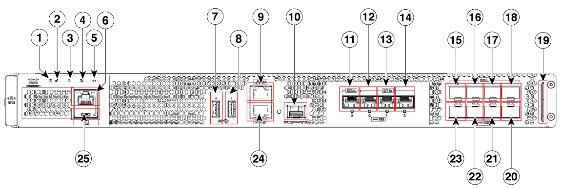
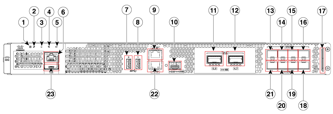
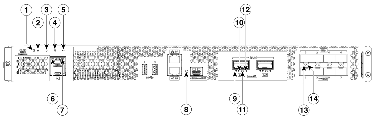
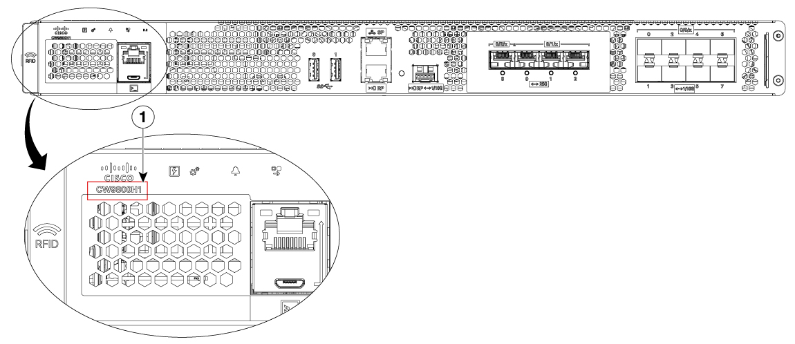
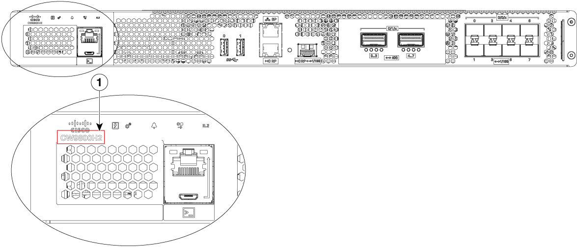
Front View
The following figures show the front view of the Cisco Catalyst CW9800H1 Wireless Controller and Cisco Catalyst CW9800H2 Wireless Controller.
|
1 |
PWR—Power LED |
|
2 |
SYS—System LED |
|
3 |
ALM—Alarm LED |
|
4 |
HA—High-Availability LED |
|
5 |
M.2 SSD |
|
6 |
RJ-45 compatible console port |
|
7 |
USB Port 0 |
|
8 |
USB Port 1 |
|
9 |
SP— RJ-45 1 GE management port |
|
10 |
RP— 1/10-GE SFP port |
|
11 |
TwentyFiveGigE0/2/0 - 25-GE SFP+ EPA2 Port 0 |
|
12 |
TwentyFiveGigE0/1/0 - 25-GE SFP+ EPA1 Port 0 |
|
13 |
TwentyFiveGigE0/1/1 - 25-GE SFP+ EPA1 Port 1 |
|
14 |
TwentyFiveGigE0/1/2 - 25-GE SFP+ EPA1 Port 2 |
|
15 |
Te0/0/0—1-GE SFP/ 10-GE SFP+ Port 0 |
|
16 |
Te0/0/2—1-GE SFP/ 10-GE SFP+ Port 2 |
|
17 |
Te0/0/4—1-GE SFP/ 10-GE SFP+ Port 4 |
|
18 |
Te0/0/6—1-GE SFP/ 10-GE SFP+ Port 6 |
|
19 |
Carrier Label Tray |
|
20 |
Te0/0/7—1-GE SFP/ 10-GE SFP+ Port 7 |
|
21 |
Te0/0/5—1-GE SFP/ 10-GE SFP+ Port 5 |
|
22 |
Te0/0/3—1-GE SFP/ 10-GE SFP+ Port 3 |
|
23 |
Te0/0/1—1-GE SFP/ 10-GE SFP+ Port 1 |
|
24 |
RP— RJ-45 1 GE redundancy port |
|
25 |
CON— 5-pin Micro-B USB console port |
|
1 |
PWR—Power LED |
|
2 |
SYS—System LED |
|
3 |
ALM—Alarm LED |
|
4 |
HA—High-Availability LED |
|
5 |
SSD |
|
6 |
RJ-45 compatible console port |
|
7 |
USB Port 0 |
|
8 |
USB Port 1 |
|
9 |
SP— RJ-45 1 GE management port |
|
10 |
RP— 1/10-GE SFP port |
|
11 |
Fo0/1/0 - 40-GE QSFP Port 0-3 |
|
12 |
Fo0/1/1 - 40-GE QSFP Port 4-7 |
|
13 |
Te0/0/0—1-GE SFP/ 10-GE SFP+ Port 0 |
|
14 |
Te0/0/2—1-GE SFP/ 10-GE SFP+ Port 2 |
|
15 |
Te0/0/4—1-GE SFP/ 10-GE SFP+ Port 4 |
|
16 |
Te0/0/6—1-GE SFP/ 10-GE SFP+ Port 6 |
|
17 |
Carrier Label Tray |
|
18 |
Te0/0/7—1-GE SFP/ 10-GE SFP+ Port 7 |
|
19 |
Te0/0/5—1-GE SFP/ 10-GE SFP+ Port 5 |
|
20 |
Te0/0/3—1-GE SFP/ 10-GE SFP+ Port 3 |
|
21 |
Te0/0/1—1-GE SFP/ 10-GE SFP+ Port 1 |
|
22 |
RP— RJ-45 1 GE redundancy port |
|
23 |
CON— Micro-USB console port |
 Warning |
Never install an AC power module and a DC power module in the same chassis. Statement 1050 |
 Note |
For the Cisco Catalyst CW9800H1 and CW9800H2 Wireless Controllers, the power supplies (PEM 0 and PEM1), are located in the rear side of the chassis. See the Rear View section. |
Built-In SFP and SFP+ Ports
The following figures show the port numbering for the built-in ports.

|
1 |
|
2 |
Bay 0—8 X 1-GE/10-GE SFP ports. The supported ports are:
|

|
1 |
Bay 1—2 X 40-GE QSFP ports. The supported ports are:
|
2 |
Bay 0—8 X 1-GE/10-GE SFP ports. The supported ports are:
|
The port LEDs behave as follows:
-
Off—Indicates the port is not enabled by software.
-
Amber—Indicates the port is enabled by software but there is a problem with the link.
-
Green—Indicates the port is enabled by software and there is valid link.
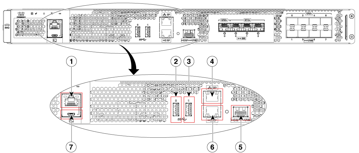
Management and Storage Connections
The following figure shows the management and storage connections for the Cisco Catalyst CW9800H1 Wireless Controller and the Cisco Catalyst CW9800H2 Wireless Controller.
|
1 |
RJ-45 compatible console port |
5 |
RP—1-GE/10-GE SFP port |
|
2 |
USB port 0 |
6 |
RP—RJ-45 1 GE redundancy port |
|
3 |
USB port 1 |
7 |
CON-Micro-USB console port |
|
4 |
SP—RJ-45 1 GE management port |
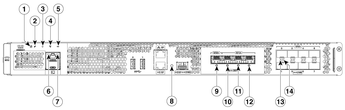
LEDs
The following figure shows the LEDs on the front panel of the Cisco Catalyst CW9800H1 Wireless Controller and Cisco Catalyst CW9800H2 Wireless Controller.
|
No. |
LED Label |
Description |
LED Color |
Behavior |
|---|---|---|---|---|
|
1 |
PWR |
Power |
Green
|
If all the power rails are based on the specification. |
|
2 |
SYS |
System |
On
|
Remains ON during IOS boot complete. |
|
Blinking Green
|
Remains blinking when IOS booting is in progress. |
|||
|
Amber
|
Remains ON during system crash. |
|||
|
Blinking Amber
|
Remains blinking during secure boot failure. |
|||
|
Off |
Remains OFF during ROMMON boot. |
|||
|
3 |
ALM |
Alarm |
Green
|
Remains ON during ROMMON boot complete. |
|
Blinking Green
|
Remains blinking when system upgrade is in progress. |
|||
|
Amber
|
Remains ON during ROMMON and SYSTEM bootups. |
|||
|
Blinking Amber
|
Remains blinking during temperature error and secure boot failure. |
|||
|
Red |
Indicates that the system detects critical warnings. |
|||
|
Off |
Remains OFF during IOS boot. Normal Operation |
|||
|
4 |
HA |
High Availability |
Green
|
Remains ON when HA is active. |
|
Blinking Green
|
Remains blinking when HA Standby Hot. |
|||
|
Amber
|
Blinks slowly when booted or HA Standby Cold. |
|||
|
Blinks Fast |
Blinks fast during HA maintenance. |
|||
|
5 |
M.2 SSD |
SSD Activity |
Green
|
Indicates active usage of the hard disk SSD memory devices in the unit. |
|
6 |
RJ-45 Console Port Status LED |
Green
|
Indicates that the RJ-45 console port is active. |
|
|
7 |
USB console Port LED |
Green  |
Indicates that the micro USB connector is used as the console. |
|
|
8 |
RP SFP Port |
Green |
Indicates that the port is enabled and there is a valid Ethernet Link |
|
|
Amber
|
Indicates that the port is enabled, but there is a problem with the Ethernet Link. |
|||
|
OFF |
Indicates that the port is not enabled. |
|||
|
9, 10, 11, 12 |
Built-in EPA 1 and EPA 2 (SFP + status LEDs with 1 per port) |
OFF |
Indicates that the port is not enabled. |
|
|
Amber
|
Indicates that the port is enabled, but there is a problem with the Ethernet Link. |
|||
|
Green |
Indicates that the port is enabled and there is a valid Ethernet Link |
|||
|
13 |
1/10 GE SFP Port Status LED (1 per port for ports 0,2,4, and 6) |
OFF |
Indicates that the port is not enabled. |
|
|
Amber
|
Indicates that the port is enabled, but there is a problem with the Ethernet Link. |
|||
|
Green |
Indicates that the port is enabled and there is a valid Ethernet Link |
|||
|
14 |
1/10 GE SFP Port Status LED (1 per port for ports 1, 3,5, and 7) |
OFF |
Indicates that the port is not enabled. |
|
|
Amber
|
Indicates that the port is enabled, but there is a problem with the Ethernet Link. |
|||
|
Green |
Indicates that the port is enabled and there is a valid Ethernet Link |


|
No. |
LED Label |
Description |
LED Color |
Behavior |
|---|---|---|---|---|
|
1 |
PWR |
Power |
Green
|
If all the power rails are based on the specification. |
|
2 |
SYS |
System |
On
|
Remains ON during IOS boot complete. |
|
Blinking Green
|
Remains blinking when IOS booting is in progress. |
|||
|
Amber
|
Remains ON during system crash. |
|||
|
Blinking Amber
|
Remains blinking during secure boot failure. |
|||
|
Off |
Remains OFF during ROMMON boot. |
|||
|
3 |
ALM |
Alarm |
Green
|
Remains ON during ROMMON boot complete. |
|
Blinking Green
|
Remains blinking when system upgrade is in progress. |
|||
|
Amber
|
Remains ON during ROMMON and SYSTEM bootups. |
|||
|
Blinking Amber
|
Remains blinking during temperature error and secure boot failure. |
|||
|
Red |
Indicates that the system detects critical warnings. |
|||
|
Off |
Remains OFF during IOS boot. Normal Operation |
|||
|
4 |
HA |
High Availability |
Green
|
Remains ON when HA is active. |
|
Blinking Green
|
Remains blinking when HA Standby Hot. |
|||
|
Amber
|
Blinks slowly when booted or HA Standby Cold. |
|||
|
Blinks Fast |
Blinks fast during HA maintenance. |
|||
|
5 |
M.2 SSD |
SSD Activity |
Green
|
Indicates active usage of the hard disk SSD memory devices in the unit. |
|
6 |
RJ-45 Console Port Status LED |
Green
|
Indicates that the RJ-45 console port is active. |
|
|
7 |
USB console Port LED |
Green |
Indicates that the micro USB connector is used as the console. |
|
|
8 |
RP SFP Port |
Green |
Indicates that the port is enabled and there is a valid Ethernet Link |
|
|
Amber
|
Indicates that the port is enabled, but there is a problem with the Ethernet Link. |
|||
|
OFF |
Indicates that the port is not enabled. |
|||
|
9,10, 11, and 12 |
Built-in EPA 1 (QSFP + status LEDs with 1 per port) |
OFF |
Indicates that the port is not enabled. |
|
|
Amber
|
Indicates that the port is enabled, but there is a problem with the Ethernet Link. |
|||
|
Green |
Indicates that the port is enabled and there is a valid Ethernet Link |
|||
|
13 |
1/10 GE SFP Port Status LED (1 per port for ports 0,2,4, and 6) |
OFF |
Indicates that the port is not enabled. |
|
|
Amber
|
Indicates that the port is enabled, but there is a problem with the Ethernet Link. |
|||
|
Green |
Indicates that the port is enabled and there is a valid Ethernet Link |
|||
|
14 |
1/10 GE SFP Port Status LED (1 per port for ports 1, 3,5, and 7) |
OFF |
Indicates that the port is not enabled. |
|
|
Amber
|
Indicates that the port is enabled, but there is a problem with the Ethernet Link. |
|||
|
Green |
Indicates that the port is enabled and there is a valid Ethernet Link |
Rear View
The following figure shows the rear view of the Cisco Catalyst CW9800H1 and Cisco Catalyst CW9800H2 Wireless Controllers.

|
1 |
Grounding lug |
2 |
Fans |
|
3 |
Power supply (PEM 1) |
4 |
Power supply (PEM 0) |
|
5 |
Power/standby switch |
The chassis has a front-to-rear airflow. Six internal fans draw cooling air in through the front of the chassis and across internal components to maintain an acceptable operating temperature. The fans are located at the rear of the chassis. The fans are numbered from 0 to 5, right to left.
 Caution |
The power supplies used in the controllers are different and they should not be mixed or swapped. The size and structural dimensions are the same, therefore they both look alike. It would be hazardous, if you accidentally inserted the wrong power supply into the PEM slot. |
 Feedback