Mounting the Controller
This section describes the various mounting options for the controller:
Mounting the Controller on Desktop or Shelf
Before mounting the controller on a desktop or shelf, install the rubber feet located in accessory kit shipped with the controller.
To install the rubber feet to the controller, follow these steps:
Procedure
|
Step 1 |
Locate the rubber feet on the black adhesive strip that is shipped with the controller. 
|
||||
|
Step 2 |
Place the controller upside down, on a smooth, flat surface. |
||||
|
Step 3 |
Peel off the rubber feet from the black adhesive strip and press them adhesive-side down onto the bottom four corners of the controller, see the figure below: 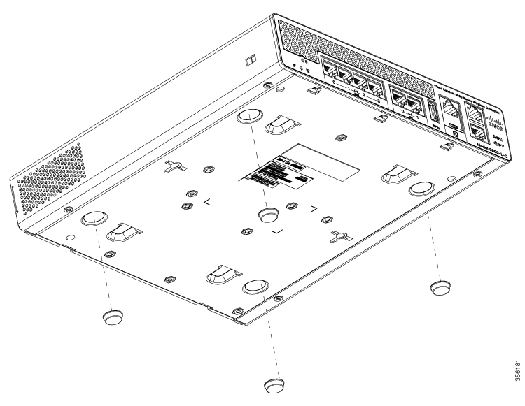 |
||||
|
Step 4 |
Place the controller right-side up on a flat, smooth, secure surface. |
||||
|
Step 5 |
Connect the interface cables. |
Mounting the Controller on a Wall
 Note |
Do not wall-mount the device with its front panel facing up. Following safety regulations, wall-mount the device with its front panel facing down or to the side to prevent airflow restriction and to provide easier access to the cables. |
 Warning |
Read the wall-mounting carefully before beginning installation. Failure to use the correct hardware or to follow the correct procedures could result in a hazardous situation to people and damage to the system. Statement 378. |
Note |
Wall mounting screws are not supplied. Installer must supply proper screws in accordance with local codes. Controller wall mount holes located on the bottom of the enclosure fit standard #6 or M3 Pan Head screw. The type of screw used to mount to wall should follow local guidelines for wall type and material. |
To mount the controller on a wall using mounting screws, follow these steps:
Procedure
|
Step 1 |
Mark the location of the mounting screws on the wall. Use the mount hole locations on the back of the controller for placement of the mounting screws. Mounting screw spacing is 6 1/8 inch (155.4 mm). |
||
|
Step 2 |
Install two screws and tighten until the top of the screws are 1/8 inch (3 mm) from the wall (leaving enough room for the back panel to slide onto the screws firmly). |
||
|
Step 3 |
Place the controller onto the mounting screws and slide it down until it lock into place, as shown in figure below:
 |
||
|
Step 4 |
After the controller is mounted on the wall, perform the following tasks to complete the installation
|
||
|
Step 5 |
For configuration instructions about using the CLI setup program, see the (Link to Running the Bootup script section). |
Rack Mounting the Controller
Warning |
To prevent bodily injury when mounting or servicing this unit in a rack, you must take special precautions to ensure that the system remains stable. The following guidelines are provided to ensure your safety:
Statement 1006 |
Warning |
Take care when connecting units to the supply circuit so that wiring is not overloaded. Statement 1018. |
To mount the controller in a 19-inch equipment rack, you can order an optional Optional Rack Mount kit (C9800-RMNT= Cisco Catalyst 9800-L Wireless Controller Rack Mount Tray).
The rack-mount tray is designed for 19 racks and uses two rack-units spaces. To rack-mount the controller, perform the following steps:
Procedure
|
Step 1 |
Remove the four rubber feet if previously installed. |
||
|
Step 2 |
Slide the Cisco Catalyst 9800-L Wireless Controller in position such that the 4-tray tabs align and latch into the bottom of the unit as it is pushed in place. The front of the Cisco Catalyst 9800-L Wireless Controller should be flush against the front edge of the tray. A nylon latch in the center of the tray snaps into and locks the Cisco Catalyst 9800-L Wireless Controller in place.   |
||
|
Step 3 |
Remove power supply baffle in rear tray. Baffles secure with tabs circled.  |
||
|
Step 4 |
Place the power adapters between either of the two tabs in the rear of the tray and use the provided velcro straps to secure them. |
||
|
Step 5 |
Route the AC wiring through the cable management clips. |
||
|
Step 6 |
Re-install and secure tabs on power supply baffle, coil extra cables, and locate them under the baffle.
|
||
|
Step 7 |
Attach the rack mount tray to the rack using the supplied screws and brackets, as shown in figures below: 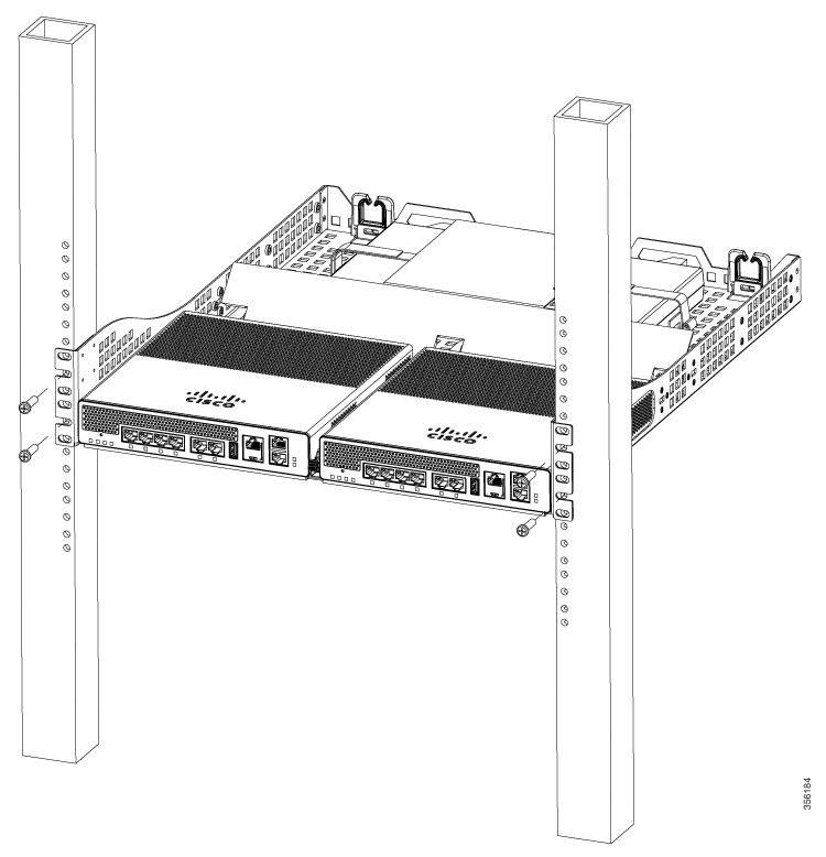 
 To remove the chassis from the rack, remove the screws that attach the chassis to the rack, and then remove the chassis. |
||
|
Step 8 |
(optional): If required install the rear rack mount bracket for additional stability on four-post racks. Include optional orderable rear rack mount adapter kit: C4948E-BKT-KIT= C49xxE front and rear mount brackets. |

 Feedback