Cisco Workgroup Bridges
A workgroup bridge (WGB) is a Cisco access point that can be configured in a mode that permits it to associate with a wireless infrastructure, providing network access on behalf of wired clients. The WGB mode is supported on autonomous IOS (Wave 1) APs and on some Wave 2 APs.
A Cisco WGB provides information about its wired clients via Internet Access Point Protocol (IAPP) messaging. This enables the wireless infrastructure to know the MAC addresses of the WGB’s wired clients. Up to 20 wired clients are supported behind a Cisco WGB.
In 8.10 release, the following APs support WGB operational mode: 2800, 3800, 4800, 1560 and 6300.

 Note |
If the lightweight access point fails, the WGB attempts to associate to another access point. |
-
The following features are supported for use with a WGB:
-
Guest N+1 redundancy
-
Local EAP
-
Open, WPA+TKIP, WPA2+AES, LEAP, EAP-FAST, PEAP, and EAP-TLS authentication modes
-
-
Wired clients connected to the WGB are not authenticated for security. Instead, the WGB is authenticated against the access point to which it associates. Therefore, we recommend that you physically secure the wired side of the WGB.
-
Wired clients connected to a WGB inherit the WGB’s QoS and AAA override attributes.
-
To enable the WGB to communicate with the lightweight access point, create a WLAN and make sure that Aironet IE is enabled.
-
If you have to apply ACL to WGB during run time, do not modify the ACL configuration for interface in the controller during run time. If you need to modify any ACLs, then you must disable all WLANs that are in the controller or disable both the 802.11a and 80.11b networks. Also, ensure that there are no clients associated and mapped to that interface and then you can modify the ACL settings.
This section contains the following subsections:
Guidelines and Restrictions for Cisco Workgroup Bridges
-
The WGB can associate only with Cisco lightweight access points.
-
The following features are not supported for use with a WGB:
-
Idle timeout
-
Web authentication
-
-
Aironet WGBs are not supported if the parent AP is configured for FlexConnect local switching with local authentication, if the parent AP is a Wave 2 AP (that is, 802.11ac Wave 2 or 802.11ax). For more information, see CSCvh22645.
-
With Layer 3 roaming, if you plug a wired client into the WGB network after the WGB has roamed to another controller (for example, to a foreign controller), the wired client’s IP address displays only on the anchor controller, not on the foreign controller.
-
If a wired client does not send traffic for an extended period of time, the WGB removes the client from its bridge table, even if traffic is continuously being sent to the wired client. As a result, the traffic flow to the wired client fails. To avoid the traffic loss, prevent the wired client from being removed from the bridge table by configuring the aging-out timer on the WGB to a large value using the following Cisco IOS commands on the WGB:
configure terminal
bridge bridge-group-number aging-time seconds
exit
end
where bridge-group-number is a value between 1 and 255, and seconds is a value between 10 and 1,000,000 seconds. We recommend configuring the seconds parameter to a value greater than the wired client’s idle period.
-
When you deauthenticate a WGB record from a controller, all of the WGB wired clients’ entries are also deleted.
-
These features are not supported for wired clients connected to a WGB:
-
MAC filtering
-
Link tests
-
Idle timeout
-
-
The broadcast forwarding toward wired WGB clients works only on the native VLAN. If additional VLANs are configured, only the native VLAN forwards broadcast traffic.
-
Associating a WGB to a WLAN that is configured for Adaptive 802.11r is not supported.
Workgroup Bridge (WGB) Downstream Broadcast On Multiple VLANs
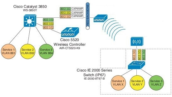
Cisco Wireless LAN Controller (WLC) Release 8.3 provides an enhancement to broadcast traffic support on multiple 802.1Q VLAN workgroup bridge (WGB) deployments that traverse mesh networks and in Local mode. Specifically, support for WGB downstream broadcasts over multiple VLANs (to differentiate and prioritize traffic); and, bridging of VLAN traffic to wired clients connected to the WGB. Applications for this functionality are commonly found in the transportation and mining industries. For more information, see CSCub87583.
Supported platforms:
-
Access point (AP) and WGB support:
-
IW3700 Series
-
Supported AP mode:
-
Local mode
-
Bridge mode
Prerequisites
You need to create the dynamic interfaces and bind them to the interface group before you proceed with the configuration.
-
Create the dynamic interfaces, by choosing on WLC. Add any dynamic interface that needs to support the downstream broadcast on Multiple VLANs feature into the interface group.
-
Bind the dynamic interfaces with Interface Groups, by choosing on WLC.
-
Bind the Interface Groups to WLAN. Choose WLAN. Under the specific WLAN General confirmation tab, choose the proper interface group.
Cisco Wireless Controller Configuration (CLI Only)
To enable or disable the downlink broadcast packet VLAN tagging on a WLAN (new command):
(Cisco Controller) >config wlan wgb broadcast-tagging {enable | disable} wlan-id
Note |
This feature is disabled by default. |
Note |
To enable this feature, you need to enable Broadcast Forwarding on WLC, by choosing and choose Enabled from the Broadcast Forwarding drop-down list. |
Note |
To enable this feature, you should also configure the AP Multicast Mode to Multicast rather than Unicast, by clicking and choosing Multicast, and then assign Multicast Group Address. |
WGB Configuration (CLI Only)
You can configure the following on Workgroup Bridges:
-
Broadcast Tagging
-
Native VLANs
By default, Broadcast Tagging is disabled.
By default, only Native VLAN broadcasts can be forwarded to wired clients in Native VLANs.
You use the no command to disable VLAN configurations on the WGB as shown in the examples below.
Note |
When you have multiple VLAN configurations on WGB, you need to configure the encryption cipher mode and keys as the following example shows: Then, you should configure the encryption cipher mode globally on the multicast or broadcast interface by entering the following command: |
VLAN Broadcast Tagging Configuration
-
To enable broadcast tagging on a VLAN (new command):
(WGB) (config)#workgroup-bridge unified-vlan-client broadcast-tagging
-
To disable broadcast tagging on a VLAN:
(WGB) (config)#no workgroup-bridge unified-vlan-client broadcast-tagging
Note |
The no workgroup-bridge unified-vlan-client broadcast-tagging command will disable workgroup-bridge unified-vlan-client as well. Make sure you have workgroup-bridge unified-vlan-client configured properly to enable the multiple vlan feature. |
Reliable WGB Downstream Broadcast for Multiple VLANs
Cisco Wireless Controller (WLC) Release 8.10.130.0 provides an enhancement for the Workgroup Bridge (WGB) Downstream Broadcast On Multiple VLANs feature, which was first introduced in Release 8.3. Legacy broadcast without 802.11 ACK mechanism’s may have more chance to cause packet loss over the air. With reliable downstream broadcast feature, broadcast packet can be converted to unicast packet. Hence the Root AP will receive the ACK for converted broadcast packet and retransmit in case of missing ACK.
The converted unicast packet's header will be changed from 3-address to 4-address format. WGB’s MAC address will be used as receiver address (RA) instead of broadcast address and special multicast address with VLAN information will be used as destination address (DA). This BC2UC conversion for multiple VLAN’s is possible for WGB and its wired clients. Since the converted packet is a unicast packet, Root AP will receive the ACK for each packet and retransmit based on the retry logic by the Root AP for every ACK which is not received for this broadcast to unicast conversion.
Note |
This enhancement is for WGB and its wired clients. It will not impact the non-WGB wireless clients. |
-
Supported AP platforms:
-
Cisco Industrial Wireless 3700 Series Access Points
-
Cisco Aironet 1570 Series Access Points
-
-
Supported WGB platforms:
-
Cisco Industrial Wireless 3700 Series Access Points
-
-
Supported AP modes:
-
Local
-
Bridge
-
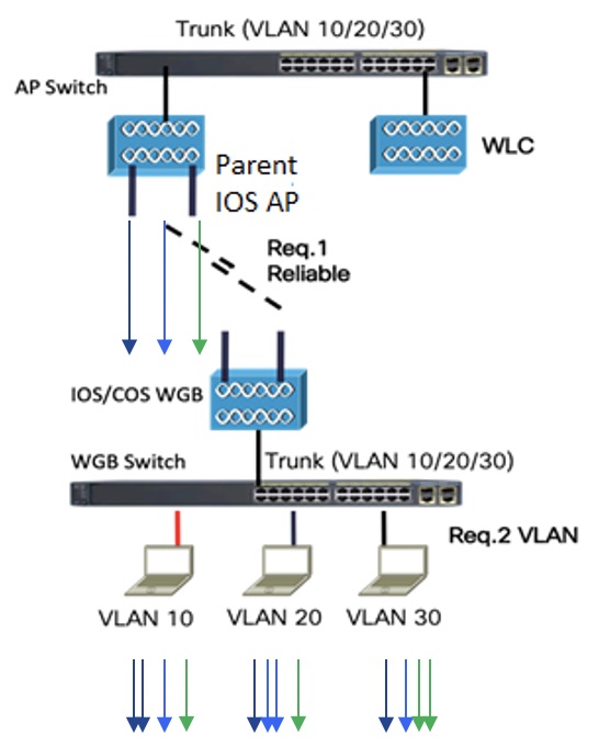
As shown in the following figure, a WGB with wired clients of three different VLANs (VLAN 10, 20, and 30) joins the IOS AP wireless network. The broadcast traffic from AP to WGB will be transmitted to the clients with corresponding VLAN and retransmission will happen if traffic is lost on air.
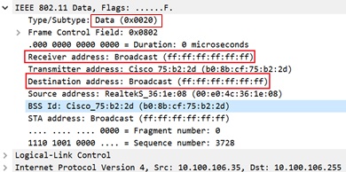
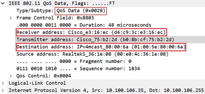
The Receiver address (RA) of legacy broadcast packet is FF:FF:FF:FF:FF:FF and there will not be any retransmission if the packet is lost in the air. The reliable downstream broadcast feature replaces this RA with WGB address and Destination address (DA) with special multicast address 01:00:5e:80:xx:xx. This will make the packet as a unicast packet and enables ACK mechanism. The packet will be retransmitted when the ACK is not received.
The multicast address 01:00:5e:80:xx:xx is introduced to transmit the VLAN information between AP and WGB. The VLAN value is embedded in 2 LSB of this multicast address. Both IOS and COS WGB support to decode this type of packet.
Root AP will make "N" copies for single broadcast packet for "N" WGBs associated to it on the specific VLAN. Also, non-converted packet will be sent for the benefit of non-WGB clients. Broadcast packets will not get converted if there is no WGBs associated on the specific VLAN.
QOS behavior:
-
The new packet is a 802.11e Qos data.
-
The 802.11e QoS priority of reliable broadcast packets will follow multicast default priority value from WLAN’s QOS configuration.
The configuration similarities and changes between Release 8.10.130.0 and Release 8.3 are as following:
-
Similarities:
-
Dynamic interface for all VLANs must be created on the WLC. It is necessary for multi-vlan support in both Release 8.10.130.0 and Release 8.3.
-
Broadcast-tagging configurations are same on WLC and WGB for both Release 8.10.130.0 and Release 8.3.
-
-
Changes:
-
Interface-group must be configured in Release 8.3 to support downstream multiple VLANs. But in 8.10.130.0, it can be supported with or without interface-group configuration on the WLAN.
-
Broadcast packets are converted to multicast packets by Root AP in Release 8.3. While in Release 8.10.130.0, broadcast packets will be converted to unicast packets by Root AP.
-
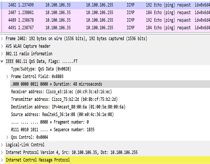
The following figures illustrate an example of 802.11 packet forwarding from VLAN 106 (0x006a). The receiver address changes from FF:FF:FF:FF:FF:FF to the MAC address of WGB Radio (d4:c9:3c:e3:16:ec), and the destination address changes from FF:FF:FF:FF:FF:FF to 01:00:5E:80:00:6a (the last two bytes in MAC address represents corresponding VLAN in hexadecimal).
Cisco Wireless Controller (WLC) Configuration
This section provides the basic configuration for AireOS controller.
-
To enable or disable reliable broadcast traffic for IOS AP, configure broadcast-tagging on the WLAN from AireOS WLC:
(Cisco Controller)> config wlan wgb broadcast-tagging <enable|disable> <wlan-id> -
To support reliable broadcast feature, basic broadcasting forwarding and global multicast feature should be enabled on WLC first. The following commands are for basic broadcast forwarding and global multicast configuration.
-
To enable global broadcast forwarding:
(Cisco Controller)> config network broadcast enable -
To configure AP multicast mode:
(Cisco Controller)> config network multicast mode multicast multicast_Group_Address
-
WGB Configuration
To support multiple VLAN on IOS WGB, the following CLI should be configured on WGB:
WGB(config)#workgroup-bridge unified-vlan-client To enable broadcast tagging on a VLAN:
WGB(config)#workgroup-bridge unified-vlan-client broadcast-tagging To disable broadcast tagging on a VLAN:
WGB(config)#no workgroup-bridge unified-vlan-client broadcast-tagging WGB will received both FF:FF:FF:FF:FF:FF and 01:00:5e:80:xx:xx packet on the native VLAN. By default, WGB will forward the normal broadcast (FF:FF:FF:FF:FF:FF) and discard the reliable broadcast (01:00:5e:80:xx:xx). If the CLI is enabled, WGB will forward the reliable broadcast (01:00:5e:80:xx:xx) to corresponding VLAN’s wired client and discard the normal broadcast (FF:FF:FF:FF:FF:FF).
Troubleshooting Reliable Broadcast
This section describes the troubleshooting of reliable broadcast on WLC, Root AP, and WGB.
-
Troubleshooting on WLC:
-
Use the show wlan <wlanid> command to check if broadcast tagging is enabled.
(WLC) > show wlan 3 Universal Ap Admin............................... Disabled Broadcast Tagging................................ Enabled -
Use debug capwap payload enable to check the mgid information sent to AP.
*spamApTask0: Feb 19 18:14:51.384: b0:8b:cf:75:b2:20 L2_MCAST_MGID_INFO : payload 0 addOrDelete 1, mgidByte[0] 0, mgidByte[1] 10 *spamApTask0: Feb 19 18:14:51.384: b0:8b:cf:75:b2:20 MCAST_MGID_INFO_PAYLOAD vapId 3, isL3Mgid FALSE, numOfMgid 1, vlanInterfaceId 10 -
Use the debug pem events command to check the association of WGB and its wired clients.
*iappSocketTask: Feb 19 14:05:38.379: 00:e0:4c:53:44:58 sending to spamAddMobile (wgb wired client) vlanId 106 mgid 11 numOfMgid 1
-
-
Troubleshooting on Root AP:
-
Use the show capwap mcast mgid all command to display L2 MGID information.
IOS-AP#show capwap mcast mgid all L2 MGID Information: L2 MGID = 0 WLAN bit map (all slots) = 0x0001 VLAN ID = 103 Slot map/tx-cnt: R0:0x0001/3446 R1:0x0001/3446 R2:0x0001/0 L2 MGID = 1 WLAN bit map (all slots) = 0x0001 VLAN ID = 0 Slot map/tx-cnt: R0:0x0001/7828 R1:0x0001/7828 R2:0x0000/0 L2 MGID = 11 WLAN bit map (all slots) = 0x0001 VLAN ID = 106 Slot map/tx-cnt: R0:0x0001/14 R1:0x0001/14 R2:0x0001/0 -
Use the show capwap mcast mgid id <mgid value> command to display the details of a specific MGID.
IOS-AP#show capwap mcast mgid id 11 L2 MGID = 11 WLAN bit map (all slots) = 0x0001 VLAN ID = 106 Slot map/tx-cnt: R0:0x0001/979 R1:0x0001/979 R2:0x0001/0 rx pkts = 979 tx packets: wlan : 0 1 2 3 4 5 6 7 8 9 10 11 12 13 14 15 slots0 : 0 0 0 0 0 0 0 0 0 0 0 0 0 0 0 0 slots1 : 979 0 0 0 0 0 0 0 0 0 0 0 0 0 0 0 slots2 : 0 0 0 0 0 0 0 0 0 0 0 0 0 0 0 0 Reliable BCAST Clients: 1 Client: d4c9.3ce3.16ec --- SlotId: 1 WlanId: 0 ConvertedBCASTtx: 263 -
Use the debug capwap mcast command to get the information of WGB and its wired clients added to the BC2UC client list.
*Dec 19 21:09:29.795: CAPWAP MCAST: capwapAddEntryToL2MgidList:Added new client d4c9.3ce3.16ec to mgid 11 list of vlan 105, Total clients in this list: 1. *Dec 19 21:10:56.491: CAPWAP MCAST: capwapAddEntryToL2MgidList:Added new client d4c9.3ce3.16ec to mgid 10 list of vlan 106 for wired client f076.1cdc.b22c, Total clients in this list: 1. -
Use debug dot11 dot11radio <0|1> trace print xmt to check the transmission of original and converted broadcast packet.
Converted Packet(4-address format):
*May  6 14:04:40.859: 613B6145 t a8.1b2s0  - 8803 000 48B89C 75B22C m01005E 16F0 361E08 q4 l92
   IP 10.100.106.255 < 10.100.106.56 f1-0-0 id 0 ttl64 sum 50AA prot 1 len 84
  ICMP ping code 0 chk F4D7, id 20765 seq 330
  CF77 B25E 0000 0000 6F17 0100 0000 0000 1011 1213 1415 1617 1819 1A1B 1C1D

Original packet (3-address format):
*May  6 14:04:40.859: 613B6204 t 18     0  - 0802 000 mFFFFFF 75B22C 361E08 C020 l92
   IP 10.100.106.255 < 10.100.106.56 f1-0-0 id 0 ttl64 sum 50AA prot 1 len 84
  ICMP ping code 0 chk F4D7, id 20765 seq 330
-
-
Troubleshooting on WGB:
-
Use the show running-config command to check the status of workgroup unified-vlan-client and workgroup-bridge unified-vlan-client broadcast-tagging.
-
Use the debug dot11 forwarding command to check whether the IOS WGB has recovered the VLAN information from converted broadcast packet.
*Sep 15 02:54:24.775: Unified WGB convert specific mcast+vlan pak to ffff.ffff.ffff:0080.483f.d5f6 on Virtual-Dot11Radio0 received, link 7, dest_vlan_id 0x402F <- 2F (Vlan id) -
Use the debug dot11 events command to check whether the IOS WGB has received the original broadcast packet and dropped.
*Feb 4 17:41:19.081: Unified WGB drop original none-tagged bcast pak from source 00e0.4c36.1e08, ethertype: 0x0800, linktype: 7 -
Use the debug dot11 dot11radio <0|1> trace print rcv command to check converted packets and original packets.
Converted Packet:
*Nov 27 15:27:23.727: CB8823A0 r  m6-2   24/128/128/128 71- 8803 02C 48B89C AD9A70 m01005E 06A0 392AC9 q4 l92
 4500 0054 0000 4000 4001 56C9 0A64 6719 0A64 67FF 0800 2E6A 1556 03BF
 B74B DE5D 0000 0000 5604 0600 0000 0000 1011 1213 1415 1617 1819 1A1B 1C1D
 1E1F 2021 2223 2425 2627 2829 2A2B 2C2D 2E2F 3031 3233 3435 3637 4860 6C3D

Original Packet:
*Nov 27 15:27:23.727: CB88246F r 18      21/128/128/128 74- 0802 000 mFFFFFF AD9A70 392AC9 4610 l92
 4500 0054 0000 4000 4001 56C9 0A64 6719 0A64 67FF 0800 2E6A 1556 03BF
 B74B DE5D 0000 0000 5604 0600 0000 0000 1011 1213 1415 1617 1819 1A1B 1C1D
 1E1F 2021 2223 2425 2627 2829 2A2B 2C2D 2E2F 3031 3233 3435 3637 0000 0000
-
Use Sniffer to capture packet over the air or on the wired side when the detailed packet information is needed.
The following figure shows the original packet details.
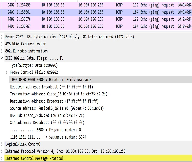
The following figure shows the converted packet details.
Parallel Redundancy Protocol Enhancement on AP and WGB
Cisco Wireless Release 8.4 provides the Parallel Redundancy Protocol (PRP) enhancement to improve wireless network availability for wired clients behind Workgroup Bridge (WGB), and improve the roaming performance by allowing wired clients to have dual wireless connections.
PRP allows a data communication network to prevent data transmission failures by providing two alternate paths for the traffic to reach its destination. Two Ethernet networks (LANs) with similar topology are completely separated.
A device that requires protection for data across the network connects to the two independent networks (LAN-A and LAN-B) is called a Dual Attached Node implementing PRP (DANP). A DANP source sends two frames simultaneously on both LANs. A DANP destination receives both frames and discards the duplicating. If one LAN fails, a DANP destination can still receive a frame from the other LAN.
Non-redundant endpoints in the network that attach only to either LAN-A or LAN-B are known as Singly Attached Nodes (SANs). A Redundancy Box (RedBox) is used when a single interface node must be attached to both networks. Such a node can communicate with all other nodes. The switch implements RedBox functionality is a PRP switch.
To implement the PRP function for this release, you need to connect the AP and WGB to a PRP switch. The PRP switch is to offload PRP processing. AP or WGB is to keep dual wireless connections. You can have two WGBs interconnected through an external PRP switch and wirelessly connected to a single fixed AP or two fixed APs. Two WGBs can roaming between APs. Redundant packet transmissions can be supported over either single or both 2.4 GHz and 5 GHz. The infrastructure side also needs a PRP switch for AP side.
For the application where both WGBs may roam at the same time, the roaming coordination feature is introduced to avoid roaming gaps and guarantee staggered roaming. In this release, only dual radio links roaming coordination across two WGBs is supported for roaming coordination.
Supported platforms and AP mode:
-
WLC and AP on the infrastructure side—FlexConnect AP mode (central authentication, local switching), the following IOS based platforms are supported: IW3702, 2700, 3700, and 1570 series.
-
WGB on the client side—Only supported for IW3700 Series
-
Roaming coordination—Only supported for IW3700 Series
Sample Network Configuration
General guidelines for this configuration:
-
Separation of expected redundancy in the network:
-
Traffic expecting redundancy mapped to two reserved SSID A and SSID B each with specified VLAN.
-
Each WGB is configured to connect either SSID A or SSID B.
-
Others traffic without expectation of redundancy is recommended to be mapped to other SSID.
-
-
WGB supports unified VLAN function and it is recommended that wired clients not to use VLANs assigned to SSID A or SSID B.
-
Wired clients connected to WGB are source and recipients of redundancy traffic.
The following figure shows a topology of concurrent wireless transmission via two WGBs paired with one PRP switch, commonly used in train transportation.
On the train side, the PRP switch (in this example, Cisco IE2000U) duplicates upstream packets and sends both packets simultaneously via two different ports, Gi0/1 and Gi0/2. The dual packets will pass from different WGBs or APs, to ensure that at least one packet reaches the destination. On the track side, one more PRP switch is added to each aggregating endpoint along the track. The PRP switch on the track side will remove the duplicating for upstream packets. The same redundancy for downstream packet is also available by the pair of PRP switches.
Note |
The throughput of this solution depends on the network elements depicted in the diagram. Each element along the wired and wireless transmission path should validate its throughput to avoid being the throughput bottleneck. |

WLC Configuration (CLI Only)
To enable or disable PRP on a WLAN (new command):
(Cisco Controller)> config wlan wgb prp {enable|disable} <wlan id>
enable              Enable Parallel Redundancy Protocol (PRP) feature on a WLAN
disable             Disable Parallel Redundancy Protocol (PRP) feature on a WLAN
Note |
This feature is disabled by default. |
This CLI will enable two WLANs to allow dual associations in flex-connect mode. It will also enable the AP to forward packets to or from WGB wired clients with double tags in flex-connect mode.
Note |
To enable unified VLANs in the WGB, the existing command config wgb vlan enable should also be executed. You should configure the inner VLAN (VLAN for wired client) on WLC as well. |
WGB Configuration for Roaming Coordination (CLI Only)
For Parallel Redundancy Protocol (PRP), wired client traffic will be duplicated to transmit in dual radio links in two WGBs. Dual radio links without any radio link coordination have the possibility to trigger roaming at the same time, so that the traffic will be broken in a short window time.
The following figure is a typical PRP scenario of train transportation. AP like IW3702 has two physical Ethernet ports. Gig0 will be exclusively used to bridge PRP traffic. Gig1 will be used for internal communication. Gig 1 will connect to a non-PRP port on the PRP switch or connect to a peer Gig1 port directly.

Configuration of Dual Radio Coordination on Two WGBs
Follow these steps to configure dual radio coordination on two WGBs:
-
Configure service VLAN.
Use the following command to enable the service VLAN traffic that will be punted to local handling process for sub interface on Gig0 or Gig1.
WGB(config)# workgroup-bridge service-vlan <vlan id> -
Configure peer coordinator address.
Use the following commands to set peer coordinator address and create the coordination communication process. For example, if you have configured the service VLAN to 50, you should configure the local/peer coordinator address under sub interface 50.
WGB(config)# interface GigabitEthernet1.50 WGB(config-subif)# encapsulation dot1q 50 WGB(config-subif)# ip coordinator peer-addr <addr> -
Configure dot11 radio coordinator on two WGBs.
Use the following commands to create dot11 coordinator process, and enable dot11 roaming coordinator service on radio 0 or radio 1.
WGB(config)# dot11 coordinator uplink single [radio 0|radio 1] -
Configure dot11 coordination roaming waiting timer.
Use the following command to set the dot11 coordination roaming waiting timer. The default is 100ms.
WGB(config)# dot11 coordinator timeout roam-wait [value] -
Configure Dot11 roaming coordination bypass.
Use the following command to bypass roaming coordination decision on WGB. When configured, it is used to collect WGB’s roaming conflict statistics, and will not affect the current roaming behavior.
WGB(config)# dot11 coordinator bypass -
Configure to avoid bridge loop.
Wired network on WGB side can introduce a bridge loop if you connect the Gig1 port of WGBs directly or via a switch. The following sample configurations can avoid the bridge loop.
Note
The coordination traffic is forwarded on service VLAN and will not be blocked.
-
To avoid bridge loop when connecting the Gig1 port of WGBs directly, configure the following on both WGBs:
WGB(config)# access-list 700 deny 0000.0000.0000 ffff.ffff.ffff WGB(config)# interface gigabitEthernet 1 WGB(config-if)# l2-filter bridge-group-acl WGB(config-if)# bridge-group 1 WGB(config-if)# bridge-group 1 output-address-list 700 -
To avoid traffic loop when connecting two WGBs via a switch, configure the following on the switch port:
interface GigabitEthernet0/3
switchport trunk allowed vlan 50
switchport mode trunk

interface GigabitEthernet0/4
switchport trunk allowed vlan 50
switchport mode trunk
-
WLC Configuration
Note |
For more information about WLC configuration for FlexConnect, see the FlexConnect Chapter in the Cisco Wireless Controller Configuration Guide. |
Follow these steps to configure the wireless controller for FlexConnect:
-
Create two WLANs with the SSID PRP1 and PRP2.
-
Enable local switching for each WLAN.
Note |
For any wired client within the service vlan, you need to create a corresponding dynamic interface with the same service vlan on WLC. |
Configuration of AP
-
Configure AP to FlexConnect mode and join WLC.
-
Enable VLAN support on each AP, and make sure PRP SSID is included.
Configuration of WGBs
-
WGB1 Configuration
hostname WGB1 dot11 ssid PRP1 vlan 801 authentication open interface Dot11Radio1 no ip address ssid PRP1 antenna gain 0 stbc beamform ofdm station-role workgroup-bridge ! interface Dot11Radio1.800 encapsulation dot1Q 800 bridge-group 2 bridge-group 2 spanning-disabled ! interface Dot11Radio1.801 encapsulation dot1Q 801 native bridge-group 1 bridge-group 1 spanning-disabled ! interface GigabitEthernet0 no ip address duplex auto speed auto ! interface GigabitEthernet0.800 encapsulation dot1Q 800 bridge-group 2 ! interface GigabitEthernet0.801 encapsulation dot1Q 801 native bridge-group 1 ! interface BVI1 mac-address 4c00.821a.c0b0 ip address dhcp ipv6 address dhcp ipv6 address autoconfig ipv6 enable ! bridge 1 route ip ! workgroup-bridge unified-vlan-client -
WGB2 Configuration
hostname WGB2
dot11 ssid PRP2
   vlan 802
   authentication open
interface Dot11Radio1
 no ip address
 !
 ssid PRP2
 !
 antenna gain 0
 stbc
 beamform ofdm
 station-role workgroup-bridge
!
interface Dot11Radio1.800
 encapsulation dot1Q 800
 bridge-group 2
 bridge-group 2 spanning-disabled
!
interface Dot11Radio1.802
 encapsulation dot1Q 802 native
 bridge-group 1
 bridge-group 1 spanning-disabled
!
interface GigabitEthernet0
 no ip address
 duplex auto
 speed auto
!
interface GigabitEthernet0.800
 encapsulation dot1Q 800
 bridge-group 2
!
interface GigabitEthernet0.802
 encapsulation dot1Q 802 native
 bridge-group 1
!
interface BVI1
 mac-address f872.eae4.a4d8
 ip address dhcp
 ipv6 address dhcp
 ipv6 address autoconfig
 ipv6 enable
bridge 1 route ip
workgroup-bridge unified-vlan-client
Aggregated Switch Configuration
Agg-SW# show run int fa 1/0/1
description ***AP1***
 switchport trunk encapsulation dot1q
 switchport trunk native vlan 201
 switchport trunk allowed vlan 201,801,802
 switchport mode trunk
end


Agg-SW#show run int fa 1/0/3
Building configuration...


Current configuration : 196 bytes
!
interface FastEthernet1/0/3
 description ***AP2***
 switchport trunk encapsulation dot1q
 switchport trunk native vlan 201
 switchport trunk allowed vlan 201,801,802
 switchport mode trunk
end

Agg-SW# show run int fa 1/0/7
Building configuration...


Current configuration : 178 bytes
!
interface FastEthernet1/0/7
 description ***PRP-Track-SW***
 switchport access vlan 801
 switchport trunk encapsulation dot1q
 switchport mode dot1q-tunnel
 no cdp enable
end


Agg-SW# show run int fa 1/0/8
Building configuration...


Current configuration : 178 bytes
!
interface FastEthernet1/0/8
 description ***PRP-Track-SW***
 switchport access vlan 802
 switchport trunk encapsulation dot1q
 switchport mode dot1q-tunnel
 no cdp enable
PRP Switch Configuration
interface PRP-channel1
 switchport mode trunk
interface GigabitEthernet0/1
 switchport mode trunk
 no ptp enable
 no cdp enable
 prp-channel-group 1
!
interface GigabitEthernet0/2
 switchport mode trunk
 no ptp enable
 no cdp enable
 prp-channel-group 1
Note |
For the PRP configurations on the Cisco IE switches, refer to Parallel Redundancy Protocol Software Configuration Guide for Industrial Ethernet 2000U Series Switches. |
Verifying the PRP Configurations
Follow these steps to verify the PRP configurations:
Before you begin
-
Create an SVI interface on the train side PRP switch with service vlan: 800.
-
Configure the SVI interface on the track side PRP switch with service vlan: 800, and create the DHCP pool.
Procedure
| Step 1 |
On the train side PRP switch, use the following command to check whether an IP address has been assigned to Vlan 800 from the DHCP pool on the track side. Example: |
| Step 2 |
On the track side PRP switch, use the following command to display ingress packet statistics. In this example, LAN A and LAN B both have one packet. Example: |
| Step 3 |
On the train side PRP switch, ping the track side with the following command, to send 5 packets from the train to the track side: Example: |
| Step 4 |
On the track side PRP switch, use the following command to display the number of packets that LAN A and LAN B have received, and the number of duplicated packets that have been discarded. In this example, after receiving 5 packets, both LAN A and LAN B have 6 packets in total. Example: |
Dual Radio Parallel Redundancy Protocol Enhancement on WGB
The Cisco Wireless LAN Controller (WLC) Release 8.5 provides the Dual Radio Parallel Redundancy Protocol (PRP) enhancement as the second phase of the PRP feature. .
This feature enables dual radio (2.4G and 5G) workgroup bridge mode on a WGB simultaneously. The WGB is wirelessly connected to the access points, with redundant packet transmissions over 2.4 GHz and 5 GHz subsystem.
Supported platforms and access point mode:
-
WLC and AP on the infrastructure side—FlexConnect AP mode (central authentication, local switching), the following IOS based platforms are supported: IW3702, 2700, 3700, and 1570 series.
-
WGB on the client side—Only supported for IW3700 Series
-
Roaming coordination—Only supported for IW3700 Series
Sample Network Configuration
Concurrent Wireless Transmission Via One WGB With Dual Radio and Paired With One PRP Switch shows a topology of concurrent wireless transmission via one WGB with dual radio and paired with one PRP switch.
The WGB (Cisco IW3702 Access Point) duplicates upstream packets and sends both packets simultaneously via 2.4 GHz and 5 GHz. The duplicated packets will pass to the access points, to ensure that at least one packet reaches the destination. On the infrastructure side, a PRP switch (for example, Cisco IE4000) is added to each aggregating endpoint. The PRP switch on the infrastructure side will remove the duplicating for upstream packets. The same redundancy for downstream packet is also implemented by the pair of PRP switch and WGB.
Note |
The throughput of this solution depends on the network elements depicted in the diagram. Each element along the wired and wireless transmission path should validate its throughput to avoid being the throughput bottleneck. |

Configuration of Roaming Coordination on a Single WGB
As the client traffic will be duplicated to transmit in dual radio links of one WGB, radio link coordination is necessary to avoid the possibility to trigger roaming at the same time, which will cause the traffic to be broken in a short window time.
-
Configure dot11 dual radio coordinator on one WGB.
WGB(config)# dot11 coordinator uplink both
-
Configure dot11 coordination roaming waiting timer. The value of the timer is from 50–150 ms. The default is 100 ms.
WGB(config)# dot11 coordinator timeout roam-wait [value ]
WLC Configurations
This section contains the configurations on WLC to enable PRP under WLAN and multiple vlan support.
Note |
When you create WLAN, the BSSID of WLAN (mapping to 2.4G radio) and the BSSID of WLAN (mapping to 5G radio) must be different. |
Note |
From release 8.5, you can configure the PRP settings via both CLI and GUI. |
Enabling PRP Under WLAN by CLI
-
Use the following command to enable PRP under WLAN. The value of WLAN ID is between 1 and 512.
(WLC)> config wlan wgb prp enable <WLAN id >
-
Use the following command to check the PRP status:
(WLC)> show wlan <WLAN id >
The output of this show command displays the PRP status as below:
Universal Ap Admin............................... Disabled
Broadcast Tagging................................ Disabled
PRP.............................................. Enabled
Enabling PRP Under WLAN by GUI
To enable PRP under WLAN in GUI, choose WLAN -> Advanced . In the WGB PRP field, select the checkbox in front of Enable .
Enabling Multiple Vlan Support by CLI
Use the following command to enable or disable the multiple vlan support:
(WLC-PRP)> config wgb vlan {enable|disable}
enable Enable WGB Vlan Client Support
disable Disable WGB Vlan Client Support
Enabling Multiple Vlan Support by GUI
To enable multiple vlan support in GUI, choose Controller -> General . In the WGB Vlan Client field, choose Enable from the drop-down list.
WGB Configurations
This section contains the commands on WGB to configure the PRP settings.
Enabling PRP Mode on WGB
The following commands enable the PRP submode on WGB.
iw3702(config)# dot11 wgb prp
iw3702(config-prp)# no shutdown
Note |
PRP is disabled by default after the dot11 wgb prp command is executed. To enable the PRP feature, execute the no shutdown command. |
Submode PRP Configuration Commands
-
bvi-vlanid—Configure vlan id of the BVI interface.
-
dummy-ip—Configure dummy ip for the radio interface.
-
shutdown—Disable the PRP feature.
-
exit—Exit from prp sub-mode.
-
no—Negate a command or set its defaults.
Configuring Dummy IP Address for Radio Interface
Use the following command to configure the dummy ip address for the radio interface to associate to the access point. By default the IP address will be assigned as 1.1.X.Y and 1.1.X.(Y+1) to 2.4G and 5G, where X and Y are the last 2 bytes of the WGB’s Ethernet MAC address.
iw3702(config-prp)# dummy-ip <IP_addr >
Configuring Vlan for BVI Under PRP Mode
Use the following command to configure Vlan for BVI under PRP mode. If not configured, the BVI interface cannot get IP address via DHCP under PRP mode.
iw3702(config-prp)# bvi-vlanid <Vlan_Id >
Note |
The vlan configured by the bvi-vlanid command is reserved for BVI only. Do not use it for any wired clients. |
Configuration Example of WGB
This section provides an example of the WGB configuration. .
hostname Vehicle
!
dot11 wgb prp
  no shutdown
  bvi-vlanid 900
!
dot11 ssid PRP1
   vlan 801
   authentication open
   no ids mfp client
!
dot11 ssid PRP2
   vlan 802
   authentication open
   no ids mfp client
!
interface Dot11Radio0
 no ip address
 load-interval 30
 !
 ssid PRP1
 !
 antenna gain 0
 antenna a-antenna
 packet retries 32 drop-packet
 station-role workgroup-bridge
 rts retries 32
 bridge-group 1
 bridge-group 1 spanning-disabled
!
interface Dot11Radio0.800
 encapsulation dot1Q 800
 bridge-group 50
 bridge-group 50 spanning-disabled
!
interface Dot11Radio0.801
 encapsulation dot1Q 801
 bridge-group 100
 bridge-group 100 spanning-disabled
!
interface Dot11Radio1
 no ip address
 load-interval 30
 !
 ssid PRP2
 !
 antenna gain 0
 antenna a-antenna
 peakdetect
 packet retries 32 drop-packet
 station-role workgroup-bridge
 rts retries 32
 bridge-group 1
 bridge-group 1 spanning-disabled
!
interface Dot11Radio1.800
 encapsulation dot1Q 800
 bridge-group 50
 bridge-group 50 spanning-disabled
!
interface Dot11Radio1.802
 encapsulation dot1Q 802
 bridge-group 200
 bridge-group 200 spanning-disabled
!
interface GigabitEthernet0
 no ip address
 load-interval 30
 duplex auto
 speed auto
 bridge-group 1
 bridge-group 1 spanning-disabled
!
interface GigabitEthernet0.800
 encapsulation dot1Q 800
 bridge-group 50
 bridge-group 50 spanning-disabled
!
interface GigabitEthernet1
 no ip address
 shutdown
 duplex auto
 speed auto
 bridge-group 1
 bridge-group 1 spanning-disabled
!
interface BVI1
 mac-address 0081.c408.c594
 ip address dhcp
 ipv6 address dhcp
 ipv6 address autoconfig
 ipv6 enable
!
bridge 1 route ip
!
workgroup-bridge unified-vlan-client
end
Aggregated Switch Configuration
interface FastEthernet1/0/1
 description ***AP1***
 switchport trunk encapsulation dot1q
 switchport trunk native vlan 201
 switchport trunk allowed vlan 201,801,802
 switchport mode trunk
end

interface FastEthernet1/0/3
 description ***AP2***
 switchport trunk encapsulation dot1q
 switchport trunk native vlan 201
 switchport trunk allowed vlan 201,801,802
 switchport mode trunk
end
interface FastEthernet1/0/4
 description ***PRP-Track-SW***
 switchport access vlan 801
 switchport trunk encapsulation dot1q
 switchport mode dot1q-tunnel
 no cdp enable
end

interface FastEthernet1/0/5
 description ***PRP-Track-SW***
 switchport access vlan 802
 switchport trunk encapsulation dot1q
 switchport mode dot1q-tunnel
 no cdp enable
PRP Switch Configuration
interface PRP-channel1
 switchport mode trunk
interface GigabitEthernet1/1
 switchport mode trunk
 no ptp enable
 no cdp enable
 prp-channel-group 1
interface GigabitEthernet1/2
 switchport mode trunk
 no ptp enable
 no cdp enable
 prp-channel-group 1
Verifying the Configuration
-
Verify the packet replication and discarding details.
Vehicle# show dot11 wgb prp
available uplink count: 0
Index: 0 Status: DOWN Name: Dot11Radio0 Virtual-Dot11Radio0 AP: cc46.d616.ad84
Index: 1 Status: DOWN Name: Dot11Radio1 Virtual-Dot11Radio1 AP: cc46.d616.ad8a
======== Statistic counters ===========================
cnt_total_sent_A_: 5481     <= RADIO 0 REPLICATION
cnt_total_sent_B_: 940       <= RADIO 1 REPLICATION
cnt_tx_difference: 4541
cnt_total_received_A_: 337   <= RADIO 0 DISCARDING
cnt_total_received_B_: 56     <= RADIO 1 DISCARDING
cnt_rx_difference: 281
cnt_total_errors_A_: 0
cnt_total_errors_B_: 0
cnt_total_discard: 1              <= DISCARDED PACKET COUNT
cnt_discard_table_used_items: 0
max_duplicate_delay_: 0
-
Display the roaming coordination status.
WGB# show coordinator status
current coordinator role is: Master
-
Display the roaming coordination statistics.
WGB# show dot11 coordinator statistics
Vehicle#show dot11 coordinator statistics
Dot11 Roaming Coordination CURRENT Statistics:
                         Total Roaming Count: 1034
--------------------------------------------------------------------------------
      Scheduled Roaming: 1034                   Forced Roaming: 0
--------------------------------------    --------------------------------------
RATESHIFT          RSSI                   MAXRETRY           BEACON_LOST
0                  1034                   0                  0
--------------------------------------
Backoff     Timeout       Immediate
3           1             1030
------------------------
Master Conflict: 4          Slave Conflict: 0
----------------------------------------------------
            Total Conflict Count: 4
Dot11 Roaming Coordination FULL Statistics:
                         Total Roaming Count: 1034
--------------------------------------------------------------------------------
      Scheduled Roaming: 1034                   Forced Roaming: 0
--------------------------------------    --------------------------------------
RATESHIFT          RSSI                   MAXRETRY           BEACON_LOST
0                  1034                   0                  0
--------------------------------------
Backoff     Timeout       Immediate
3           1             1030
------------------------
Conflict: 4
Roaming Coordination Settings
--------------------------------------------------------------------------------
Current Roaming Wait Timeout: 100 ms
Debug Commands
-
Clear roaming coordination statistics.
clear dot11 coordinator {all|current} statistics -
Clear PRP statistics.
clear dot11 wgb prp statistics -
Debug roaming coordination.
-
Use the following command to view the primary-subordinate role and communication related debug information:
debug coordinator {detail|error|event|packet|timers -
Use the following command to view dot11 radio roaming coordination related debug information:
debug dot11 coordinator {detail|error|event|timers
-
-
Disable PRP debug messages on CLI.
no debug dot11 prp {bvi|config|uplink|forward|event|trailer|bypass -
Debug PRP configuration.
debug dot11 prp {bvi|config|uplink|forward|event|trailer|bypass
DLEP Client Support on WGB
Radio Aware Routing (RAR) is a mechanism where radios can interact with routing protocols (such as OSPFv3 or EIGRP, but only EIGRP is supported in this feature) to signal the appearance, disappearance, and link conditions of one-hop routing neighbors. The Dynamic Link Exchange Protocol (DLEP) is a radio aware routing (RAR) protocol, which addresses the challenges faced when merging IP routing and radio frequency (RF) communications.
The DLEP client support feature allows the workgroup bridge (WGB) to report radio link metrics to a router, for example, the Cisco Embedded Services Router (ESR). The WGB acts as the DLEP client, and the ESR acts as the DLEP server. The uplink selection is based on radio link quality metrics. For example, when two WGBs are deployed in a truck, there are redundancy radio links. The link with better radio quality while the truck is moving can be selected before the radio link completely goes down.
There are two methods of DLEP peer discovery, auto discovery and manual configuration. In this release, only the manual configuration method is supported.
Note |
This feature applies to the IW3700 Series. Only DLEP version 7 is supported. |
Configuring the Physical Interface
The DLEP session is established between ESR and WGB through wired Ethernet interface. Static IP address needs to be configured under BVI interface. Subinterface of Gigabit Ethernet is also supported. But the subinterface should be configured with the same VLAN as the wireless interface. Here is an example:
interface GigabitEthernet0.811
encapsulation dot1Q 811
ip address 8.1.1.50 255.255.255.0
ip dlep local-port 38682 server-addr 8.1.1.211 server-port 55556
Configuring DLEP Local TCP Port and Server Address
Use the following command to enable the WGB to work as a DLEP client and configure the DLEP local port and server address.
wgb(config-if)# ip dlep local-port x server-addr x.x.x.x server-port x
Once configured, the WGB will listen on the configured local port for incoming DLEP connections.
Configuring Optional DLEP Timers
Configuring Heartbeat Timer
Use the following command to set the interval for the DLEP client to wait before declaring a DLEP server peer failed.
wgb(config-if)# ip dlep set heartbeat-timer x
The value range of the heartbeat timer is from 1 to 60 seconds. The default value is 5 seconds. The new heartheat timer value will take effect in the next new dlep session.
Configuring Neighbor Update Interval
Use the following command to set the interval for DLEP client to send neighbor update event in millisecond.
wgb(config-if)# ip dlep set neighbor-update-interval x
The value range of the neighbor update interval is from 100 to 5000 milliseconds. If not specified, the default value is 4000 milliseconds. The new neighbor update timer will take effect in the next new DLEP session. The WGB will send neighbor update message which contains radio metrics to the DLEP server every x milliseconds. Neighbor update interval will impact ESR response speed when link state changes. It is recommended to set a shorter neighbor-update-interval for high speed roaming. For example, you may set neighbor-update-interval to 500ms when WGB’s moving speed is up to 80km/h.
Configuring DLEP Neighbors
The WGB uses the radio interface to detect neighbor and neighbor’s metrics. Configure DLEP neighbor information under the radio interface.
Configuring Neighbor MAC Address
Use the following command to configure routing neighbor MAC address:
wgb(config-if)# dlep neighbor <mac address >
(Optional) Configuring RSSI Threshold and CDR Threshold
Use the following command to configure RSSI and CDR threshold:
wgb(config-if)# dlep neighbor <mac address > rssi-threshold x cdr-threshold x
Use the following command to configure RSSI threshold:
wgb(config-if)# dlep neighbor <mac address > rssi-threshold x
The value range of RSSI threshold is 1–100 dbm. The default value is 80 dbm. Once the RSSI value is above the configured RSSI threshold, the WGB will send neighbor update message including all the radio metrics to the DLEP server immediately.
Use the following command to configure CDR threshold:
wgb(config-if)# dlep neighbor <mac address > cdr-threshold x
The value range of CDR threshold is 7-6000 mbps. If not configured, no event will be triggered no matter what the current data rate is. Once configured, the neighbor update will be sent to the DLEP server when the current data rate is lower than the configured CDR threshold.
Note |
For roaming scenarios, the neighbor update will be sent out immediately after the roaming is completed. |
Note |
There are two ways to trigger the metric update. One is the event trigger which is controlled by rssi-threshold or cdr-threshold. The other is the timer trigger which is controlled by the neighbor update interval. |
Verifying DLEP Configuration
Displaying DLEP Configuration
The following command shows information about DLEP configurations, such as the server’s IP address, port, heartbeat threshold, and peer-terminate-ack-timeout value.
WGB# show dlep config
 local tcp port=38682
 local ipv4=8.1.1.50
 router tcp port=55556
 router ipv4=8.1.1.211
 Type Description: no type description
 local ID=0
 peer offer tiemout=5 seconds
 peer heartbeat interval=5 seconds
 peer heartbeat missed threshold=3
 peer termination ack timeout=1000 milliseconds
 peer termination missed ack threshold=3
 neighbor up ack timeout=1000 milliseconds
 neighbor up missed ack threshold=3
 neighbor update interval timeout=4000 milliseconds
 neighbor activity timer=10 seconds
 neighbor down ack timeout=1000 milliseconds
 neighbor down missed ack threshold=3
Displaying DLEP Peer Information
The following command provides DLEP peer (DLEP server for WGB) information.
WGB# show dlep peers
DLEP Local Client 3
 Client ID=0
 Router ID=0
 Peer Description=
 Peer TCP port=55556
 Peer IPv4=8.1.1.211
 router offer timeout count=0
 peer heartbeat missed count=1
 peer term ack missed count=0
 peer term ack missed threshold=3
 neighbor up ack timeout=1000 milliseconds
 neighbor up missed ack threshold=3
 neighbor update interval timeout=4000 milliseconds
 neighbor activity timer=10 seconds
 neighbor down ack timeout=1000 milliseconds
 neighbor down missed ack threshold=3
 Metrics:
 RLQ TX=100 <0-100> RLQ RX=100 <0-100>
 Resources TX=100 <0-100> Resources RX=100 <0-100>
 Latency=0 milliseconds
 CDR TX=100000000 bps  CDR RX=100000000 bps
 MDR TX=100000000 bps  MDR RX=100000000 bps
Displaying DLEP Neighbors
The following command shows information of DLEP neighbors.
WGB# show dlep neighbors
DLEP Local Client 3
 Client ID=0
 Router ID=0
 Peer Description=
 Peer TCP port=55556
 Peer IPv4=8.1.1.211 Neighbor Local ID=5004
 Neighbor MAC= 00:50:56:8F:5F:FE
 activity timer=5 milliseconds
 Metrics:
 RLQ TX=100 <0-100> RLQ RX=100 <0-100>
 Resources TX=100 <0-100> Resources RX=100 <0-100>
 Latency=0 milliseconds
 CDR TX=144000000 bps  CDR RX=144000000 bps
 MDR TX=217000000 bps  MDR RX=217000000 bps
 Credits:
 MRW CREDITS=0 credits
 RRW CREDITS=0 credits
Displaying DLEP Client Counters
The following command shows packets counters of DLEP client.
WGB# show dlep counters
DLEP Client Counters
Last Clear Time = 13:13:51 UTC Mon Sep 15 2014
DLEP Server IP=8.1.1.111:55556
Peer Counters:
 RX Peer Discovery       0      TX Peer Offer             0
 RX Peer Offer           0      TX Peer Discovery         0
 RX Peer Init            0      TX Peer Init Ack          0
 RX Peer Init Ack        0      TX Peer Init              0
 RX Heartbeat            7449   TX Heartbeat              7278
 RX Peer Terminate       0      TX Peer Terminate Ack     0
 RX Peer Terminate Ack   0      TX Peer Terminate         0
 RX Peer Update Request  0      TX Peer Update Response   0
Neighbor Counters:
 RX Neighbor Up                 0      TX Neighbor Up Ack                0
 RX Neighbor Up Ack             0      TX Neighbor Up                    0
 RX Neighbor Metric             0      TX Neighbor Metric                0
 RX Neighbor Down               0      TX Neighbor Down Ack              0
 RX Neighbor Down Ack           0      TX Neighbor Down                  0
 RX Neighbor Link Char Request  0      TX Neighbor Link Char Response    0
 RX Neighbor Link Char Response 0      TX Neighbor Link Char Request     0

Exception Counters:
 RX Invalid Message    0      RX Unknown Message        0
 Neighbor Not Found    0
Timer Counters:
 Peer Heartbeat Timer               7278
 Peer Terminate Ack Timer           0
 Neighbor Init Ack Timer            0
 Neighbor Update Ack Timer          0
 Neighbor Metrics Interval Timer    0
 Neighbor Terminate Ack Timer       0
Debug Commands
Note |
Contact your Cisco Support engineer for any troubleshooting support you may need. |
The following command triggers the WGB to send peer terminate to the DLEP server to remove the specified peer:
wgb# clear dlep peer
The following command clears the DLEP client counters:
wgb# clear dlep counters
The following command displays the DLEP client process event information:
WGB# debug dlep client [detail]
The following command displays the DLEP neighbor transaction information:
WGB# debug dlep neighbor {<mac-address >|all|detail|error|metric|state}
  H.H.H    DLEP client neighbor MAC addr
  all      debugging information for all DLEP neighbors
  detail   DLEP neighbor detail information
  error    DLEP neighbor error information
  metrics  DLEP neighbor metrics information
  state    DLEP neighbor state machine information
The following commands display the DLEP peer transaction information:
WGB# debug dlep peer {detail|error|state|packet {detail|dump|incoming|outgoing}}
  detail  DLEP peer detail information
  error   DLEP peer error information
  packet  display DLEP peer packet information
  state   DLEP peer state machine information

WGB# debug dlep peer packet {detail|dump|incoming|outgoing}
  detail    display DLEP client packet details
  dump      display DLEP peer packet as a hex dump
  incoming  filter DLEP client incoming packets
  outgoing  filter DLEP client outgoing packets
The following commands display the DLEP timer detail information:
WGB# debug dlep timer [detail
Configuration Example
This section contains a DLEP configuration example, including the configurations of WGB, WLC, and ESR.
In this example, the DLEP server is implemented by ESR. Two WGBs act as DLEP clients. deployed in the same vehicle to provide redundant radio links. Each mesh AP (MAP) is configured with two SSIDs. Each WGB associates to a different SSID and establish a DLEP session with the ESR respectively. WGBs report radio link metrics to ESR through the DLEP sessions. Based on these radio link metrics, routing protocol of the ESR makes routing selection. The L2TPv3 tunnel is required to bridge the network behind ESR to be layer 2 adjacency across the IP networks.

WLC Configuration
Follow these steps to configure WLC:
Procedure
| Step 1 |
Configure AP to FlexConnect mode. |
| Step 2 |
Create two WLAN SSID for the redundant radio links. |
| Step 3 |
Configure CCKM. |
WGB Configuration
For WGB fast secure roaming use case, it is recommended to configure CCKM and you need to configure CCKM on WLC first. You are suggested to enable roaming coordinator when using DLEP.
Follow these steps to configure WGB:
Procedure
| Step 1 |
Configure DLEP neighbor under radio interface. Example:where the MAC address is the interface MAC of ISR-G2. |
| Step 2 |
Configure DLEP local port and server address under BVI1 or GigabitEthernet0 subinterface. Example:where the server address is the interface IP address of the ESR. |
| Step 3 |
Configure CCKM. Example: |
| Step 4 |
Enable coordinator. Example: |
What to do next
The following examples show the configurations of WGB1 and WGB2:
WGB1 Configuration Example
dot11 ssid k901
   vlan 901
   authentication open eap EAP-FAST
   authentication network-eap EAP-FAST
   authentication key-management wpa version 2 cckm
   dot1x credentials FAST
   dot1x eap profile FAST
dot11 coordinator uplink single Dot11Radio1
eap profile FAST
 method fast
dot1x credentials FAST
 username cisco
 password 0 cisco
interface Dot11Radio0
 no ip address
 shutdown
 !
 encryption vlan 901 mode ciphers aes-ccm
 !
 ssid k901
 !
packet retries 32 drop-packet
 station-role root
 rts retries 32
 infrastructure-client
!
interface Dot11Radio1
 no ip address
 !
 encryption mode ciphers aes-ccm
 !
 encryption vlan 901 mode ciphers aes-ccm
 !
 ssid k901
 !
peakdetect
station-role workgroup-bridge
 dlep neighbor 286f.7f75.0810 rssi-threshold 72 cdr-threshold 120
 mobile station scan 5220 5280
 mobile station period 1 threshold 76
 infrastructure-client
!
interface Dot11Radio1.901
 encapsulation dot1Q 901 native
 bridge-group 1
 bridge-group 1 spanning-disabled
!
interface GigabitEthernet0
 no ip address
 duplex auto
 speed auto
!
interface GigabitEthernet0.901
 encapsulation dot1Q 901 native
 ip address 100.100.1.12 255.255.255.0
 ip dlep set neighbor-update-interval 500
 ip dlep local-port 38682 server-addr 100.100.1.2 server-port 55556
 bridge-group 1
 no bridge-group 1 spanning-disabled
!
interface GigabitEthernet1
 no ip address
 duplex auto
 speed auto
 l2-filter bridge-group-acl
 bridge-group 1
no bridge-group 1 spanning-disabled
!
interface GigabitEthernet1.10
 encapsulation dot1Q 10
 ip address 192.168.0.1 255.255.255.0
 ip coordinator peer-addr 192.168.0.2
!
interface BVI1
 mac-address 0081.c475.b73c
 ip address 100.100.1.11 255.255.255.0
 ipv6 address dhcp
 ipv6 address autoconfig
 ipv6 enable
!
workgroup-bridge unified-vlan-client
workgroup-bridge service-vlan 10
workgroup-bridge timeouts auth-response 300
workgroup-bridge timeouts assoc-response 300
WGB2 Configuration Example
dot11 ssid k902
   vlan 902
   authentication open eap EAP-Methods
   authentication network-eap EAP-Methods
   authentication key-management wpa version 2 cckm
   dot1x credentials FAST
   dot1x eap profile FAST
!
dot11 coordinator uplink single Dot11Radio1
!
power out-never
eap profile FAST
 method fast
!
no ipv6 cef
!
dot1x credentials FAST
 username cisco
 password 0 cisco
!
interface Dot11Radio0
 no ip address
 shutdown
 !
 encryption vlan 902 mode ciphers aes-ccm
 !
 ssid k902
 !
station-role root
 rts retries 32
 infrastructure-client
!
interface Dot11Radio1
 no ip address
 !
 encryption vlan 902 mode ciphers aes-ccm
 !
 ssid k902
 !
 antenna gain 0
 antenna a-antenna
 peakdetect
 ampdu transmit priority 6
 amsdu transmit priority 6
 packet retries 32 drop-packet
 station-role workgroup-bridge
 dlep neighbor 286f.7f75.0810 rssi-threshold 72 cdr-threshold 120
 mobile station scan 5220 5280
 mobile station period 1 threshold 76
 infrastructure-client
!
interface Dot11Radio1.902
 encapsulation dot1Q 902 native
 bridge-group 1
 bridge-group 1 spanning-disabled
!
interface GigabitEthernet0
 no ip address
 duplex auto
 speed auto
!
interface GigabitEthernet0.902
 encapsulation dot1Q 902 native
 ip address 100.100.2.12 255.255.255.0
 ip dlep set neighbor-update-interval 500
 ip dlep local-port 38682 server-addr 100.100.2.2 server-port 55555
 bridge-group 1
 no bridge-group 1 spanning-disabled
!
interface GigabitEthernet1
 no ip address
 duplex auto
 speed auto
 l2-filter bridge-group-acl
 bridge-group 1
no bridge-group 1 spanning-disabled
!
interface GigabitEthernet1.10
 encapsulation dot1Q 10
 ip address 192.168.0.2 255.255.255.0
 ip coordinator peer-addr 192.168.0.1
!
interface BVI1
 mac-address 002a.1001.3eb0
 ip address 100.100.2.11 255.255.255.0
 ipv6 address dhcp
 ipv6 address autoconfig
!
workgroup-bridge unified-vlan-client
workgroup-bridge service-vlan 10
workgroup-bridge timeouts auth-response 300
workgroup-bridge timeouts assoc-response 300
ESR Configuration
Follow these steps to configure ESR.
Note |
For more information of configuring DLEP on ESR, See the following chapter of the Software Configuration Guide for the Cisco 5900 Embedded Services Routers : https://www.cisco.com/c/en/us/td/docs/solutions/GGSG-Engineering/15-4-3M/config-guide/Configuration-Guide/DLEP.html |
Procedure
| Step 1 |
Configure DLEP under Ethernet interfaces. Example: |
||||||||||||
| Step 2 |
Configure the virtual template. Example: |
||||||||||||
| Step 3 |
Configure the VMI interface. Example: |
||||||||||||
| Step 4 |
Configure EIGRP with static neighbor. The link metrics of VMI interface map to the basic EIGRP interface parameters according to the following mapping table:
For more information about this mapping, see Enhanced Interior Gateway Routing Protocol (EIGRP) Wide Metrics White Paper. For the implementation of this feature, relative link quality (RLQ) is the main factor to be considered for link quality. So the default EIGRP metric weights should be updated using the metric weights command.
Example: |
||||||||||||
| Step 5 |
(Optional) Configure L2TPv3 tunnel, which is required by this example, but optional for basic DLEP configurations. Example: |
What to do next
ESR Configuration Example
hostname ESR-Vehicle
!
boot-start-marker
boot-end-marker
!
!
enable secret 5 $1$DecM$eQ2Pbh2rdVafrS9UngqnA0
enable password cisco123!
!
no aaa new-model
clock timezone CST 8 0
mmi polling-interval 60
no mmi auto-configure
no mmi pvc
mmi snmp-timeout 180
call-home
! If contact email address in call-home is configured as sch-smart-licensing@cisco.com
! the email address configured in Cisco Smart License Portal will be used as contact email address to send SCH notifications.
contact-email-addr sch-smart-licensing@cisco.com
profile "CiscoTAC-1"
active
destination transport-method http
no destination transport-method email
!
ip multicast-routing
!
no ip domain lookup
ip host ESR-Infra 209.165.200.10
ip cef
no ipv6 cef
l2tp-class l2tp-defaults
retransmit initial retries 30
cookie size 8
!
multilink bundle-name authenticated
!
no virtual-template subinterface
!
crypto pki trustpoint SLA-TrustPoint
enrollment pkcs12
revocation-check crl
!
crypto pki certificate chain SLA-TrustPoint
certificate ca 01
30820321 30820209 A0030201 02020101 300D0609 2A864886 F70D0101 0B050030
32310E30 0C060355 040A1305 43697363 6F312030 1E060355 04031317 43697363
6F204C69 63656E73 696E6720 526F6F74 20434130 1E170D31 33303533 30313934
3834375A 170D3338 30353330 31393438 34375A30 32310E30 0C060355 040A1305
43697363 6F312030 1E060355 04031317 43697363 6F204C69 63656E73 696E6720
526F6F74 20434130 82012230 0D06092A 864886F7 0D010101 05000382 010F0030
82010A02 82010100 A6BCBD96 131E05F7 145EA72C 2CD686E6 17222EA1 F1EFF64D
CBB4C798 212AA147 C655D8D7 9471380D 8711441E 1AAF071A 9CAE6388 8A38E520
1C394D78 462EF239 C659F715 B98C0A59 5BBB5CBD 0CFEBEA3 700A8BF7 D8F256EE
4AA4E80D DB6FD1C9 60B1FD18 FFC69C96 6FA68957 A2617DE7 104FDC5F EA2956AC
7390A3EB 2B5436AD C847A2C5 DAB553EB 69A9A535 58E9F3E3 C0BD23CF 58BD7188
68E69491 20F320E7 948E71D7 AE3BCC84 F10684C7 4BC8E00F 539BA42B 42C68BB7
C7479096 B4CB2D62 EA2F505D C7B062A4 6811D95B E8250FC4 5D5D5FB8 8F27D191
C55F0D76 61F9A4CD 3D992327 A8BB03BD 4E6D7069 7CBADF8B DF5F4368 95135E44
DFC7C6CF 04DD7FD1 02030100 01A34230 40300E06 03551D0F 0101FF04 04030201
06300F06 03551D13 0101FF04 05300301 01FF301D 0603551D 0E041604 1449DC85
4B3D31E5 1B3E6A17 606AF333 3D3B4C73 E8300D06 092A8648 86F70D01 010B0500
03820101 00507F24 D3932A66 86025D9F E838AE5C 6D4DF6B0 49631C78 240DA905
604EDCDE FF4FED2B 77FC460E CD636FDB DD44681E 3A5673AB 9093D3B1 6C9E3D8B
D98987BF E40CBD9E 1AECA0C2 2189BB5C 8FA85686 CD98B646 5575B146 8DFC66A8
467A3DF4 4D565700 6ADF0F0D CF835015 3C04FF7C 21E878AC 11BA9CD2 55A9232C
7CA7B7E6 C1AF74F6 152E99B7 B1FCF9BB E973DE7F 5BDDEB86 C71E3B49 1765308B
5FB0DA06 B92AFE7F 494E8A9E 07B85737 F3A58BE1 1A48A229 C37C1E69 39F08678
80DDCD16 D6BACECA EEBC7CF9 8428787B 35202CDC 60E4616A B623CDBD 230E3AFB
418616A9 4093E049 4D10AB75 27E86F73 932E35B5 8862FDAE 0275156F 719BB2F0
D697DF7F 28
quit
license udi pid CISCO5921-K9 sn 9W30339RC8G
license platform throughput level c5921-x86-level5
!
redundancy
!
pseudowire-class R1R2
encapsulation l2tpv3
protocol l2tpv3 l2tp-defaults
ip local interface Loopback1
!
interface Loopback1
ip address 2.2.2.2 255.255.255.255
!
interface Ethernet0/0
no ip address
shutdown
duplex auto
speed auto
bfd interval 50 min_rx 50 multiplier 3
!
interface Ethernet0/1
description DLEP radio connection
ip address 100.100.1.2 255.255.255.0
ip dlep vtemplate 1 version v1.7 client ip 100.100.1.12 port 38682
duplex auto
speed auto
!
interface Ethernet0/2
description DLEP radio connection
ip address 100.100.2.2 255.255.255.0
ip dlep vtemplate 2 version v1.7 client ip 100.100.2.12 port 38682
duplex auto
speed auto
!
interface Ethernet0/3
ip address 100.100.3.2 255.255.255.0
shutdown
duplex auto
speed auto
no keepalive
!
interface Ethernet1/0
no ip address
duplex auto
speed auto
xconnect 209.165.200.10 123 encapsulation l2tpv3 pw-class R1R2
!
interface Ethernet1/1
ip address 10.124.22.237 255.255.255.0
!
interface Ethernet1/2
no ip address
shutdown
!
interface Ethernet1/3
no ip address
shutdown
!
interface Virtual-Template1
ip unnumbered Ethernet0/1
ipv6 enable
!
interface Virtual-Template2
ip unnumbered Ethernet0/2
!
interface vmi1
ip unnumbered Ethernet0/1
ip dampening-change eigrp 100 5
ipv6 address FE80::901 link-local
physical-interface Ethernet0/1
!
interface vmi2
ip unnumbered Ethernet0/2
ip dampening-change eigrp 100 5
ip hello-interval eigrp 100 60
ip hold-time eigrp 100 180
physical-interface Ethernet0/2
!
router eigrp 100
 metric weights 0 1 0 1 0 1
 traffic-share min across-interfaces
 network 2.2.2.2 0.0.0.0
 network 100.100.1.0 0.0.0.255
 network 100.100.2.0 0.0.0.255
 neighbor 100.100.1.1 vmi1
 neighbor 100.100.2.1 vmi2
 eigrp router-id 2.2.2.2
!
ip forward-protocol nd
!
no ip http server
no ip http secure-server
ip route 10.0.0.0 255.0.0.0 Ethernet1/1
!
dialer-list 1 protocol ip permit
ipv6 ioam timestamp
!
access-list 1 permit 2.2.2.2
!
control-plane
!
line con 0
exec-timeout 0 0
logging synchronous
no domain-lookup
line aux 0
line vty 0 4
password cisco
login
transport input all
!
ntp mindistance 0
!
end
ISR-G2 Configuration
The ISR-G2 in this example can be replaced by an ESR with no need to configure DLEP.
Use these commands to configure L2TPv3 on ISR-G2. It is required by this example, but optional for basic DLEP configuration.
pseudowire-class R2R1
 encapsulation l2tpv3
 protocol l2tpv3 l2tp-defaults
 ip local interface Loopback1
ISR-G2 Configuration Example
hostname ISR-G2
!
boot-start-marker
boot-end-marker
!
no aaa new-model
bsd-client server url https://cloudsso.cisco.com/as/token.oauth2
!
ip dhcp excluded-address 100.100.0.1 100.100.0.10
ip dhcp excluded-address 100.100.1.1 100.100.1.10
ip dhcp excluded-address 100.100.2.1 100.100.2.10
!
ip dhcp pool vlan900
 network 100.100.0.0 255.255.255.0
 domain-name cisco.com
 default-router 100.100.0.1
 lease 0 0 30
!
ip dhcp pool vlan901
 network 100.100.1.0 255.255.255.0
 domain-name cisco.com
 default-router 100.100.1.1
 lease 0 0 30
!
ip dhcp pool vlan902
 network 100.100.2.0 255.255.255.0
 domain-name cisco.com
 default-router 100.100.2.1
 lease 0 0 30
!
no ip domain lookup
ip cef
l2tp-class l2tp-defaults
 retransmit initial retries 30
 cookie size 8
!
ipv6 source-route
ipv6 dhcp pool vlan900-v6
 address prefix 2016:1:0:900::/112 lifetime 120 90
 dns-server 2016:1:0:900::3
 domain-name cisco.com
!
ipv6 multicast-routing
no ipv6 cef
!
multilink bundle-name authenticated
!
cts logging verbose
!
!
voice-card 0
!
license udi pid CISCO2911/K9 sn FGL205010MR
license accept end user agreement
license boot suite FoundationSuiteK9
license boot suite AdvUCSuiteK9
!
username cisco privilege 15 secret 5 $1$MxQb$wNWP92nY5L3eFxnGHKs.60
!
redundancy
!
pseudowire-class R2R1
 encapsulation l2tpv3
 protocol l2tpv3 l2tp-defaults
 ip local interface Loopback1
!
interface Loopback1
 ip address 10.10.10.1 255.255.255.255
!
interface Embedded-Service-Engine0/0
 no ip address
 shutdown
!
interface GigabitEthernet0/0
 no ip address
 duplex auto
 speed auto
!
interface GigabitEthernet0/0.900
 encapsulation dot1Q 900
 ip address 100.100.0.1 255.255.255.0
 ip hello-interval eigrp 100 1
 ip hold-time eigrp 100 1
 ipv6 address 2016:1:0:900::1/64
 ipv6 enable
 ipv6 nd managed-config-flag
 ipv6 nd ra interval 30
 ipv6 dhcp server vlan900-v6
!
interface GigabitEthernet0/0.901
 encapsulation dot1Q 901
 ip address 100.100.1.1 255.255.255.0
 ipv6 enable
!
interface GigabitEthernet0/0.902
 encapsulation dot1Q 902
 ip address 100.100.2.1 255.255.255.0
 ipv6 enable
!
interface GigabitEthernet0/1
 no ip address
 duplex auto
 speed auto
 xconnect 2.2.2.2 123 encapsulation l2tpv3 pw-class R2R1
!
interface GigabitEthernet0/2
 no ip address
 shutdown
 duplex auto
 speed auto
!
router eigrp 100
 metric weights 0 1 0 1 0 1
 traffic-share min across-interfaces
 network 10.10.10.1 0.0.0.0
 network 100.100.0.0 0.0.0.255
 network 100.100.1.0 0.0.0.255
 network 100.100.2.0 0.0.0.255
 neighbor 100.100.2.2 GigabitEthernet0/0.902
 neighbor 100.100.1.2 GigabitEthernet0/0.901
 eigrp router-id 10.10.10.1
!
ip forward-protocol nd
!
no ip http server
no ip http secure-server
!
access-list 1 permit 10.10.10.1
!
control-plane
!
mgcp behavior rsip-range tgcp-only
mgcp behavior comedia-role none
mgcp behavior comedia-check-media-src disable
mgcp behavior comedia-sdp-force disable
!
mgcp profile default
!
gatekeeper
 shutdown
!
line con 0
 exec-timeout 0 0
line aux 0
line 2
 no activation-character
 no exec
 transport preferred none
 transport output pad telnet rlogin lapb-ta mop udptn v120 ssh
 stopbits 1
line vty 0 4
 login
 transport input none
!
scheduler allocate 20000 1000
!
end
Viewing the Status of Workgroup Bridges (GUI)
Procedure
| Step 1 |
Choose Monitor > Clients to open the Clients page. The WGB text box on the right side of the page indicates whether any of the clients on your network are workgroup bridges. |
| Step 2 |
Click the MAC address of the desired client. The Clients > Detail page appears. The Client Type text box under Client Properties shows “WGB” if this client is a workgroup bridge, and the Number of Wired Client(s) text box shows the number of wired clients that are connected to this WGB. |
| Step 3 |
See the details of any wired clients that are connected to a particular WGB as follows: |
Viewing the Status of Workgroup Bridges (CLI)
Procedure
| Step 1 |
See any WGBs on your network by entering this command: show wgb summary |
| Step 2 |
See the details of any wired clients that are connected to a particular WGB by entering this command: show wgb detail wgb _mac_address |
Debugging WGB Issues (CLI)
Before you begin
-
Enable debugging for IAPP messages, errors, and packets by entering these commands:
-
debug iapp all enable —Enables debugging for IAPP messages.
-
debug iapp error enable —Enables debugging for IAPP error events.
-
debug iapp packet enable —Enables debugging for IAPP packets.
-
-
Debug an roaming issue by entering this command:
debug mobility handoff enable
-
Debug an IP assignment issue when DHCP is used by entering these commands:
-
debug dhcp message enable
-
debug dhcp packet enable
-
-
Debug an IP assignment issue when static IP is used by entering these commands:
-
debug dot11 mobile enable
-
debug dot11 state enable
-

 Feedback