Cisco Workgroup Bridges
A workgroup bridge (WGB) is a Cisco access point that can be configured in a mode that permits it to associate with a wireless infrastructure, providing network access on behalf of wired clients. The WGB mode is supported on autonomous IOS (Wave 1) APs and on some Wave 2 APs.
A Cisco WGB provides information about its wired clients via Internet Access Point Protocol (IAPP) messaging. This enables the wireless infrastructure to know the MAC addresses of the WGB’s wired clients. Up to 20 wired clients are supported behind a Cisco WGB.
In 8.10 release, the following APs support WGB operational mode: 2800, 3800, 4800, 1560 and 6300.

 Note |
If the lightweight access point fails, the WGB attempts to associate to another access point. |
The following are some guidelines for Cisco Workgroup Bridges:
-
The WGB can be any autonomous access point that supports the workgroup bridge mode and is running Cisco IOS Release 12.4(3g)JA or later releases (on 32-MB access points) or Cisco IOS Release 12.3(8)JEB or later releases (on 16-MB access points). These access points include the AP1120, AP1121, AP1130, AP1231, AP1240, and AP1310. Cisco IOS releases prior to 12.4(3g)JA and 12.3(8)JEB are not supported.

Note
If your access point has two radios, you can configure only one for workgroup bridge mode. This radio is used to connect to the lightweight access point. We recommend that you disable the second radio.
Enable the workgroup bridge mode on the WGB as follows:
-
On the WGB access point GUI, choose Workgroup Bridge for the role in radio network on the Settings > Network Interfaces page.
-
On the WGB access point CLI, enter the station-role workgroup-bridge command.
-
-
The following features are supported for use with a WGB:
-
Guest N+1 redundancy
-
Local EAP
-
Open, WPA+TKIP, WPA2+AES, LEAP, EAP-FAST, PEAP, and EAP-TLS authentication modes
-
-
Wired clients connected to the WGB are not authenticated for security. Instead, the WGB is authenticated against the access point to which it associates. Therefore, we recommend that you physically secure the wired side of the WGB.
-
Wired clients connected to a WGB inherit the WGB’s QoS and AAA override attributes.
-
To enable the WGB to communicate with the lightweight access point, create a WLAN and make sure that Aironet IE is enabled.
-
If you have to apply ACL to WGB during run time, do not modify the ACL configuration for interface in the controller during run time. If you need to modify any ACLs, then you must disable all WLANs that are in the controller or disable both the 802.11a and 80.11b networks. Also, ensure that there are no clients associated and mapped to that interface and then you can modify the ACL settings.
This section contains the following subsections:
Guidelines and Restrictions for Cisco Workgroup Bridges
-
The WGB can associate only with Cisco lightweight access points.
-
The following features are not supported for use with a WGB:
-
Idle timeout
-
Web authentication
-
-
Aironet WGBs are not supported if the parent AP is configured for FlexConnect local switching with local authentication, if the parent AP is a Wave 2 AP (that is, 802.11ac Wave 2 or 802.11ax). For more information, see CSCvh22645.
-
With Layer 3 roaming, if you plug a wired client into the WGB network after the WGB has roamed to another controller (for example, to a foreign controller), the wired client’s IP address displays only on the anchor controller, not on the foreign controller.
-
If a wired client does not send traffic for an extended period of time, the WGB removes the client from its bridge table, even if traffic is continuously being sent to the wired client. As a result, the traffic flow to the wired client fails. To avoid the traffic loss, prevent the wired client from being removed from the bridge table by configuring the aging-out timer on the WGB to a large value using the following Cisco IOS commands on the WGB:
configure terminal
bridge bridge-group-number aging-time seconds
exit
end
where bridge-group-number is a value between 1 and 255, and seconds is a value between 10 and 1,000,000 seconds. We recommend configuring the seconds parameter to a value greater than the wired client’s idle period.
-
When you deauthenticate a WGB record from a controller, all of the WGB wired clients’ entries are also deleted.
-
These features are not supported for wired clients connected to a WGB:
-
MAC filtering
-
Link tests
-
Idle timeout
-
-
The broadcast forwarding toward wired WGB clients works only on the native VLAN. If additional VLANs are configured, only the native VLAN forwards broadcast traffic.
-
Associating a WGB to a WLAN that is configured for Adaptive 802.11r is not supported.
Workgroup Bridge (WGB) Downstream Broadcast On Multiple VLANs
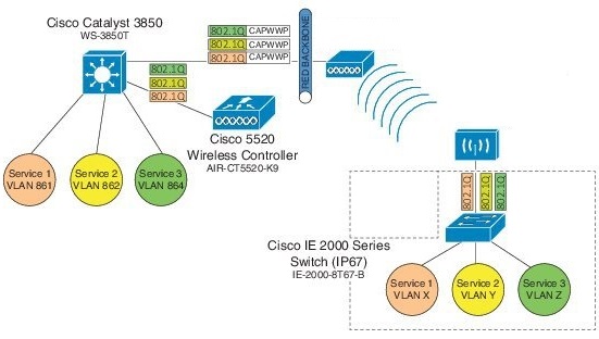
Cisco Wireless LAN Controller (WLC) Release 8.3 provides an enhancement to broadcast traffic support on multiple 802.1Q VLAN workgroup bridge (WGB) deployments that traverse mesh networks and in Local mode. Specifically, support for WGB downstream broadcasts over multiple VLANs (to differentiate and prioritize traffic); and, bridging of VLAN traffic to wired clients connected to the WGB. Applications for this functionality are commonly found in the transportation and mining industries. For more information, see CSCub87583.
Supported platforms:
-
Access point (AP) and WGB support:
-
IW3700 Series
-
1552H/SA/SD Series
-
Supported AP mode:
-
Local mode
-
Bridge mode
Prerequisites
You need to create the dynamic interfaces and bind them to the interface group before you proceed with the configuration.
-
Create the dynamic interfaces, by choosing on WLC. Add any dynamic interface that needs to support the downstream broadcast on Multiple VLANs feature into the interface group.
-
Bind the dynamic interfaces with Interface Groups, by choosing on WLC.
-
Bind the Interface Groups to WLAN. Choose WLAN. Under the specific WLAN General confirmation tab, choose the proper interface group.
Cisco Wireless Controller Configuration (CLI Only)
To enable or disable the downlink broadcast packet VLAN tagging on a WLAN (new command):
(Cisco Controller) >config wlan wgb broadcast-tagging {enable | disable} wlan-id
 Note |
This feature is disabled by default. |
 Note |
To enable this feature, you need to enable Broadcast Forwarding on WLC, by choosing and choose Enabled from the Broadcast Forwarding drop-down list. |
 Note |
To enable this feature, you should also configure the AP Multicast Mode to Multicast rather than Unicast, by clicking and choosing Multicast, and then assign Multicast Group Address. |
WGB Configuration (CLI Only)
You can configure the following on Workgroup Bridges:
-
Broadcast Tagging
-
Native VLANs
By default, Broadcast Tagging is disabled.
By default, only Native VLAN broadcasts can be forwarded to wired clients in Native VLANs.
You use the no command to disable VLAN configurations on the WGB as shown in the examples below.
 Note |
When you have multiple VLAN configurations on WGB, you need to configure the encryption cipher mode and keys as the following example shows: Then, you should configure the encryption cipher mode globally on the multicast or broadcast interface by entering the following command: |
VLAN Broadcast Tagging Configuration
-
To enable broadcast tagging on a VLAN (new command):
(WGB) (config)#workgroup-bridge unified-vlan-client broadcast-tagging
-
To disable broadcast tagging on a VLAN:
(WGB) (config)#no workgroup-bridge unified-vlan-client broadcast-tagging
 Note |
The no workgroup-bridge unified-vlan-client broadcast-tagging command will disable workgroup-bridge unified-vlan-client as well. Make sure you have workgroup-bridge unified-vlan-client configured properly to enable the multiple vlan feature. |
Reliable WGB Downstream Broadcast for Multiple VLANs
Cisco Wireless Controller (WLC) Release 8.10.130.0 provides an enhancement for the Workgroup Bridge (WGB) Downstream Broadcast On Multiple VLANs feature, which was first introduced in Release 8.3. Legacy broadcast without 802.11 ACK mechanism’s may have more chance to cause packet loss over the air. With reliable downstream broadcast feature, broadcast packet can be converted to unicast packet. Hence the Root AP will receive the ACK for converted broadcast packet and retransmit in case of missing ACK.
The converted unicast packet's header will be changed from 3-address to 4-address format. WGB’s MAC address will be used as receiver address (RA) instead of broadcast address and special multicast address with VLAN information will be used as destination address (DA). This BC2UC conversion for multiple VLAN’s is possible for WGB and its wired clients. Since the converted packet is a unicast packet, Root AP will receive the ACK for each packet and retransmit based on the retry logic by the Root AP for every ACK which is not received for this broadcast to unicast conversion.
 Note |
This enhancement is for WGB and its wired clients. It will not impact the non-WGB wireless clients. |
-
Supported AP platforms:
-
Cisco Industrial Wireless 3700 Series Access Points
-
Cisco Aironet 1570 Series Access Points
-
-
Supported WGB platforms:
-
Cisco Industrial Wireless 3700 Series Access Points
-
-
Supported AP modes:
-
Local
-
Bridge
-
As shown in the following figure, a WGB with wired clients of three different VLANs (VLAN 10, 20, and 30) joins the IOS AP wireless network. The broadcast traffic from AP to WGB will be transmitted to the clients with corresponding VLAN and retransmission will happen if traffic is lost on air.
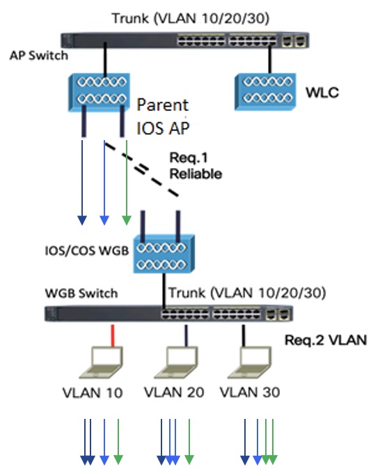
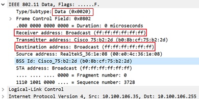
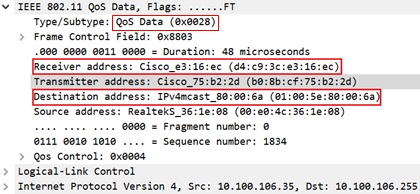
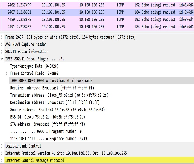
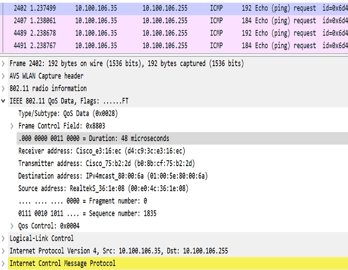
The Receiver address (RA) of legacy broadcast packet is FF:FF:FF:FF:FF:FF and there will not be any retransmission if the packet is lost in the air. The reliable downstream broadcast feature replaces this RA with WGB address and Destination address (DA) with special multicast address 01:00:5e:80:xx:xx. This will make the packet as a unicast packet and enables ACK mechanism. The packet will be retransmitted when the ACK is not received.
The multicast address 01:00:5e:80:xx:xx is introduced to transmit the VLAN information between AP and WGB. The VLAN value is embedded in 2 LSB of this multicast address. Both IOS and COS WGB support to decode this type of packet.
Root AP will make "N" copies for single broadcast packet for "N" WGBs associated to it on the specific VLAN. Also, non-converted packet will be sent for the benefit of non-WGB clients. Broadcast packets will not get converted if there is no WGBs associated on the specific VLAN.
QOS behavior:
-
The new packet is a 802.11e Qos data.
-
The 802.11e QoS priority of reliable broadcast packets will follow multicast default priority value from WLAN’s QOS configuration.
The configuration similarities and changes between Release 8.10.130.0 and Release 8.3 are as following:
-
Similarities:
-
Dynamic interface for all VLANs must be created on the WLC. It is necessary for multi-vlan support in both Release 8.10.130.0 and Release 8.3.
-
Broadcast-tagging configurations are same on WLC and WGB for both Release 8.10.130.0 and Release 8.3.
-
-
Changes:
-
Interface-group must be configured in Release 8.3 to support downstream multiple VLANs. But in 8.10.130.0, it can be supported with or without interface-group configuration on the WLAN.
-
Broadcast packets are converted to multicast packets by Root AP in Release 8.3. While in Release 8.10.130.0, broadcast packets will be converted to unicast packets by Root AP.
-
The following figures illustrate an example of 802.11 packet forwarding from VLAN 106 (0x006a). The receiver address changes from FF:FF:FF:FF:FF:FF to the MAC address of WGB Radio (d4:c9:3c:e3:16:ec), and the destination address changes from FF:FF:FF:FF:FF:FF to 01:00:5E:80:00:6a (the last two bytes in MAC address represents corresponding VLAN in hexadecimal).
Cisco Wireless Controller (WLC) Configuration
This section provides the basic configuration for AireOS controller.
-
To enable or disable reliable broadcast traffic for IOS AP, configure broadcast-tagging on the WLAN from AireOS WLC:
(Cisco Controller)> config wlan wgb broadcast-tagging <enable|disable> <wlan-id> -
To support reliable broadcast feature, basic broadcasting forwarding and global multicast feature should be enabled on WLC first. The following commands are for basic broadcast forwarding and global multicast configuration.
-
To enable global broadcast forwarding:
(Cisco Controller)> config network broadcast enable -
To configure AP multicast mode:
(Cisco Controller)> config network multicast mode multicast multicast_Group_Address
-
WGB Configuration
To support multiple VLAN on IOS WGB, the following CLI should be configured on WGB:
WGB(config)#workgroup-bridge unified-vlan-client To enable broadcast tagging on a VLAN:
WGB(config)#workgroup-bridge unified-vlan-client broadcast-tagging To disable broadcast tagging on a VLAN:
WGB(config)#no workgroup-bridge unified-vlan-client broadcast-tagging WGB will received both FF:FF:FF:FF:FF:FF and 01:00:5e:80:xx:xx packet on the native VLAN. By default, WGB will forward the normal broadcast (FF:FF:FF:FF:FF:FF) and discard the reliable broadcast (01:00:5e:80:xx:xx). If the CLI is enabled, WGB will forward the reliable broadcast (01:00:5e:80:xx:xx) to corresponding VLAN’s wired client and discard the normal broadcast (FF:FF:FF:FF:FF:FF).
Troubleshooting Reliable Broadcast
This section describes the troubleshooting of reliable broadcast on WLC, Root AP, and WGB.
-
Troubleshooting on WLC:
-
Use the show wlan <wlanid> command to check if broadcast tagging is enabled.
(WLC) > show wlan 3 Universal Ap Admin............................... Disabled Broadcast Tagging................................ Enabled -
Use debug capwap payload enable to check the mgid information sent to AP.
*spamApTask0: Feb 19 18:14:51.384: b0:8b:cf:75:b2:20 L2_MCAST_MGID_INFO : payload 0 addOrDelete 1, mgidByte[0] 0, mgidByte[1] 10 *spamApTask0: Feb 19 18:14:51.384: b0:8b:cf:75:b2:20 MCAST_MGID_INFO_PAYLOAD vapId 3, isL3Mgid FALSE, numOfMgid 1, vlanInterfaceId 10 -
Use the debug pem events command to check the association of WGB and its wired clients.
*iappSocketTask: Feb 19 14:05:38.379: 00:e0:4c:53:44:58 sending to spamAddMobile (wgb wired client) vlanId 106 mgid 11 numOfMgid 1
-
-
Troubleshooting on Root AP:
-
Use the show capwap mcast mgid all command to display L2 MGID information.
IOS-AP#show capwap mcast mgid all L2 MGID Information: L2 MGID = 0 WLAN bit map (all slots) = 0x0001 VLAN ID = 103 Slot map/tx-cnt: R0:0x0001/3446 R1:0x0001/3446 R2:0x0001/0 L2 MGID = 1 WLAN bit map (all slots) = 0x0001 VLAN ID = 0 Slot map/tx-cnt: R0:0x0001/7828 R1:0x0001/7828 R2:0x0000/0 L2 MGID = 11 WLAN bit map (all slots) = 0x0001 VLAN ID = 106 Slot map/tx-cnt: R0:0x0001/14 R1:0x0001/14 R2:0x0001/0 -
Use the show capwap mcast mgid id <mgid value> command to display the details of a specific MGID.
IOS-AP#show capwap mcast mgid id 11 L2 MGID = 11 WLAN bit map (all slots) = 0x0001 VLAN ID = 106 Slot map/tx-cnt: R0:0x0001/979 R1:0x0001/979 R2:0x0001/0 rx pkts = 979 tx packets: wlan : 0 1 2 3 4 5 6 7 8 9 10 11 12 13 14 15 slots0 : 0 0 0 0 0 0 0 0 0 0 0 0 0 0 0 0 slots1 : 979 0 0 0 0 0 0 0 0 0 0 0 0 0 0 0 slots2 : 0 0 0 0 0 0 0 0 0 0 0 0 0 0 0 0 Reliable BCAST Clients: 1 Client: d4c9.3ce3.16ec --- SlotId: 1 WlanId: 0 ConvertedBCASTtx: 263 -
Use the debug capwap mcast command to get the information of WGB and its wired clients added to the BC2UC client list.
*Dec 19 21:09:29.795: CAPWAP MCAST: capwapAddEntryToL2MgidList:Added new client d4c9.3ce3.16ec to mgid 11 list of vlan 105, Total clients in this list: 1. *Dec 19 21:10:56.491: CAPWAP MCAST: capwapAddEntryToL2MgidList:Added new client d4c9.3ce3.16ec to mgid 10 list of vlan 106 for wired client f076.1cdc.b22c, Total clients in this list: 1. -
Use debug dot11 dot11radio <0|1> trace print xmt to check the transmission of original and converted broadcast packet.
Converted Packet(4-address format):
*May  6 14:04:40.859: 613B6145 t a8.1b2s0  - 8803 000 48B89C 75B22C m01005E 16F0 361E08 q4 l92
   IP 10.100.106.255 < 10.100.106.56 f1-0-0 id 0 ttl64 sum 50AA prot 1 len 84
  ICMP ping code 0 chk F4D7, id 20765 seq 330
  CF77 B25E 0000 0000 6F17 0100 0000 0000 1011 1213 1415 1617 1819 1A1B 1C1D

Original packet (3-address format):
*May  6 14:04:40.859: 613B6204 t 18     0  - 0802 000 mFFFFFF 75B22C 361E08 C020 l92
   IP 10.100.106.255 < 10.100.106.56 f1-0-0 id 0 ttl64 sum 50AA prot 1 len 84
  ICMP ping code 0 chk F4D7, id 20765 seq 330
-
-
Troubleshooting on WGB:
-
Use the show running-config command to check the status of workgroup unified-vlan-client and workgroup-bridge unified-vlan-client broadcast-tagging.
-
Use the debug dot11 forwarding command to check whether the IOS WGB has recovered the VLAN information from converted broadcast packet.
*Sep 15 02:54:24.775: Unified WGB convert specific mcast+vlan pak to ffff.ffff.ffff:0080.483f.d5f6 on Virtual-Dot11Radio0 received, link 7, dest_vlan_id 0x402F <- 2F (Vlan id) -
Use the debug dot11 events command to check whether the IOS WGB has received the original broadcast packet and dropped.
*Feb 4 17:41:19.081: Unified WGB drop original none-tagged bcast pak from source 00e0.4c36.1e08, ethertype: 0x0800, linktype: 7 -
Use the debug dot11 dot11radio <0|1> trace print rcv command to check converted packets and original packets.
Converted Packet:
*Nov 27 15:27:23.727: CB8823A0 r  m6-2   24/128/128/128 71- 8803 02C 48B89C AD9A70 m01005E 06A0 392AC9 q4 l92
 4500 0054 0000 4000 4001 56C9 0A64 6719 0A64 67FF 0800 2E6A 1556 03BF
 B74B DE5D 0000 0000 5604 0600 0000 0000 1011 1213 1415 1617 1819 1A1B 1C1D
 1E1F 2021 2223 2425 2627 2829 2A2B 2C2D 2E2F 3031 3233 3435 3637 4860 6C3D

Original Packet:
*Nov 27 15:27:23.727: CB88246F r 18      21/128/128/128 74- 0802 000 mFFFFFF AD9A70 392AC9 4610 l92
 4500 0054 0000 4000 4001 56C9 0A64 6719 0A64 67FF 0800 2E6A 1556 03BF
 B74B DE5D 0000 0000 5604 0600 0000 0000 1011 1213 1415 1617 1819 1A1B 1C1D
 1E1F 2021 2223 2425 2627 2829 2A2B 2C2D 2E2F 3031 3233 3435 3637 0000 0000
-
Use Sniffer to capture packet over the air or on the wired side when the detailed packet information is needed.
The following figure shows the original packet details.
The following figure shows the converted packet details.
Parallel Redundancy Protocol Enhancement on AP and WGB
Cisco Wireless Release 8.4 provides the Parallel Redundancy Protocol (PRP) enhancement to improve wireless network availability for wired clients behind Workgroup Bridge (WGB), and improve the roaming performance by allowing wired clients to have dual wireless connections.
PRP allows a data communication network to prevent data transmission failures by providing two alternate paths for the traffic to reach its destination. Two Ethernet networks (LANs) with similar topology are completely separated.
A device that requires protection for data across the network connects to the two independent networks (LAN-A and LAN-B) is called a Dual Attached Node implementing PRP (DANP). A DANP source sends two frames simultaneously on both LANs. A DANP destination receives both frames and discards the duplicating. If one LAN fails, a DANP destination can still receive a frame from the other LAN.
Non-redundant endpoints in the network that attach only to either LAN-A or LAN-B are known as Singly Attached Nodes (SANs). A Redundancy Box (RedBox) is used when a single interface node must be attached to both networks. Such a node can communicate with all other nodes. The switch implements RedBox functionality is a PRP switch.
To implement the PRP function for this release, you need to connect the AP and WGB to a PRP switch. The PRP switch is to offload PRP processing. AP or WGB is to keep dual wireless connections. You can have two WGBs interconnected through an external PRP switch and wirelessly connected to a single fixed AP or two fixed APs. Two WGBs can roaming between APs. Redundant packet transmissions can be supported over either single or both 2.4 GHz and 5 GHz. The infrastructure side also needs a PRP switch for AP side.
For the application where both WGBs may roam at the same time, the roaming coordination feature is introduced to avoid roaming gaps and guarantee staggered roaming. In this release, only dual radio links roaming coordination across two WGBs is supported for roaming coordination.
Supported platforms and AP mode:
-
WLC and AP on the infrastructure side—FlexConnect AP mode (central authentication, local switching), the following IOS based platforms are supported: IW3702, 2700, 3700, and 1570 series.
-
WGB on the client side—Only supported for IW3700 Series
-
Roaming coordination—Only supported for IW3700 Series
Sample Network Configuration
General guidelines for this configuration:
-
Separation of expected redundancy in the network:
-
Traffic expecting redundancy mapped to two reserved SSID A and SSID B each with specified VLAN.
-
Each WGB is configured to connect either SSID A or SSID B.
-
Others traffic without expectation of redundancy is recommended to be mapped to other SSID.
-
-
WGB supports unified VLAN function and it is recommended that wired clients not to use VLANs assigned to SSID A or SSID B.
-
Wired clients connected to WGB are source and recipients of redundancy traffic.
The following figure shows a topology of concurrent wireless transmission via two WGBs paired with one PRP switch, commonly used in train transportation.
On the train side, the PRP switch (in this example, Cisco IE2000U) duplicates upstream packets and sends both packets simultaneously via two different ports, Gi0/1 and Gi0/2. The dual packets will pass from different WGBs or APs, to ensure that at least one packet reaches the destination. On the track side, one more PRP switch is added to each aggregating endpoint along the track. The PRP switch on the track side will remove the duplicating for upstream packets. The same redundancy for downstream packet is also available by the pair of PRP switches.
 Note |
The throughput of this solution depends on the network elements depicted in the diagram. Each element along the wired and wireless transmission path should validate its throughput to avoid being the throughput bottleneck. |

WLC Configuration (CLI Only)
To enable or disable PRP on a WLAN (new command):
(Cisco Controller)> config wlan wgb prp {enable|disable} <wlan id>
enable              Enable Parallel Redundancy Protocol (PRP) feature on a WLAN
disable             Disable Parallel Redundancy Protocol (PRP) feature on a WLAN
 Note |
This feature is disabled by default. |
This CLI will enable two WLANs to allow dual associations in flex-connect mode. It will also enable the AP to forward packets to or from WGB wired clients with double tags in flex-connect mode.
 Note |
To enable unified VLANs in the WGB, the existing command config wgb vlan enable should also be executed. You should configure the inner VLAN (VLAN for wired client) on WLC as well. |
WGB Configuration for Roaming Coordination (CLI Only)
For Parallel Redundancy Protocol (PRP), wired client traffic will be duplicated to transmit in dual radio links in two WGBs. Dual radio links without any radio link coordination have the possibility to trigger roaming at the same time, so that the traffic will be broken in a short window time.
The following figure is a typical PRP scenario of train transportation. AP like IW3702 has two physical Ethernet ports. Gig0 will be exclusively used to bridge PRP traffic. Gig1 will be used for internal communication. Gig 1 will connect to a non-PRP port on the PRP switch or connect to a peer Gig1 port directly.

Configuration of Dual Radio Coordination on Two WGBs
Follow these steps to configure dual radio coordination on two WGBs:
-
Configure service VLAN.
Use the following command to enable the service VLAN traffic that will be punted to local handling process for sub interface on Gig0 or Gig1.
WGB(config)# workgroup-bridge service-vlan <vlan id> -
Configure peer coordinator address.
Use the following commands to set peer coordinator address and create the coordination communication process. For example, if you have configured the service VLAN to 50, you should configure the local/peer coordinator address under sub interface 50.
WGB(config)# interface GigabitEthernet1.50 WGB(config-subif)# encapsulation dot1q 50 WGB(config-subif)# ip coordinator peer-addr <addr> -
Configure dot11 radio coordinator on two WGBs.
Use the following commands to create dot11 coordinator process, and enable dot11 roaming coordinator service on radio 0 or radio 1.
WGB(config)# dot11 coordinator uplink single [radio 0|radio 1] -
Configure dot11 coordination roaming waiting timer.
Use the following command to set the dot11 coordination roaming waiting timer. The default is 100ms.
WGB(config)# dot11 coordinator timeout roam-wait [value] -
Configure Dot11 roaming coordination bypass.
Use the following command to bypass roaming coordination decision on WGB. When configured, it is used to collect WGB’s roaming conflict statistics, and will not affect the current roaming behavior.
WGB(config)# dot11 coordinator bypass -
Configure to avoid bridge loop.
Wired network on WGB side can introduce a bridge loop if you connect the Gig1 port of WGBs directly or via a switch. The following sample configurations can avoid the bridge loop.

Note
The coordination traffic is forwarded on service VLAN and will not be blocked.
-
To avoid bridge loop when connecting the Gig1 port of WGBs directly, configure the following on both WGBs:
WGB(config)# access-list 700 deny 0000.0000.0000 ffff.ffff.ffff WGB(config)# interface gigabitEthernet 1 WGB(config-if)# l2-filter bridge-group-acl WGB(config-if)# bridge-group 1 WGB(config-if)# bridge-group 1 output-address-list 700 -
To avoid traffic loop when connecting two WGBs via a switch, configure the following on the switch port:
interface GigabitEthernet0/3
switchport trunk allowed vlan 50
switchport mode trunk

interface GigabitEthernet0/4
switchport trunk allowed vlan 50
switchport mode trunk
-
WLC Configuration
 Note |
For more information about WLC configuration for FlexConnect, see the FlexConnect Chapter in the Cisco Wireless Controller Configuration Guide. |
Follow these steps to configure the wireless controller for FlexConnect:
-
Create two WLANs with the SSID PRP1 and PRP2.
-
Enable local switching for each WLAN.
 Note |
For any wired client within the service vlan, you need to create a corresponding dynamic interface with the same service vlan on WLC. |
Configuration of AP
-
Configure AP to FlexConnect mode and join WLC.
-
Enable VLAN support on each AP, and make sure PRP SSID is included.
Configuration of WGBs
-
WGB1 Configuration
hostname WGB1 dot11 ssid PRP1 vlan 801 authentication open interface Dot11Radio1 no ip address ssid PRP1 antenna gain 0 stbc beamform ofdm station-role workgroup-bridge ! interface Dot11Radio1.800 encapsulation dot1Q 800 bridge-group 2 bridge-group 2 spanning-disabled ! interface Dot11Radio1.801 encapsulation dot1Q 801 native bridge-group 1 bridge-group 1 spanning-disabled ! interface GigabitEthernet0 no ip address duplex auto speed auto ! interface GigabitEthernet0.800 encapsulation dot1Q 800 bridge-group 2 ! interface GigabitEthernet0.801 encapsulation dot1Q 801 native bridge-group 1 ! interface BVI1 mac-address 4c00.821a.c0b0 ip address dhcp ipv6 address dhcp ipv6 address autoconfig ipv6 enable ! bridge 1 route ip ! workgroup-bridge unified-vlan-client -
WGB2 Configuration
hostname WGB2
dot11 ssid PRP2
   vlan 802
   authentication open
interface Dot11Radio1
 no ip address
 !
 ssid PRP2
 !
 antenna gain 0
 stbc
 beamform ofdm
 station-role workgroup-bridge
!
interface Dot11Radio1.800
 encapsulation dot1Q 800
 bridge-group 2
 bridge-group 2 spanning-disabled
!
interface Dot11Radio1.802
 encapsulation dot1Q 802 native
 bridge-group 1
 bridge-group 1 spanning-disabled
!
interface GigabitEthernet0
 no ip address
 duplex auto
 speed auto
!
interface GigabitEthernet0.800
 encapsulation dot1Q 800
 bridge-group 2
!
interface GigabitEthernet0.802
 encapsulation dot1Q 802 native
 bridge-group 1
!
interface BVI1
 mac-address f872.eae4.a4d8
 ip address dhcp
 ipv6 address dhcp
 ipv6 address autoconfig
 ipv6 enable
bridge 1 route ip
workgroup-bridge unified-vlan-client
Aggregated Switch Configuration
Agg-SW# show run int fa 1/0/1
description ***AP1***
 switchport trunk encapsulation dot1q
 switchport trunk native vlan 201
 switchport trunk allowed vlan 201,801,802
 switchport mode trunk
end


Agg-SW#show run int fa 1/0/3
Building configuration...


Current configuration : 196 bytes
!
interface FastEthernet1/0/3
 description ***AP2***
 switchport trunk encapsulation dot1q
 switchport trunk native vlan 201
 switchport trunk allowed vlan 201,801,802
 switchport mode trunk
end

Agg-SW# show run int fa 1/0/7
Building configuration...


Current configuration : 178 bytes
!
interface FastEthernet1/0/7
 description ***PRP-Track-SW***
 switchport access vlan 801
 switchport trunk encapsulation dot1q
 switchport mode dot1q-tunnel
 no cdp enable
end


Agg-SW# show run int fa 1/0/8
Building configuration...


Current configuration : 178 bytes
!
interface FastEthernet1/0/8
 description ***PRP-Track-SW***
 switchport access vlan 802
 switchport trunk encapsulation dot1q
 switchport mode dot1q-tunnel
 no cdp enable
PRP Switch Configuration
interface PRP-channel1
 switchport mode trunk
interface GigabitEthernet0/1
 switchport mode trunk
 no ptp enable
 no cdp enable
 prp-channel-group 1
!
interface GigabitEthernet0/2
 switchport mode trunk
 no ptp enable
 no cdp enable
 prp-channel-group 1
 Note |
For the PRP configurations on the Cisco IE switches, refer to Parallel Redundancy Protocol Software Configuration Guide for Industrial Ethernet 2000U Series Switches. |
Verifying the PRP Configurations
Follow these steps to verify the PRP configurations:
Before you begin
-
Create an SVI interface on the train side PRP switch with service vlan: 800.
-
Configure the SVI interface on the track side PRP switch with service vlan: 800, and create the DHCP pool.
Procedure
| Step 1 |
On the train side PRP switch, use the following command to check whether an IP address has been assigned to Vlan 800 from the DHCP pool on the track side. Example: |
| Step 2 |
On the track side PRP switch, use the following command to display ingress packet statistics. In this example, LAN A and LAN B both have one packet. Example: |
| Step 3 |
On the train side PRP switch, ping the track side with the following command, to send 5 packets from the train to the track side: Example: |
| Step 4 |
On the track side PRP switch, use the following command to display the number of packets that LAN A and LAN B have received, and the number of duplicated packets that have been discarded. In this example, after receiving 5 packets, both LAN A and LAN B have 6 packets in total. Example: |
Viewing the Status of Workgroup Bridges (GUI)
Procedure
| Step 1 |
Choose Monitor > Clients to open the Clients page. The WGB text box on the right side of the page indicates whether any of the clients on your network are workgroup bridges. |
| Step 2 |
Click the MAC address of the desired client. The Clients > Detail page appears. The Client Type text box under Client Properties shows “WGB” if this client is a workgroup bridge, and the Number of Wired Client(s) text box shows the number of wired clients that are connected to this WGB. |
| Step 3 |
See the details of any wired clients that are connected to a particular WGB as follows: |
Viewing the Status of Workgroup Bridges (CLI)
Procedure
| Step 1 |
See any WGBs on your network by entering this command: show wgb summary |
| Step 2 |
See the details of any wired clients that are connected to a particular WGB by entering this command: show wgb detail wgb _mac_address |
Debugging WGB Issues (CLI)
Before you begin
-
Enable debugging for IAPP messages, errors, and packets by entering these commands:
-
debug iapp all enable —Enables debugging for IAPP messages.
-
debug iapp error enable —Enables debugging for IAPP error events.
-
debug iapp packet enable —Enables debugging for IAPP packets.
-
-
Debug an roaming issue by entering this command:
debug mobility handoff enable
-
Debug an IP assignment issue when DHCP is used by entering these commands:
-
debug dhcp message enable
-
debug dhcp packet enable
-
-
Debug an IP assignment issue when static IP is used by entering these commands:
-
debug dot11 mobile enable
-
debug dot11 state enable
-
 Feedback