Access Point Views, Ports, and Connectors
The AP has multiple options that you can use to power the AP. For information about connectors and ports for the AP models, see Connectors and Ports on the AP.
Environment Sensors
The AP has inbuilt environment sensors that work with Cisco Spaces (earlier known as Cisco DNA Spaces). There are two visible vents at the top of the AP. The sensors measure the following environment parameters:
-
Ambient air temperature
-
Air quality (Total Volatile Organic Compounds [TVOC])
-
Humidity
Connectors and Ports on the AP
The following figures show the available ports on the AP:
C9136I Face View
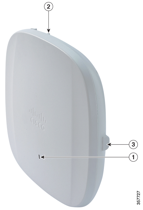
|
1 |
Status LED |
|
2 |
Location of the ports and connectors on the head of the AP. |
|
3 |
USB 2.0 port |
C9136I Top View
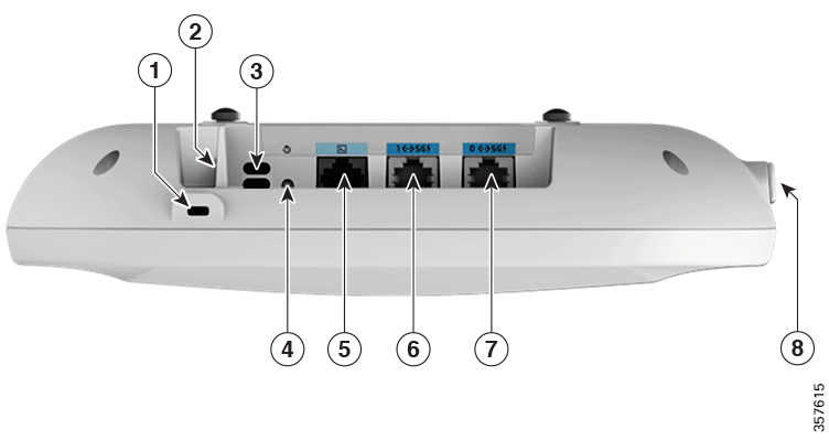
|
1 |
Kensington lock slot |
5 |
RJ-45 console port |
|
2 |
Security hasp for padlocking AP to the mounting bracket |
6 |
5-GbE port 1 |
|
3 |
Environment Sensor vents |
7 |
5-GbE port 0 |
|
4 |
Mode button For information about how to use the Mode button, see Using the Mode Button |
8 |
USB 2.0 port |


 Feedback