Servicing the GPU Module
The X10c front mezzanine GPU module contains U.2 drives, GPU cables, GPU cages, and GPU cards as field-replaceable components.
To service these components, see the following topics:
Removing a Compute Node Cover
To remove the cover of the compute node, follow these steps:
Procedure
|
Step 1 |
Press and hold the button down. |
|
Step 2 |
While holding the back end of the cover, slide it back, then pull it up to lift the top cover off of the compute node. By sliding the cover back, you enable the front edge to clear the metal lip on the rear of the front mezzanine module. |
Replacing a GPU Cage
The GPU cage is an adapter card that provides two slots for GPUs cards. GPU cages provide the mechanical housing for individual GPU cards. Removing the GPU cage is a prerequisite for removing or installing a GPU card.
Use the following procedures to replace a GPU cage.
Cabling Considerations
Refer to the following illustration while reviewing these cabling considerations.
 Note |
In the following illustration, the front mezzanine GPU module is upside down to easily show the cables. |
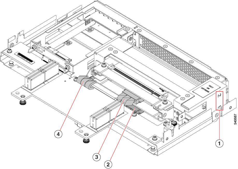
|
1 |
Front Mezzanine GPU Module Slot Identifier, 1 or 2 |
2 |
MCIO cable, GPU cage end This cable connects to front Mezzanine GPU Module Slot 1 |
|
3 |
MCIO cable and connector, GPU cage end This cable connects to front Mezzanine GPU Module Slot 2 |
4 |
MCIO cable, front mezzanine PCB end. |
If you are removing the entire GPU cage, be aware of the following considerations.
 Note |
If you are removing or installing the GPU cards themselves, these considerations do not apply. |
-
Each GPU slot has an MCIO cable. One end of the cable connects to the GPU cage, and the other end connects to a socket on the mezzanine PCB.
-
The slots on the Front mezzanine GPU module numbered 1 or 2. Although cables and connectors are not labeled, you can use these slot numbers to help identify which cable must be connected to which front mezzanine slot.

Note
The GPU card slots are also numbered 1 or 2.
-
Cables are not labeled, so make sure that you don't mix up the connections, such as connect the cable for slot 2 to slot 1.
-
Before disconnecting cables, you will find it helpful to mark which cable connects to GPU 1 and which cable connects to GPU 2.
-
If you are working with both GPU cables, do the following to allow more room for your fingers:
-
Disconnect slot 2's cable first, then slot 1's cable.
-
Connect slot 1's cable first, then slot 2's cable.
-
-
When you are installing cables, make sure that you route them so that they do not pinch, bind, or interfere with the removal or installation of other parts.
-
When installing a GPU cage, always connect the GPU-cage end of the cable first, then connect the mezzanine PCB-end of the cable.
-
When removing a GPU cage, always disconnect the PCB-end of the cable first before detaching the GPU-cage end of the cable.
-
In most cases, you can leave the cables connected at the front mezzanine end and disconnect cables from just the GPU end. However, if you must disconnect the front mezzanine end of the cable, the MCIO connectors are labeled on the front mezzanine PCB to help identify how to reconnect the cables.

1
Front Mezzanine PCB connector for MCIO cable 1
2
Front Mezzanine PCB connector for MCIO cable 2
Removing the GPU Cage
The GPU cage houses up to two GPUs. Use the following task to remove a GPU cage.
Procedure
|
Step 1 |
If you have not done so already, remove the front mezzanine GPU module from the server. |
||
|
Step 2 |
Place the front mezzanine GPU module upside down on an ESD-safe work surface. |
||
|
Step 3 |
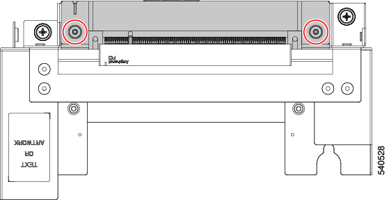
Locate the 2 Phillips-head screws at the rear of the GPU cage.
|
||
|
Step 4 |
Using a #2 Phillips screwdriver, remove the 2 Phillips-head screws from the GPU cage. |
||
|
Step 5 |
Slide the GPU cage towards the rear of the front mezzanine GPU board. |
||
|
Step 6 |
Holding the front edge of the GPU cage (the end opposite the 2 Phillips0-ead screws you loosened), rotate the GPU cage 90 degrees so that its vertical. The front of the cage has a "T" nut as a retention feature. If you cannot rotate the GPU cage up, it is probably obstructed by the "T" nut. Repeat the previous step until the GPU cage rotates easily.
 |
What to do next
Choose the appropriate option.
Installing a GPU Cage
Use the following task to reinsert a GPU cage into the front mezzanine GPU module.
Procedure
|
Step 1 |
Rotate the GPU cage down until it lies flat on the sheet metal as far away from the GPU module's front panel as possible. |
|
Step 2 |
Carefully slide the GPU cage toward the front of the front mezzanine GPU module until the rear captive screws line up with their screw holes. When properly installed, the front of the GPU cage is captured by "T" nuts. |
|
Step 3 |
Lift up on the GPU cage to verify that it is captured by the "T" nuts. If you cannot lift the GPU cage, it is correctly installed. |
|
Step 4 |
Using a #2 Phillips screwdriver, tighten each of the captive screws to 5 in-lb of torque. |
|
Step 5 |
Replace the compute node's top cover and reinsert the compute node into the server chassis. |
Replacing a GPU Card
A maximum of two GPU cards (UCSX-GPU-T4-MEZZ) are supported in the GPU cage in slots 1 or 2. Slots are numbered on the side of the GPU cage.
 Note |
Do not operate the compute node with an empty GPU card slot. |
Use the following tasks to replace a GPU card.
GPU Card Guidelines and Restrictions
Be aware of the following guidelines and restrictions for GPU cards:
-
Do not operate the compute node with an empty GPU card slot.
-
In a one GPU system, it is a best practice to have the GPU in slot 1.
-
If your front mezzanine GPU module has only one GPU card, the other GPU slot must contain a GPU filler blank (UCSX-GPUFM-BLK). If you ordered your GPU module with only one GPU, the filler blank is preinstalled at the factory.
-
GPU slots are keyed so that they can accept only the supported GPU (UCSX-GPU-T4-MEZZ).

Caution
Cisco offers multiple models of Cisco T4 GPU, but they are not all interchangeable between the different Cisco products. For the Cisco X10c Front Mezzanine GPU Module, the only Cisco T4 GPU supported is UCSX-GPU-T4-MEZZ, which has a custom heatsink. You can identify this GPU by the M3 screw on the GPU bracket, which is a different screw from any other Cisco T4 GPU. Because of the heatsink and screw, the UCSX-GPU-T4-MEZZ is supported only on the front mezzanine GPU module. Do not attempt to install the UCSX-GPU-T4-MEZZ in any other Cisco product.
-
Always follow guidance on any service label or warning sticker physically installed on the GPU and front mezzanine module.
Removing a GPU Card
Use this task to remove a GPU from the GPU cage.
Procedure
|
Step 1 |
When the GPU cage is vertical, use a #2 Phillips screwdriver to loosen the captive Phillips-head screw at the bottom of the GPU slot. |
|
Step 2 |
Grasping the bracket and the opposite edge of the GPU, slide the GPU straight up to remove it from the GPU cage.  |
What to do next
Choose the appropriate option.
Installing a GPU Card
Use this task to install a supported GPU card (UCSX-GPU-T4-MEZZ) in the GPU slots in the GPU cage.
Procedure
|
Step 1 |
Using the GPU card's bracket, align the GPU with its slot in the GPU cage. Each slot in the GPU cage has a notch that catches the GPU bracket. |
||
|
Step 2 |
Slide the GPU into its socket, making sure that the PCI connector seats into the socket inside the GPU cage.
|
||
|
Step 3 |
Using a #2 Phillips screwdriver, tighten the captive Phillips-head screw to 5 in-lbs of torque. |
||
|
Step 4 |
If needed, repeat this process to install another GPU card in a different GPU slot.  |
What to do next
Removing a GPU Filler Blank
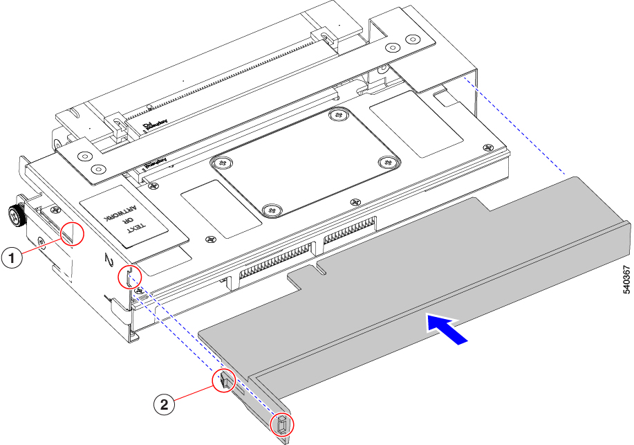
Each GPU filler blank has a retaining clip on each side of the blank. The retaining clips hook behind the sheet metal of the GPU cage to secure the filler panel in place.
Use the following task to remove a GPU filler blank.
 Note |
Do not operate the front mezzanine GPU module with an empty GPU slot. |
Procedure
|
Step 1 |
Locate each of the retaining clips on the side of the GPU cage (1). |
|
Step 2 |
Press both of the filler blank's retaining clips inward until they clear the sheet metal of the GPU cage. |
|
Step 3 |
Grasping the filler blank, slide it straight up to remove it from the slot in the GPU cage (2).
|
What to do next
Insert a GPU card in the empty GPU slot. See Installing a GPU Card.
Installing a GPU Filler Blank
If your front mezzanine GPU module has only one GPU, it must be installed in the GPU 1 slot. The GPU 2 slot must contain a GPU filler blank.
GPU filler blank has a flexible retention clip that meets the sheet metal of the GPU cage to securely hold the blank in the slot. Use the following task to install a GPU filler blank.
Procedure
|
Step 1 |
Locate the retaining clips on the filler blank (2, in the illustration). Each side of the filler blank has a retaining clip. |
|
Step 2 |
Grasping the filler blank by the bracket, align the filler blank with the GPU slot. |
|
Step 3 |
Holding the filler blank level, slide it into the GPU slot until the retaining clips fit into place behind the sheet metal wall of the GPU cage (1).
|
|
Step 4 |
Make sure that the tab on the filler bracket sits flush in the GPU slot. |
What to do next
Reinsert the GPU cage onto the front mezzanine GPU module. Installing a GPU Cage
Replacing a Drive
The front mezzanine GPU module supports up to two U.2 NVMe drives. Each drive is front-loading into the front of the module.
Use the following tasks to replace a U.2 drive.
NVMe SSD Requirements and Restrictions
For 2.5-inch NVMe SSDs, be aware of the following:
-
NVMe 2.5 SSDs support booting only in UEFI mode. Legacy boot is not supported.
UEFI boot mode can be configured through the Boot Order Policy setting in the Server Policy supported by Cisco Intersight Managed Mode (IMM). For instructions about setting up UEFI boot mode through Cisco IMM, go to:
-
NVMe PCIe SSDs cannot be controlled with a SAS RAID controller because NVMe SSDs interface with the server via the PCIe bus.
-
UEFI boot is supported in all supported operating systems.
Hot Plug Considerations
Enabling Hot Plug Support
Surprise and OS-informed hot plug is supported with the following conditions:
-
VMD must be enabled to support hot plug. VMD must be enabled before installing an OS on the drive.
-
If VMD is not enabled, surprise hot plug is not supported, and you must do OS-informed hot plug instead.
-
VMD is required for both surprise hot plug and drive LED support.
Removing a Drive
Use this task to remove a U.2 NVMe drive from the front mezzanine GPU module.
 Caution |
Do not operate the system with an empty drive bay. If you remove a drive, you must reinsert a drive or cover the empty drive bay with a drive blank. |
Procedure
|
Step 1 |
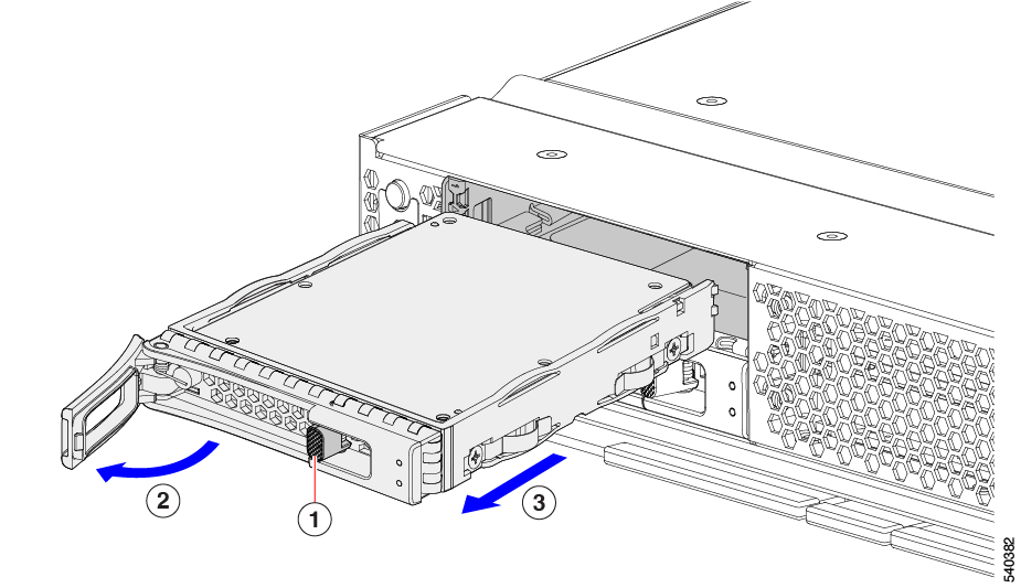
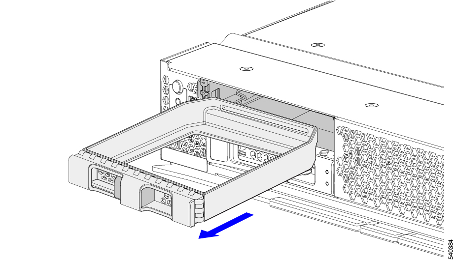
Push the release button to open the ejector, and then pull the drive from its slot.
 |
||
|
Step 2 |
Place the drive on an antistatic mat or antistatic foam if you are not immediately reinstalling it in another compute node. |
||
|
Step 3 |
Install a drive blanking panel to maintain proper airflow and keep dust out of the drive bay if it will remain empty. |
What to do next
Cover the empty drive bay. Choose the appropriate option:
Installing a Drive
 Caution |
For hot installation of drives, after the original drive is removed, you must wait for 20 seconds before installing a drive. Failure to allow this 20-second wait period causes the management software to display incorrect drive inventory information. If incorrect drive information is displayed, remove the affected drive(s), wait for 20 seconds, then reinstall them. |
To install a U.2 NVMe drive, follow this procedure:
Procedure
|
Step 1 |
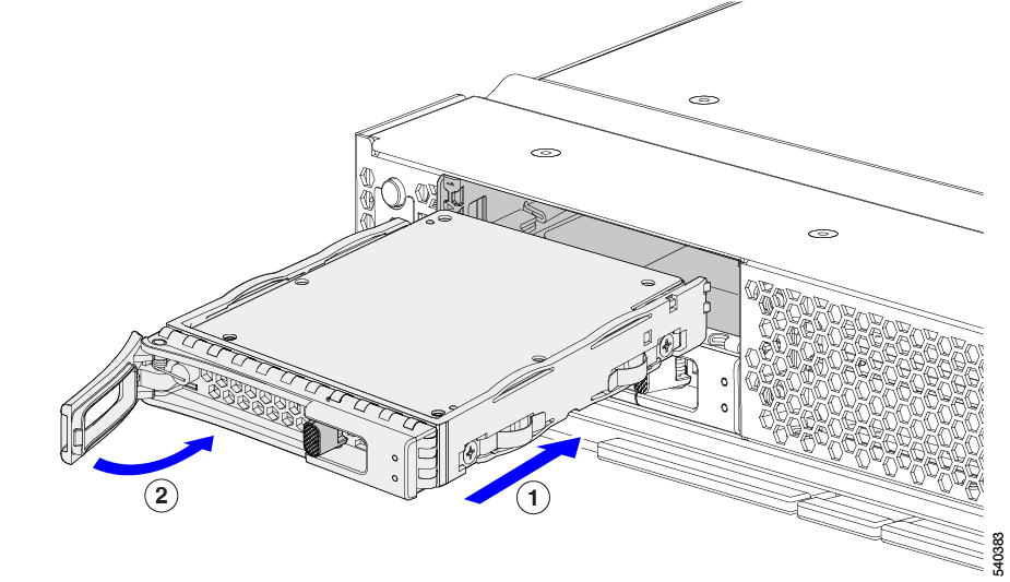
Place the drive ejector into the open position by pushing the release button. |
|
Step 2 |
Gently slide the drive into the empty drive bay until it seats into place. |
|
Step 3 |
Push the drive ejector into the closed position. You should feel the ejector click into place when it is in the closed position.
|
Removing a Drive Blank
A maximum of U.2 NVMe drives are contained in the front mezzanine storage module. If your front mezzanine module has fewer than two U.2 drives, you must install drive blank panels in the empty drive bays.
 Note |
Do not operate a front mezzanine GPU module that has empty drive bays without a drive blank panel. |
Use this procedure to remove a drive blank.
Procedure
|
Step 1 |
Grasp the drive blank handle. |
|
Step 2 |
Slide the drive blank out of the slot.
|
What to do next
Cover the empty drive bay. Choose the appropriate option:
Installing a Drive Blank
Use this task to install a drive blank.
Procedure
|
Step 1 |
Align the drive blank so that the sheet metal is facing down. |
|
Step 2 |
Holding the blank level, slide it into the empty drive bay.
|






 Feedback