The following is a partial list of memory usage and population guidelines. For detailed information about memory usage and
population, download the Cisco UCS C220/C240/B200 M6 Memory Guide.

Caution
|
Only Cisco memory is supported. Third-party DIMMs are not tested or supported.
|
This compute node contains 32 DIMM slots—16 per CPU
Memory Considerations
-
All DIMMs must be all DDR4 DIMMs.
-
x4 DIMMs are supported.
-
DIMMs must be loaded lowest number slot first.
-
Memory ranks are 64- or 72-bit chunks of data that each memory channel for a CPU can use. Each memory channel can support
a maximum of 8 memory ranks. For quad-rank DIMMs, a maximum of 2 DIMMs are supported per channel (4 ranks * 2 DIMMs).
-
Mixed ranks of DIMMs are allowed in the same channel, but you must populate higher quantity rank DIMMs in the lower numbered
slots.
-
All slots must be populated with either a DIMM or a DIMM blank.
-
Validation on all permutations for 100% test
coverage is not supported. See the DIMMs
Population Order table for supported
configurations.
-
It’s important to balance population between
each CPU and each memory controller in each CPU to
optimize memory capacity, except for single DIMM
per CPU configurations, which should be loaded
with the higher capacity DIMM on CPU1.
DIMM Identification
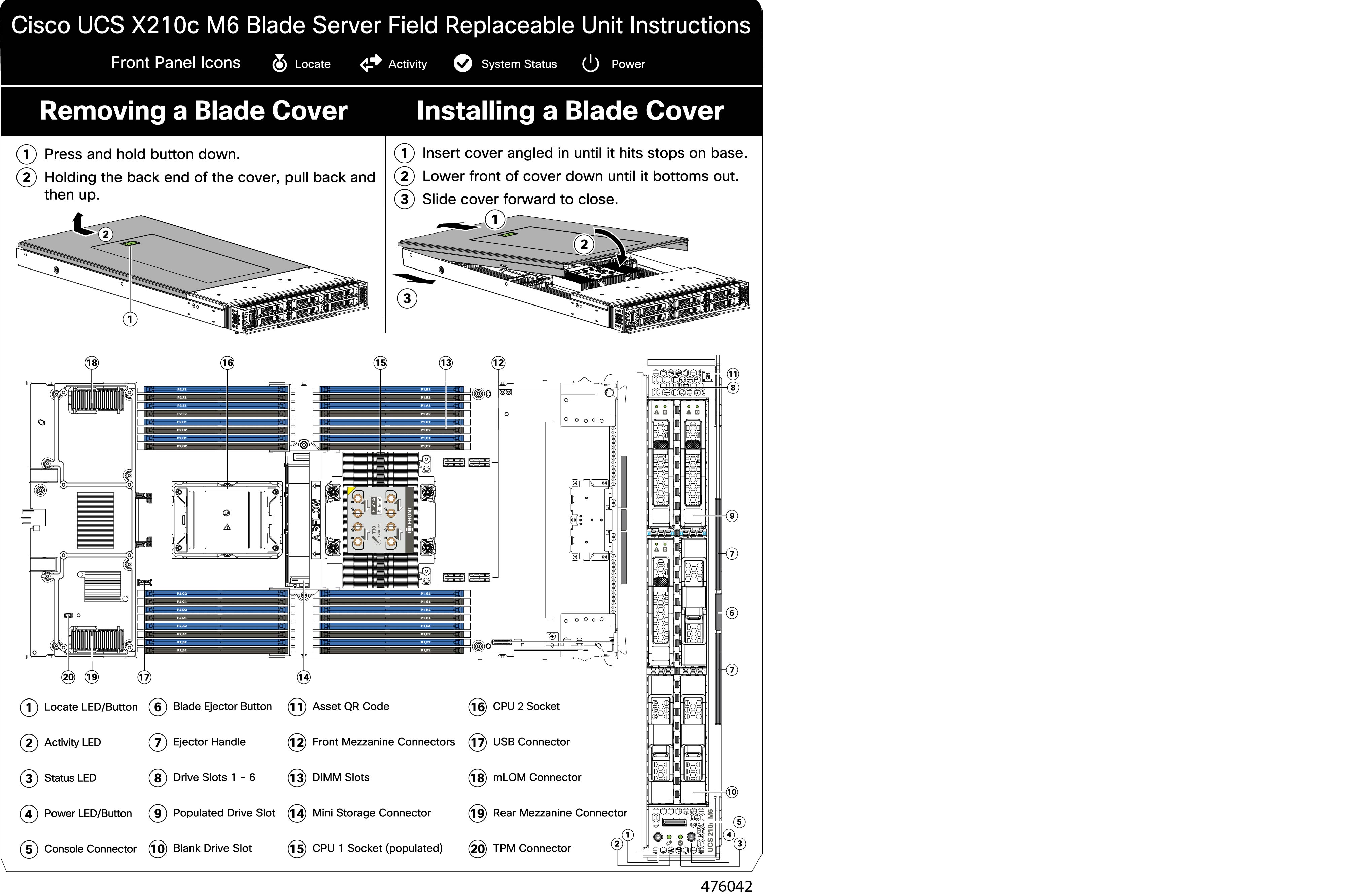
To assist with identification, each DIMM slot displays its memory processor and slot ID on the motherboard. For example, P1
A1 indicates slot A1 for processor 1.
Also, you can further identify which DIMM slot connects to which CPU by dividing the blade in half vertically.
For each CPU, each set of 16 DIMMs is arranged into 8 channels, where each channel has two DIMMs. Each DIMM slot is numbered
1 or 2, and each DIMM slot 1 is blue and each DIMM slot 2 is black. Each channel is identified by two pairs of letters and
numbers where the first pair indicates the processor, and the second pair indicates the memory channel and slot in the channel.
-
Channels for CPU 1 are P1 A1 and A2, P1 B1 and B2, P1 C1 and C2, P1 D1 and D2, P1 E1 and E2, P1 F1 and F2, P1 G1 and G2, P1
H1 and H2.
-
Channels for CPU 2 are P2 A1 and A2, P2 B1 and B2, P2 C1 and C2, P2 D1 and D2, P2 E1 and E2, P2 F1 and F2, P2 G1 and G2, P2
H1 and H2.
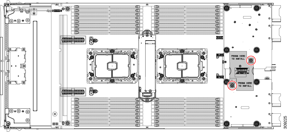
The following illustration shows the memory slot and channel IDs.

Memory Population Order
Memory slots are color coded, blue and black. The color-coded channel population order is blue slots first, then black.
For optimal performance, populate DIMMs in the order shown in the following table, depending on the number of CPUs and the
number of DIMMs per CPU. If your server has two CPUs, balance DIMMs evenly across the two CPUs as shown in the table.

Note
|
The table below lists recommended configurations.
Using 3, 5, 7, 9, 10, 11, or 13-15 DIMMs per CPU
is not recommended. Other configurations results
in reduced performance.
|
The following table shows the memory population order for DDR4 DIMMs.
Table 1. DIMMs Population Order
|
Number of DDR4 DIMMs per CPU (Recommended Configurations)
|
Populate CPU 1 Slot
|
Populate CPU2 Slots
|
|
P1 Blue #1 Slots
P1_slot-ID
|
P1 Black #2 Slots
P1_slot-ID
|
P2 Blue #1 Slots
P2_slot-ID
|
P2 Black #2 Slots
P2_slot-ID
|
|
1
|
A1
|
-
|
A1
|
-
|
|
2
|
A1, E1
|
-
|
A1, E1
|
-
|
|
4
|
A1, C1, E1, G1 |
-
|
A1, C1, E1, G1 |
-
|
|
6
|
A1, C1, D1, E1, G1, H1
|
-
|
A1, C1, D1, E1, G1, H1
|
-
|
|
8
|
A1, B1, C1, D1, E1, F1, G1, H1
|
-
|
A1, B1, C1, D1, E1, F1, G1, H1
|
- |
|
12
|
A1, C1, D1, E1, G1, H1
|
A2, C2, D2, E2, G2, H2
|
A1, C1, D1, E1, G1, H1
|
A2, C2, D2, E2, G2, H2
|
|
16
|
All populated (A1 through H1)
|
All populated (A2 through H2)
|
All populated (A1 through H1)
|
All populated (A2 through H2)
|

Note
|
For configurations with 1, 2, 4, 6 and 8 DIMMs,
install higher capacity followed by lower capacity
DIMMs in alternating fashion. For example, the 4
DIMMs configuration is installed with 64GB on A1,
E1 on both CPUs and 16GB on C1, G1 on both
CPUs.
For configurations with 12 and 16 DIMMs, install
all higher capacity DIMMs in blue slots and all
lower capacity DIMMs in black slots.
|
DIMM Slot Keying Consideration
DIMM slots that connect to each CPU socket are oriented 180 degrees from each other. So, when you compare the DIMM slots for
CPU 1 and the DIMM slots for CPU 2, the DIMMs do not install the same way. Instead, when you install DIMM attached to both
CPUs, the DIMM orientation must change 180 degrees.
To facilitate installation, DIMMs are keyed to ensure correct installation. When you install a DIMM, always make sure that
the key in the DIMM slot lines up with the notch in the DIMM.

Caution
|
If you feel resistance while seating a DIMM into its socket, do not force the DIMM or you risk damaging the DIMM or the slot.
Check the keying on the slot and verify it against the keying on the bottom of the DIMM. When the slot's key and the DIMM's
notch are aligned, reinstall the DIMM.
|





















 )
)
 )
)
 )
)
 Feedback