Implementation Options

This section contains the following:

Power over Ethernet

Power over Ethernet (PoE) is typically used to power up Access points, IP Cameras and IP Phones connected to the device's Ethernet ports.

The ESS3300 supports Power over Ethernet (PoE and PoE+) on up to 16 ports with visibility and management from Cisco IOS-XE Software.


Important


The ESS3300 uses a SPI bus based device from Microsemi / Microchip PD69208M as the PoE controller. Failure of the integrator to use this controller will result in IOS-XE not recognizing the device.

Note


The Powered Device (PD) will be detected if it is IEEE-compliance or a Cisco standard device. Support for CDP and LLDP is available for power negotiation, and must be enabled on the ESS3300.

Note


CDP and/or LLDP must be enabled on the ESS3300, and the PD must support CDP and/or LLDP for the device to be able to negotiate power levels between 15 and 30 watts.

Note


In ESS-3300 PoE devices, when a Powered Device (PD) is connected, if the switch or port lacks the power to bring up the PD, the port provides whatever power is available in the device. If the PD can operate with the given power, the port indicates the class for which the power is allocated. If the supplied power is insufficient to power up the PD, the port switches to power denial.


Note


If the port is configured with a static value in the CLI, such as power inline static max , and the connected PD requires more power than configured, the port becomes error-disabled.


Device Detection and Power Allocation

The switch will detect a Cisco Pre-standard or an IEEE-compliant PD when the PoE is enabled and the connected device is not being powered by an AC adapter.

After device detection, the switch determines the power requirements based on power classification class. Depending on the available power in the power budget, the switch determines if a port can be powered. The switch initially allocates this power when it detects and powers the device. Power negotiation using CDP/LLDP protocols happens thereafter. Maximum power budget for 4 LAN ports combined at any time is 30W x4 = 120W. On reload the PoE ports are powered down.(i.e they are powered down at rommon stage).

Power Management

Limit the PoE budget to prevent excess power consumption that may exceed the capacity of the power source.

To limit the PoE budget, configure the overall PoE budget using the power inline wattage max <watts-for-PSU> command in global configuration mode.


Note


The switch needs a minimum wattage of power to run efficiently. The power budget for PoE is calculated as the total power of the PSU minus the minimum wattage. For example, if the PSU can provide 170W of power and needs a minimum of 20W of power to run the switch, then the maximum PoE budget that can be configured is 150W.

Command Line Interface

This section describes the CLI to use for configuring and displaying PoE.

Before you configure Power over Ethernet (PoE), note the following:

  • show inventory and show diag commands will not display details of the vendor/system integrator's PoE controller.

  • show run command will not reflect the current PoE configuration.

  • On connecting a PD, power negotiation happens almost instantly. However, it takes 3-5 minutes to reflect accurate statistics using show power inline

  • The default software mode is PoE and not PoE+ to prevent overdraw.

  • There is limited support for LLDP-MED and LLDP-MDI.


Note


Implementation of PoE is a partner option. The integrator is responsible for proper implementation into the finished product, therefore, it may or may not be available.

To configure auto or off:


power inline auto | never
 
Configuration example:
switch#config terminal
switch#interface g0/1/<1,2,3,4>
switch(config-if)#power inline {auto|never} 

To enable CDP:

switch#config terminal
switch(config)#cdp run
switch(config#exit

To enable LLDP:

switch#config terminal
switch(config)#lldp run
switch(config#exit

To Verify your configuration:

switch#show power inline
Available:120.0(w)  Used:21.1(w)  Remaining:98.9(w)

Interface Admin  Oper       Power   Device              Class Max
                            (Watts)                            
--------- ------ ---------- ------- ------------------- ----- ----
Gi0/1/0   auto   on         14.7    IP Phone 8865       4     30.0 
Gi0/1/1   auto   on         6.3     IP Phone 8811       2     30.0 
Gi0/1/2   auto   off        0.0     n/a                 n/a   30.0 
Gi0/1/3   auto   off        0.0     n/a                 n/a   30.0 
switch#

To show power on a particular interface:


switch#show power inline {interface-id}

Displays PoE status for a switch for the specified interface.


show power inline interface-id detail
 

To show power consumption:

switch#show power
Main PSU :
    Total Power Consumption from 3.3V Line : 0.36
    Total Power Consumption from 5V Line : 6.20
    Configured Mode : N/A
    Current runtime state same : N/A
    PowerSupplySource : External PS
POE Module :
    Configured Mode : N/A
    Current runtime state same : N/A
    Total power available : 120 Watts
switch#

The list of commands for debugging PoE follows:

Command

Description

Debug ilpower controller

Display PoE controller debug messages

Debug ilpower event

Display PoE event debug messages

Debug ilpower port

Display PoE port manager debug messages

Debug ilpower powerman

Display PoE power management debug messages

Debug ilpower cdp

Display PoE CDP debug messages

Debug ilpower registries

Display PoE registries debug messages

Debug ilpower scp

Display PoE scp debug messages

Working with the External USB3.0

The ESS3300 provides access to a single USB 3.0 Type A device.

External USB3.0

The following details are important when working with an external USB device:

  • The USB is for storage only and can be gracefully mounted/unmounted using IOS CLI.

  • The USB is accessible in ROMMON, IOS, and IOx applications.

  • USB device must have single partition, and in ext2, Fat16, or Fat32 format only.

  • The user can copy files between usbflash0: to/from flash:/bootflash:, msata:

  • In both ROMMON and IOS, use dir usbflash0: to view USB:


Caution


No hot-plug support in rommon mode. On insertion of USB, reboot (rommon1>reset) to view usb.

Caution


Cisco USBs are strongly recommended and are the only ones supported. Many generic USBs may not work. Some branded USBs which comply with protocol standards such as Kingston USB3.0 may work.

USB CLI Commands:

To access the USB file system through ROMMON, use the following command:
ROMMON>dir usbflash0:
To access the USB file system through IOS, use the following command:
switch#dir usbflash0:

To plug in and unplug the USB device gracefully, disable it first:

switch conf t
switch(config)#platform usb disable 
switch#show platform usb status
USB disabled

To gracefully activate a mounted USB in IOS:


switch#no platform usb disable 
switch#show platform usb status
USB enabled
The USB port could be considered a potential security risk. You may wish to disable it if it is not in use. To gracefully remove a USB when in IOS mode:
switch conf t
switch(config)#platform usb disable 
Jun 4 05:44:52.339: %IOSD_INFRA-6-IFS_DEVICE_OIR: Device usbflash0 removed
switch#show platform usb status
USB disabled

To re-enable USB port:

switch(config)#no platform usb disable 
*Jun 4 05:45:20.890: %IOSD_INFRA-6-IFS_DEVICE_OIR: Device usbflash0 added
switch#show platform usb status
USB enabled

SFP Command Line

To configure the WAN port as an RJ45 or an SFP:

switch#config terminal
switch(config)#config terminal
switch(config)#interface g0/0/{0|1}
switch(config-if)#media type ?
auto-select  Use whichever connector is attached
  rj45         Use RJ45 connector
  sfp          Use SFP connector

To configure auto-failover:


switch(config-if)#media-type {rj45|sfp} ?
  auto-failover  Automatic Fail over
  <cr>           <cr>

To validate your changes, use the following commands.

If SFP is detected:


switch#show inventory

To see if your configuration has taken effect:


switch#show run int g0/0/{0|1}

To reload the gigabit ethernet module:


switch#hwmodule subslot 0/0 reload force

Zeroization

On the ESS-3300, the Push Button is used exclusively for triggering the Zeroization process which zeroize and erase switch configuration files or entire flash file system depending on the option provided under “service declassify”.

The Zeroization process starts as soon as the Push Button is pressed. The CLI command, “service declassify”, is used to set the desired action in response to the Push Button press. To prevent accidental erasure of the system configuration/image, the default setting is set to “no service declassify”.

eMMC is a managed NAND. This means that our embedded switch or router system does not interact with the flash memory directly. The flash controller presents a block-style interface to our system, and it handles the flash management (analogous to the Flash Translation Layer). Our embedded switch or router system cannot access the raw flash directly.

The JEDEC standard has commands that are supposed to remove data from the raw flash. In Cisco’s implementation, the “Erase” and “Sanitize” commands are used. The eMMC standard JESD84-B51 defines “Sanitize” as follows:

The Sanitize operation is a feature … that is used to remove data from the device according to Secure Removal Type. The use of the Sanitize operation requires the device to physically remove data from the unmapped user address space.

After the sanitize operation is completed, no data should exist in the unmapped host address space.


Important


service declassify erase-nvram is NOT guaranteed to securely and completely erase the data from the underlying file system. The data may be recoverable by forensic analysis techniques. Consider using service declassify erase-all to securely delete all data on the device

Important


Zeroization does NOT erase removable media such as SD Card and USB Storage. This media must be removed from the system and erased or destroyed using procedures that are outside the scope of this document.

Important Notice about Zeroization

Zeroize does a very thorough wipe of all non-protected parts of the eMMC flash using the best technology designed by the flash manufacturer today and can do so using the push of a button without the need for a console, ssh, or management session of any kind. It is the integrator's and end user's responsibility to determine the suitability regardless of the CLI keyword used to enable the feature.


Note


While Cisco IOS and Cisco IOS-XE use the command line text of “declassify” in the command line interface (CLI) to enable the zeroize feature, in no way does this represent any specific endorsement or acknowledgment of a Government approved flash erasure methodology.

Declassification procedures are unique to each Government organization. Cisco solely provides the technical detail of the erasure operation here, not the policy distinction or any specific recommendation per classification.

Please refer to your respective Government Agency policies, procedures, and recommendations for the handling of sensitive data to see if this procedure meets with those requirements.

WARNING!

The CLI service declassify erase-all is literally a software self-destruct mechanism intended for defense and intelligence environments that attempts to wipe clean, all of the writable non-volatile storage on the device to clear the device configuration, other stored configurations and all security credentials including any additional license keys.

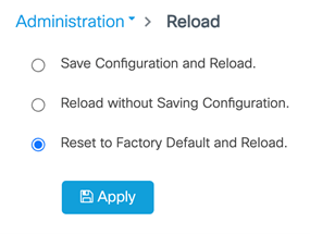
Please do not use this feature in lieu of doing a write erase from the CLI or from the Administration page, Reload option of the WebUI. Invoke the reload with the Reset to Factory Default and Reload option and click Apply. See the following figure.

If service declassify erase-all is invoked, after restoring the IOS-XE image and device configuration, you must re-license the device using the standard Cisco Smart Licensing procedures which ultimately require a Cisco Smart Account and access to the internet or a satellite license server.