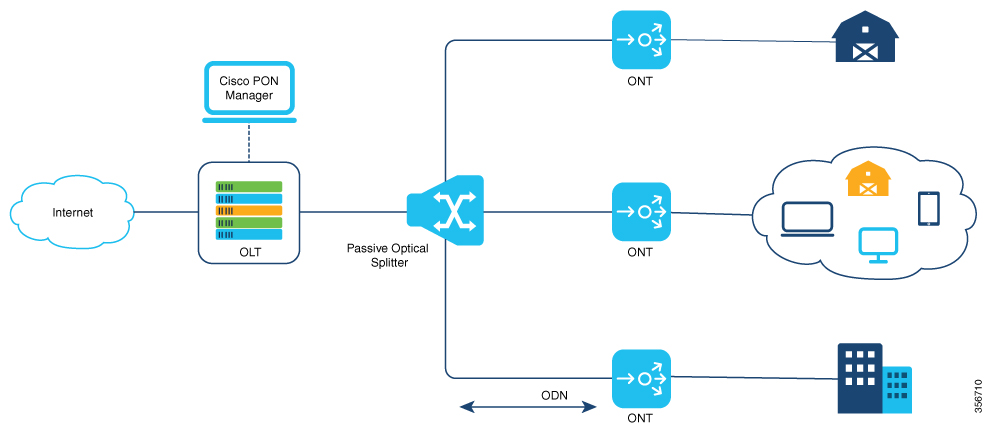
Cisco Catalyst PON Series OLT Overview
The Cisco Catalyst PON Series OLT is an aggregation device that is located at a service provider's central office of the PON network. The main functions of a Cisco Catalyst PON Series OLT are traffic scheduling, buffer control, and bandwidth allocation. The Cisco Catalyst PON Series OLT manages the network traffic that is in the form of video, data, and voice signals in a PON network, and sends them downstream to the Cisco Catalyst PON Series ONTs on the network. The Cisco Catalyst PON Series OLT also receives the signals from the Cisco Catalyst PON Series ONTs located at an end user's premises and sends them to their destination over the internet.
A Cisco Catalyst PON Series OLT can support up to 128 Cisco Catalyst PON Series ONTs per port. A Cisco Catalyst PON Series OLT provides 8/16xPON ports, 4xG combo ports and 2x10G small form-factor pluggable (SFP+) ports for uplink. A Cisco Catalyst PON Series OLT carries abundant services and flexible network mode over one optical network, and is especially suitable for networks such as enterprise LAN, video application, and high-speed internet.
Cisco Catalyst PON Series OLT Models
The following table lists the Cisco Catalyst PON Series OLT models and their description.
|
Model |
Description |
|---|---|
|
CGP-OLT-8T |
Cisco Catalyst PON Series OLT with 8xPON port, 4x1 G combo port, and 2x10 G SFP+ module uplink slot. |
|
CGP-OLT-16T |
Cisco Catalyst PON Series OLT with 16xPON port, 4x1 G combo port, and 2x10 G SFP+ module uplink slot. |
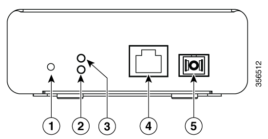
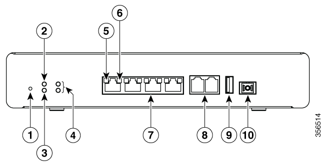
Front Panel
This section describes the front-panel components of Cisco Catalyst PON Series OLT.
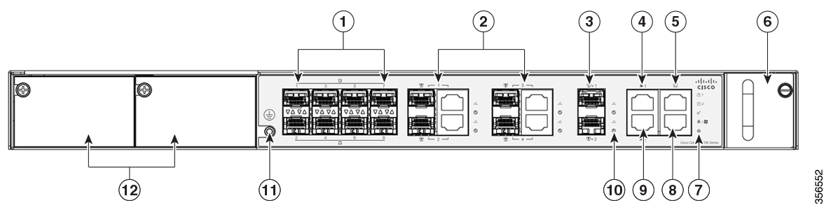
|
1 |
PON ports |
7 |
System LEDs |
|
2 |
1 G combo ports |
8 |
Auxiliary port |
|
3 |
10 G SFP+ ports |
9 |
Reserve alarm port |
|
4 |
Reserve alarm port |
10 |
Port LEDs |
|
5 |
Console port |
11 |
Grounding connector |
|
6 |
Fan module |
12 |
Power modules |
|
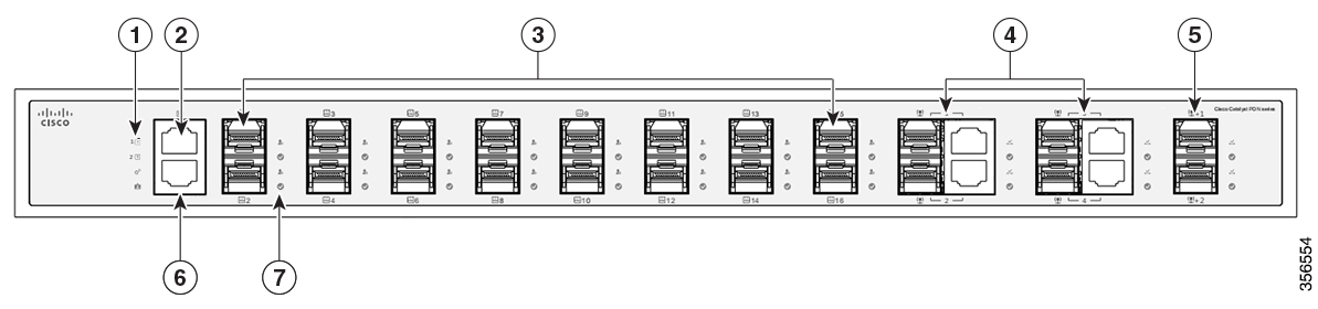
1 |
System LEDs |
5 |
10 G SFP+ port |
|
2 |
Console port |
6 |
Auxiliary port |
|
3 |
PON ports |
7 |
Port LEDs |
|
4 |
1 G combo ports |
- |
- |
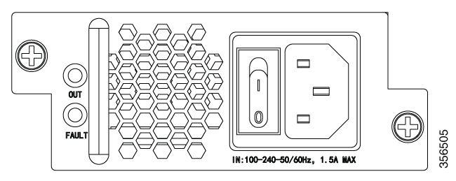
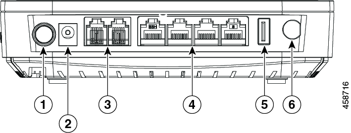
Rear Panel
This section describes the rear-panel components of CGP-OLT-16T:

|
1 |
AC or DC power connector |
2 |
Grounding connector |
Ports
PON Ports
The PON ports use multi-source agreement (MSA) type UPC or SC-PC fiber connector. The PON ports support a bandwidth of 2.466 Gbps downstream and 1.244 Gbps upstream.
Console Port
The console port connects the Cisco Catalyst PON Series OLT to a PC running Microsoft Windows or to a terminal server and uses the RJ-45 crossover cable. The RJ-45 console port connection uses the supplied RJ-45-to-DB-9 female cable.
Auxiliary Port
The auxiliary port connects the Cisco Catalyst PON Series OLT to a host such as a Windows workstation or a terminal server through the auxiliary port. The auxiliary out-of-band management port is a virtual routing and forwarding (VRF) interface and uses an RJ-45 crossover cable.
1 G Combo Ports
A combo port is a combination of an SFP interface and an RJ-45 port. When the SFP interface is active, the adjacent RJ-45 port is disabled. The 1 G ports use LC connectors for fiber-optic connections and RJ-45 connectors for copper connections.
10 G SFP+ Ports
The 10 G ports use LC connector cables for fiber-optic connections and RJ-45 connector cables for copper connections. The SFP slots support only SFP+ modules. These SFP+ modules are field replaceable, and provide uplink interfaces when installed in an SFP+ module slot.
For more information on compatible Cisco SFP+ modules, see the Cisco Catalyst PON Series Switches Release Notes.
Reserve Alarm Port
The reserve alarm port connects to external monitoring systems such as the Environment Monitor System.
 Note |
This functionality is currently disabled. |
Power Supply
The Cisco Catalyst PON Series OLT chassis has redundant power supply slots that operate with one or two power supply modules. The chassis supports field-replaceable AC-input and DC-input power supply modules.
Note |
Hybrid power supply plugs are not supported. |
AC Power Supply
The following table lists the power supply ratings.
| Input Voltage (VAC) | Output Power (Watts) |
|---|---|
|
220 |
100 |
|
110 |
100 |
DC Power Supply

The following table lists the power supply ratings.
| Input Voltage (VAC) | Output Power (Watts) |
|---|---|
|
-36 to -72VDC (with extended range upto -75VDC) Voltage differential between inputs is unlimited. |
100 |
LEDs
You can use LEDs to monitor the activity and performance of Cisco Catalyst PON Series OLT.
|
LED |
Color |
Indication |
|---|---|---|
|
PWR1 and PWR2 |
Green (solid) |
Normal power from power supply |
|
OFF |
No power from power supply |
|
|
RUN |
Green (blinking) |
OLT is running normally |
|
OFF or Green (solid) |
OLT is not running or OLT is running abnormally |
|
|
AUX |
OFF |
Auxiliary port is not connected |
|
Green (solid) |
Auxiliary port is connected, but not transmitting data |
|
|
Green (blinking) |
Auxiliary port is connected and is transmitting data |
|
|
OUT |
Green (solid) |
Power supply is normal |
|
OFF |
No power supply |
|
|
FAULT |
Red (Solid) |
Power supply is abnormal |
|
OFF |
Power supply is normal |
|
LED |
Color |
Indication |
|---|---|---|
|
PON port |
||
|
REG |
Green (solid) |
ONT is registered on the OLT. |
|
OFF |
No ONT is registered on the OLT. |
|
|
ACT |
Green (blinking) |
OLT is receiving and transmitting data |
|
OFF |
OLT is not receiving and transmitting data |
|
|
1 G port and 10 G port |
||
|
LINK |
Green (solid) |
Connection is established |
|
OFF |
No connection |
|
|
ACT |
Green (blinking) |
OLT is receiving and transmitting data |
|
OFF |
OLT is not receiving and transmitting data |
|

 Feedback