- Configure Fabric Edge
- Adding an Extended Node to Cisco SD-Access Network
- Adding a Policy Extended Node to Cisco SD-Access Network
- Migrating an Extended Node to a Policy Extended Node
- Provisioning Wireless Access Points
- Endpoint Onboarding
- Provisioning a Software Image
- Template Provisioning
- Provisioning a Template on a Device
Extended Enterprise for SD-Access Deployments Implementation Guide
This Extended Enterprise for SD-Access Deployments Implementation Guide describes the implementation of the design defined in the Extended Enterprise SD-Access Design Guide. This guide incorporates a broad set of technologies, features, and applications for helping customers extend the enterprise Information Technology (IT) services to outdoor spaces.
Cisco Validated Designs (CVDs) provide the foundation for systems design and are based on common use cases or engineering system priorities. Each guide details the methodology for building solutions, and more importantly, the recommendations have been comprehensively tested by Cisco engineers to help ensure a faster, more reliable, and predictable deployment.
Extended Enterprise CVD
An enterprise has production, storage, distribution, and outdoor facilities. IT reach extends beyond the traditional carpeted space to non-carpeted spaces as well. IT can now extend network connectivity, security policy, and management to the outside, warehouses, and distribution centers with the same network operating systems and network management that offer automation, policy enforcement, and assurance. The Cisco Digital Network Architecture (Cisco DNA) is an architecture based on automation and analytics that provides comprehensive network visibility and end-to-end policy delivery at scale. Cisco DNA enables customers to capture business intent and activate it network wide in the campus and in non-carpeted spaces where the operations happen.
This CVD outlines the steps for both IT and operations teams to accomplish business goals by digitizing the operations in the outdoor spaces of an enterprise. It includes guidance for implementing Extended Enterprise use cases with the customer's existing Cisco DNA Center.
For More Information
To learn more about Extended Enterprise solutions, please visit:
Scope and Audience for this Document
This implementation document provides deployment guidance for an Extended Enterprise network design. It is a companion to the associated design and deployment guides for enterprise networks, which provide guidance in how to deploy the most common implementations of SD-Access. This guide discusses the extended enterprise implementation for SD-Access deployments.
This CVD discusses the Extended Enterprise implementation for Cisco Software-Defined Access (SD-Access) deployments. For the associated deployment guides, design guides, and white papers, refer to the following documents:
■![]() Cisco Enterprise Networking design guides:
Cisco Enterprise Networking design guides:
–![]() https://www.cisco.com/go/designzone
https://www.cisco.com/go/designzone
■![]() Cisco IoT Solutions design guides:
Cisco IoT Solutions design guides:
–![]() https://www.cisco.com/go/iotcvd
https://www.cisco.com/go/iotcvd
■![]() Cisco Extended Enterprise Solutions Overview:
Cisco Extended Enterprise Solutions Overview:
–![]() https://www.cisco.com/go/extendedenterprise
https://www.cisco.com/go/extendedenterprise
■![]() Extended Enterprise Design Guide for non-fabric and SD-Access:
Extended Enterprise Design Guide for non-fabric and SD-Access:
–![]() https://www.cisco.com/c/en/us/td/docs/solutions/Verticals/EE/DG/ee-dg.html
https://www.cisco.com/c/en/us/td/docs/solutions/Verticals/EE/DG/ee-dg.html
What is in this Guide?
This document is organized in the following sections:
|
|
|
|---|---|
Check list with required SD-Access setup and configurations for Extended Enterprise fabric deployment |
|
Details Cisco DNA Center design options relevant to Extended Enterprise implementation for Cisco SD-Access deployments. |
|
Creating Segmentation with Cisco DNA Center Policy Application |
Explains segmentation options, how to add security policies and necessary configurations to provide micro segmentation. |
Provides guidance to add Industrial Ethernet (IE) switches as extended nodes or policy extended nodes to the fabric, it also covers how to add access points (APs) and endpoints to the industrial switches. |
|
Gives an overview of Cisco DNA Center assurance capabilities for Extended Enterprise deployments. |
This guide assumes that the user has already installed Cisco DNA Center, Cisco Identity Services Engine (ISE), and Wireless LAN Controller (WLC) in the enterprise network. For further information, refer to the CVD Software-Defined Access & Cisco DNA Center Management Infrastructure for implementation details:
Implementation Overview
The SD-Access for an Extended Enterprise deployment is based on the Cisco Software-Defined Access Design Guide: https://cs.co/sda-sdg. The design enables wired and wireless communications between devices in an outdoor or group of outdoor environments, as well as interconnection to the WAN and Internet edge at the network core.
References
■![]() CVD Software-Defined Access Medium and Large Site Fabric Provisioning at the following URL:
CVD Software-Defined Access Medium and Large Site Fabric Provisioning at the following URL:
–![]() https://cs.co/sda-fabric-pdg
https://cs.co/sda-fabric-pdg
■![]() CVD Software-Defined Access for Distributed Campus at the following URL:
CVD Software-Defined Access for Distributed Campus at the following URL:
–![]() - https://cs.co/sda-distrib-pdg
- https://cs.co/sda-distrib-pdg
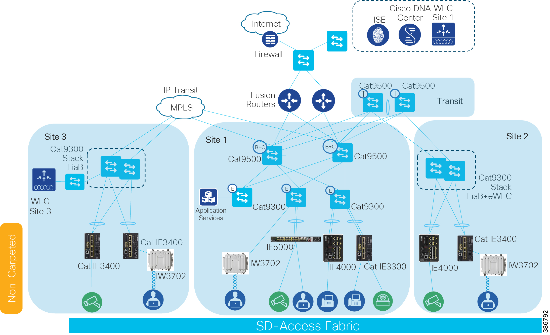
This document provides implementation guidelines for a multi-site SD-Access deployment. The validation topology showcases an example of a deployment with three sites as described below.
Site 1 is the largest site in the deployment and is connected directly to the fusion devices by IP transit links. Its node roles are divided so that the Cisco Catalyst 9500s act as the combined fabric border and control nodes, and Cisco Catalyst 9300s in stacking configuration serve as the fabric edge nodes. Sites 2 and 3 are smaller deployments and have a stacked Catalyst 9300 serving as fabric border, control, and edge nodes, known as Fabric-in-a-Box (FiaB). Both Sites 2 and 3 connect back to the Catalyst 9500s in Site 1 which provides access to the Internet and to shared services. Site 1 has the WLC located on the shared services block in this implementation.
Site 2 is connected to Site 1 by SD-Access Transit with Catalyst 9500s serving as transit control plane nodes. This preserves fabric connectivity between the two sites and allows Scalable Group Tag (SGT) and virtual network information to be carried inline in the VXLAN header. The Site 2 WLC is embedded on the FiaB node (eWLC). Note that each fabric site requires a dedicated WLC when using SDA wireless.
For latency requirements from Cisco DNA Center to a fabric edge, refer to the Cisco DNA Center User Guide at the following URL:
https://www.cisco.com/c/en/us/support/cloud-systems-management/dna-center/products-user-guide-list.html
For network latency requirements from the AP to the WLC, refer to the latest Campus LAN and Wireless LAN Design Guide at Cisco Design Zone:
https://www.cisco.com/c/en/us/solutions/design-zone/networking-design-guides/campus-wired-wireless.html#~campus-guides
Site 3 is connected by IP transit over Multiprotocol Label Switching (MPLS) infrastructure so communication between the two fabric sites must exit the fabric at the border node and re-enter the fabric at the border node of the adjacent site. This does not allow virtual networks or SGTs to be carried inline and requires virtual routing and forwarding (VRF) and SGT Exchange Protocol (SXP) to maintain network segmentation. VRFs will maintain virtual network isolation while SXP will transmit IP-to-SGT mappings to each border node to re-tag traffic with the appropriate source tag upon re-entry to the Fabric. Site 3 has a dedicated WLC as required when using SD-Access wireless. To meet latency requirements, a non-fabric switch is connected to the border of Site 3 to allow IP connectivity with the fabric WLC.For more information on segmentation refer to the Extended Enterprise Design Guide: for non-fabric and SD-Access at the following URL:
https://www.cisco.com/c/en/us/td/docs/solutions/Verticals/EE/DG/ee-dg.html
Each site, building, floor, or geographic location has an enterprise access switch (for example, the Cisco Catalyst 9300) with at least two switches arranged in a stack. Ruggedized Cisco Industrial Ethernet (IE) switches are connected to the enterprise fabric edges as extended nodes or policy extended nodes and thus extend the enterprise network to the non-carpeted spaces.
Figure 1 shows the validation topology.
Security policies are uniformly applied, which provides consistent treatment for a given service across the enterprise and Extended Enterprise networks. Controlled access is given to shared services and other internal networks by appropriate authorization profile assignments.
Application policies are applied to extended nodes using template functionality on Cisco DNA Center.
Validated Hardware/Software Matrix
Table 1 contains a list of the verified hardware and software components.
■![]() Devices that support extended nodes and policy extended nodes are Cisco Catalyst 9300, Cisco Catalyst 9400, and Cisco Catalyst 9500 series switches when configured as fabric edge.
Devices that support extended nodes and policy extended nodes are Cisco Catalyst 9300, Cisco Catalyst 9400, and Cisco Catalyst 9500 series switches when configured as fabric edge.
■![]() Cisco Catalyst 9200 series switches do not support extended nodes.
Cisco Catalyst 9200 series switches do not support extended nodes.
Implementation Prerequisites
This document is a companion of the CVDs: Software-Defined Access & Cisco DNA Center Management Infrastructure, Software-Defined Access Medium and Large Site Fabric Provisioning, and Software-Defined Access for Distributed Campus. This document assumes the user is already familiar with the prescribed implementation and the following tasks are completed:
1.![]() Cisco DNA Center installation
Cisco DNA Center installation
3.![]() Integration of ISE with Cisco DNA Center
Integration of ISE with Cisco DNA Center
4.![]() Discovery and provision of network infrastructure
Discovery and provision of network infrastructure
6.![]() Fabric domain role provision for border, control, and edge nodes
Fabric domain role provision for border, control, and edge nodes
7.![]() WLC installation per fabric site
WLC installation per fabric site
8.![]() Configuration of fabric Service Set Identifier (SSID) and wireless profiles
Configuration of fabric Service Set Identifier (SSID) and wireless profiles
9.![]() Provisioning WLC with SSIDs and addition to the fabric
Provisioning WLC with SSIDs and addition to the fabric
Tip : When implementing SD-Access wireless, one WLC is required per fabric site.
For further information, refer to the following documents for implementation details:
CVD Software-Defined Access & Cisco DNA Center Management Infrastructure
CVD Software-Defined Access Medium and Large Site Fabric Provisioning
CVD Software-Defined Access for Distributed Campus
Design
The Cisco DNA Center design area is used to create the structure and framework of your network within the Cisco DNA Center, including the physical topology, network settings, and device type profiles that you can apply to devices. As part of this design, you can design network hierarchy and settings, configure global wireless settings, create SSIDs, and manage the image repository. Most of these activities are completed as part of the Software-Defined Access Medium and Large Site Fabric Provisioning; however, additional specifications relevant to Extended Enterprise are explained here.
Create IP Address Pools
The Cisco DNA Center IP Address Management (IPAM) tool is used to create and reserve IP address pools for LAN and border automation, Enterprise Network Compute Systems (ENCS)/Network Functions Virtualization (NFV) workflows, and the binding of the subnet segment to a Virtual Network (VN) in host onboarding. IP address pools are defined at the global level and then reserved at the area, building, or floor level. Reserving an IP address pool holds the block of addresses, making them unavailable for use in other areas within Cisco DNA Center. For details on IP address pool creation, refer to the CVD Software-Defined Access Medium and Large Site Fabric Provisioning.
Table 2 -4 shows an example of IP addresses created and reserved on the fabric side on an Extended Enterprise deployment. The example showcases IP address pools for extended nodes, policy extended nodes, access points, and endpoints per fabric site. The example does not show network automation IP address pools.
Table 3 IP Pools Used in Site 2 (SD-Access Transit)
Table 4 IP Pools Used in Site 3 (IP Transit)
Design Considerations
In the overlay, IP subnets can be stretched across the fabric without flooding issues that can happen on large Layer 2 networks. Use fewer subnets and DHCP scopes for simpler IP addressing and DHCP scope management. Subnets are sized according to the services that they support, versus being constrained by the location of a gateway. Enabling the optional broadcast flooding (Layer 2 flooding) feature can limit the subnet size based on the additional bandwidth and endpoint processing requirements for the traffic mix within a specific deployment.
Different overlay networks can support overlapping address space, but be aware that most deployments require shared services across all VNs and some may use inter-VN communication. Avoid overlapping address space so that the additional operational complexity of adding a network address translation (NAT) device is not required for shared services communication.
Managing the Image Repository
The Cisco DNA Center stores all the unique software images according to image type and version. You can view, import, and delete software images.
Viewing Software Images
1.![]() From the Cisco DNA Center dashboard, choose Design > Image Repository.
From the Cisco DNA Center dashboard, choose Design > Image Repository.
Software images are displayed by device type. Virtual devices are not displayed by default.
2.![]() Toggle the Virtual tab to view images for virtual devices.
Toggle the Virtual tab to view images for virtual devices.
As devices are discovered or manually added to the Cisco DNA Center, information about their software image is added to the image repository. During discovery:
–![]() If an image for a device does not appear under its family, the Cisco DNA Center will add an entry for that image under the correct platform.
If an image for a device does not appear under its family, the Cisco DNA Center will add an entry for that image under the correct platform.
–![]() If the image is already listed for that device family, the Using Image column will be incremented for the appropriate family.
If the image is already listed for that device family, the Using Image column will be incremented for the appropriate family.
Uploading an Image
1.![]() From the Cisco DNA Center dashboard, choose Design > Image Repository.
From the Cisco DNA Center dashboard, choose Design > Image Repository.
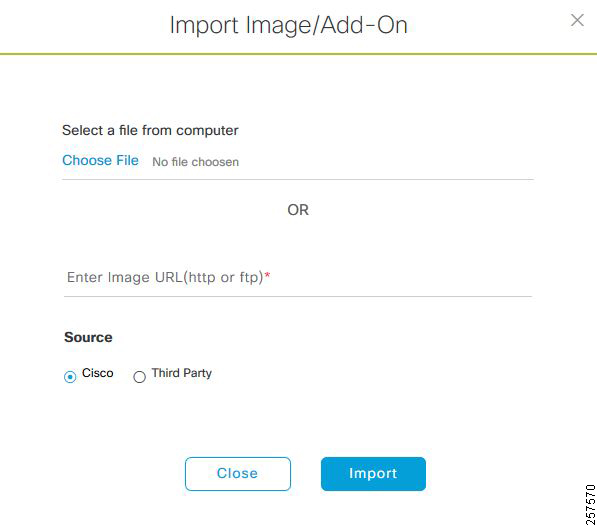
3.![]() In the pop-up window, click Choose File to navigate to a software image stored locally on your PC or specify an HTTP or FTP source where the image resides. For Cisco software images, ensure that the Cisco radio button beneath Source is selected. When finished, click Import.
In the pop-up window, click Choose File to navigate to a software image stored locally on your PC or specify an HTTP or FTP source where the image resides. For Cisco software images, ensure that the Cisco radio button beneath Source is selected. When finished, click Import.
4.![]() Verify that the image was imported correctly. After successful import of an image, a notification is displayed at the bottom right of the screen. If an image is not imported directly from Cisco.com, the user will need to navigate to the Imported Images group and click the drop-down arrow to display all imported images. If the trash can icon to the far right of an image is blue, the image has been imported to Cisco DNA Center. If the trash can icon is gray and not selectable, the image has not been imported to Cisco DNA Center.
Verify that the image was imported correctly. After successful import of an image, a notification is displayed at the bottom right of the screen. If an image is not imported directly from Cisco.com, the user will need to navigate to the Imported Images group and click the drop-down arrow to display all imported images. If the trash can icon to the far right of an image is blue, the image has been imported to Cisco DNA Center. If the trash can icon is gray and not selectable, the image has not been imported to Cisco DNA Center.
Tip: If the image you just imported is not present in the list of imported images, click Refresh next to the Filter icon. The total number of images will increment by one and the image will be displayed in the list of imported images.
5.![]() Assign the appropriate image to a platform by clicking Assign next to the image. A pop-up window will appear, on which the user can select device platforms for the image. When finished selecting platforms, click Assign.
Assign the appropriate image to a platform by clicking Assign next to the image. A pop-up window will appear, on which the user can select device platforms for the image. When finished selecting platforms, click Assign.
Creating Segmentation with Cisco DNA Center Policy Application
This chapter will guide you through configurations needed on Cisco DNA Center and ISE to provide network segmentation and intent-based security policies as presented in the Extended Enterprise Design Guide for non-fabric and SD-Access.
SD-Access supports two levels of segmentation: macro and micro. Macro-segmentation uses overlay networks with VRF instances. Micro-segmentation uses scalable group tags (SGTs) to apply policy to groups of users or devices. Segmentation using SGTs allows for simple-to-manage, group-based policies and enables granular data plane isolation between groups of endpoints within a virtualized network. Using SGTs also enables scalable deployment of policy without having to do cumbersome updates for these policies based on IP addresses.
Use virtual networks (macro-segmentation) when requirements dictate isolation at both the data plane and control plane. In general, if devices need to communicate with each other, they should be placed in the same virtual network. If communication is required between different virtual networks, use an external firewall or other device to enable inter-VN communication. A Virtual Network provides the same behavior and isolation as VRFs.
In the parking lot example provided in the Extended Enterprise Design Guide for non-fabric and SD-Access, two separate networks need to be completely isolated. One network provides employees access to the network and resources, and a separate network connects things such as security cameras, badge readers, and parking sensors. Those two networks are independent of each other and communication is never required between the two.
In this case, macro-segmentation is used to create two separate VNs: EMPLOYEE_VN and BUILDING_VN. Continuing with the example, IP cameras and security contractors may exist on the BUILDING_VN. Contractors should be able to access the cameras remotely for troubleshooting, but IP cameras should not be able to reach other IP cameras to protect the network from unauthorized access. In that scenario, we can apply a micro-segmentation policy using the policy application in the Cisco DNA Center, which leverages APIs to program the ISE TrustSec matrix.
The Cisco DNA Center policy application supports creating and managing VNs, policy administration and contracts, and SGT creation. The zero trust model and unified policy is at the heart of and the differentiator in the SD-Access solution. Therefore, deployments should set up their SD-Access policy (VNs and contracts) before doing any SD-Access provisioning.
In this chapter, the segmentation for the overlay network is defined. (Note that the overlay network will only be fully created until the host onboarding stage). This process virtualizes the overlay network into multiple self-contained virtual networks. After VN creation, the TrustSec policies are created to define which endpoints and groups within a VN can communicate.
Add an Enterprise Overlay Virtual Network for Macro Segmentation
VNs are created first and then group-based access control policies are used to enforce policy within the VN:
1.![]() From the Cisco DNA Center dashboard, navigate to POLICY > Virtual Network.
From the Cisco DNA Center dashboard, navigate to POLICY > Virtual Network.
2.![]() Click the + to create a new virtual network.
Click the + to create a new virtual network.
3.![]() Enter a virtual network name (example: BUILDING).
Enter a virtual network name (example: BUILDING).
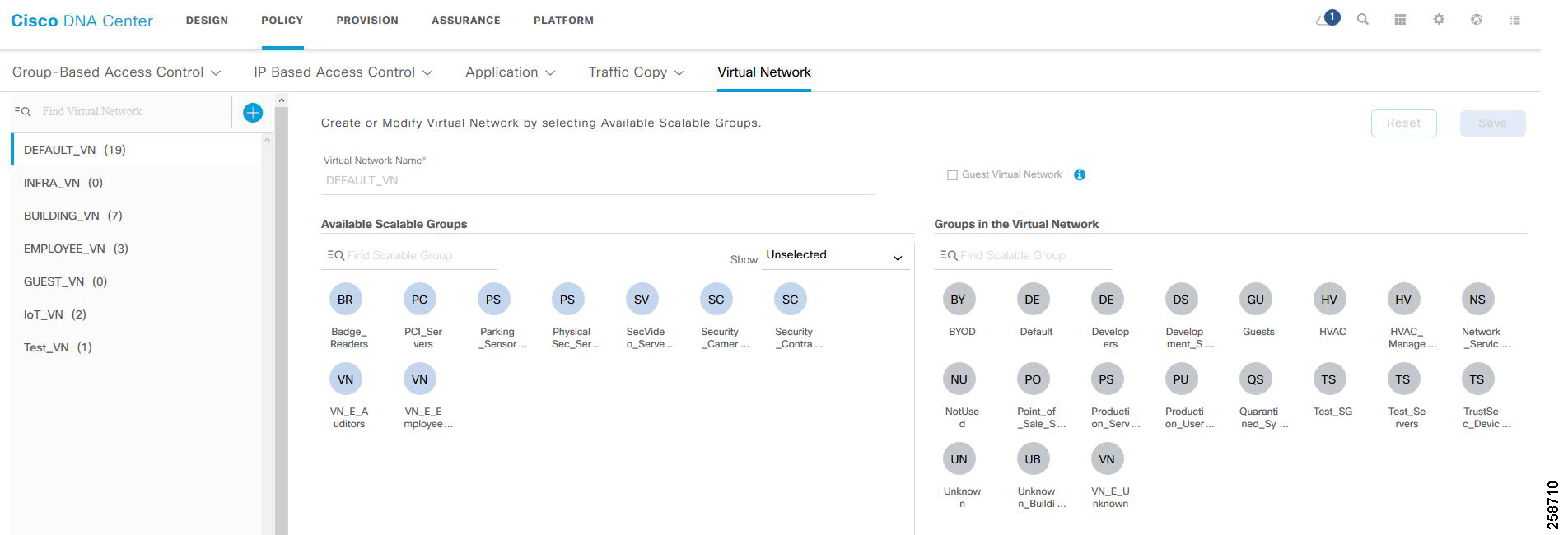
4.![]() Drag scalable groups from the Available Scalable Groups pane into the Groups in the Virtual Network pane. This step needs to be revisited later after all needed scalable groups are created.
Drag scalable groups from the Available Scalable Groups pane into the Groups in the Virtual Network pane. This step needs to be revisited later after all needed scalable groups are created.
6.![]() Verify that the VN with associated groups is defined and appears in the list on the left. These virtual network definitions are now available for provisioning the fabric in later steps.
Verify that the VN with associated groups is defined and appears in the list on the left. These virtual network definitions are now available for provisioning the fabric in later steps.
7.![]() Repeat this procedure for each overlay network.
Repeat this procedure for each overlay network.
Tip: A common configuration convention is to use all caps for any user-defined elements. The VNs defined in the policy application are provisioned to the devices as a VRF definition. Using all caps to identify these user-defined variables can assist in troubleshooting and monitoring. This convention is a best practice recommendation.
Figure 3 Create a Virtual Network
Intent-Based Security Policy
Intent-based security gives the administrator the ability to express operational intent and automatically have the system select the appropriate IT-defined security policies without requiring network or security skills.
As part of the design decisions in advance of your network deployment, you decide network segmentation strategies for the organization. Micro-segmentation uses SGTs to apply policy to groups of users or device profiles. The desired outcomes of policy application using segmentation may be easily accommodated with group policies. In Cisco DNA Center, this is done by using group-based access control policies.
Group-Based Access Control Components
The Cisco SD-Access solution supports creation and provisioning of the following policy constructs:
■![]() Scalable groups—Cisco TrustSec uses tags to represent logical group privilege. SGTs are used in access policies to control traffic flowing through switches, routers, and firewalls.
Scalable groups—Cisco TrustSec uses tags to represent logical group privilege. SGTs are used in access policies to control traffic flowing through switches, routers, and firewalls.
■![]() Security Group Access Control List (SGACL)—An administrator uses policy enforcement to control the operations performed by the user based on the security group assignments and destination resources. Cisco DNA Center refers to these as “Group-Based Access Control policies” to express the intent of these constructs.
Security Group Access Control List (SGACL)—An administrator uses policy enforcement to control the operations performed by the user based on the security group assignments and destination resources. Cisco DNA Center refers to these as “Group-Based Access Control policies” to express the intent of these constructs.
■![]() Access Contract—An administrator uses policy enforcement to control the operations performed by the user based on destination port and protocol information. Cisco DNA Center has two predefined access contracts—permit and deny—which allow all traffic or deny all traffic between the selected groups, respectively.
Access Contract—An administrator uses policy enforcement to control the operations performed by the user based on destination port and protocol information. Cisco DNA Center has two predefined access contracts—permit and deny—which allow all traffic or deny all traffic between the selected groups, respectively.
Tip : Starting at Cisco DNA Center version 1.3.1, use of the Policy > Group-Based Access Control tab requires migration of policy information from ISE to Cisco DNA Center. Afterwards, Cisco DNA Center is considered the main policy information management point for TrustSec policy, and TrustSec information within ISE becomes read-only. After policy sync all changes should be made through Cisco DNA Center. Until policy migration is complete, the Policy > Group-Based Access Control tab is not available for use and TrustSec policy is managed through ISE.
For more information on synchronization of policy information between Cisco DNA Center and ISE, refer to the Cisco DNA Center User Guide at the following URL: https://www.cisco.com/c/en/us/support/cloud-systems-management/dna-center/products-user-guide-list.html
Creating Security Group Tags
1.![]() Navigate to POLICY > Group-Based Access Control > Scalable Groups.
Navigate to POLICY > Group-Based Access Control > Scalable Groups.
2.![]() Click Create Scalable Group.
Click Create Scalable Group.
3.![]() In the Create Scalable Group pane, enter a name and description (optional) for the scalable group.
In the Create Scalable Group pane, enter a name and description (optional) for the scalable group.
The following characters are supported for the Name field:
The scalable group name must start with an alphabetic character.
4.![]() (Optional) If necessary, specify a Tag Value (Cisco DNA Center will generate a default value if not specified). The valid range for Tag Value is from 2 to 65519 and must not be in use by another scalable group.
(Optional) If necessary, specify a Tag Value (Cisco DNA Center will generate a default value if not specified). The valid range for Tag Value is from 2 to 65519 and must not be in use by another scalable group.
5.![]() Choose Virtual Networks for the tag.
Choose Virtual Networks for the tag.
6.![]() From the Virtual Networks drop-down list choose the VNs to be associated with this scalable group. By default, the default virtual network (DEFAULT_VN) is chosen.
From the Virtual Networks drop-down list choose the VNs to be associated with this scalable group. By default, the default virtual network (DEFAULT_VN) is chosen.
7.![]() (Optional) Check the Propagate to ACI check box if you want the scalable group to be propagated to Cisco Application Centric Infrastructure (ACI).
(Optional) Check the Propagate to ACI check box if you want the scalable group to be propagated to Cisco Application Centric Infrastructure (ACI).
Cisco DNA Center communicates to ISE through representational state transfer (REST) API calls; therefore, the newly created security tags are available to use in Cisco DNA Center when configuring policies. Click the Scalable Group Name link to view the details of a scalable group. Click Edit in the View Scalable Group window to update the scalable group details. When you click Deploy, Cisco DNA Center requests Cisco ISE to send notifications about the changes to the network devices. You can check the deployment status in the Deploy column.
Create a Micro-Segmentation Policy using SGTs
Micro-segmentation creates network segmentation that relies on the use of role- or group-based membership, regardless of IP addressing, in order to create policies that allow segmentation in the network.
Micro-segmentation policies are customized for an organization deployment. The following example shows a basic policy that can be used to deny IP cameras communication with other IP cameras.
Deployment considerations
■![]() The TrustSec matrix uses an allowed list model by default; if a policy is not created traffic will be allowed. Change to a blocked list model has to be done with extreme caution. This model requires a detailed study of the control plane traffic as well as it has the potential to block ALL traffic, the moment it is enabled.
The TrustSec matrix uses an allowed list model by default; if a policy is not created traffic will be allowed. Change to a blocked list model has to be done with extreme caution. This model requires a detailed study of the control plane traffic as well as it has the potential to block ALL traffic, the moment it is enabled.
■![]() Policy implementation is optimized by devices dynamically downloading SGACL policies only applicable to the assets they protect. When using the default allowed list model, explicit allow policies are redundant. Avoid configuring redundant policies to further optimize the number of policies downloaded to devices.
Policy implementation is optimized by devices dynamically downloading SGACL policies only applicable to the assets they protect. When using the default allowed list model, explicit allow policies are redundant. Avoid configuring redundant policies to further optimize the number of policies downloaded to devices.
Create a Policy
1.![]() Navigate to POLICY > Group-Based Access Control > Policies. Click Create Policies.
Navigate to POLICY > Group-Based Access Control > Policies. Click Create Policies.
2.![]() Click Source to Destination(s) to create an access control policy with a single source and multiple destination groups.
Click Source to Destination(s) to create an access control policy with a single source and multiple destination groups.
a.![]() Click the radio button next to the source scalable group that you want to select. If the scalable group that you need does not exist, click the Create Scalable Group button to create a new scalable group.
Click the radio button next to the source scalable group that you want to select. If the scalable group that you need does not exist, click the Create Scalable Group button to create a new scalable group.
c.![]() Choose the destination scalable groups to which the selected source scalable group must be mapped. If necessary, you can view the scalable group details and edit the scalable groups. An orange triangle icon is displayed near a scalable group if a policy already exists between the source and destination.
Choose the destination scalable groups to which the selected source scalable group must be mapped. If necessary, you can view the scalable group details and edit the scalable groups. An orange triangle icon is displayed near a scalable group if a policy already exists between the source and destination.
e.![]() Click the radio button next to the contract that you want to select. If necessary you can view and edit the contract details.If the contract that you need does not exist, click the Create Contract button to create a new contract. A contract defines a set of rules that allow or deny traffic based on protocols or ports.
Click the radio button next to the contract that you want to select. If necessary you can view and edit the contract details.If the contract that you need does not exist, click the Create Contract button to create a new contract. A contract defines a set of rules that allow or deny traffic based on protocols or ports.
Tip : You can only choose one contract for a policy.
f.![]() Click Next. The Summary window lists the policies that are created based on the chosen scalable groups and contract.
Click Next. The Summary window lists the policies that are created based on the chosen scalable groups and contract.
h.![]() Click Deploy to send notifications about the changes to the network devices.
Click Deploy to send notifications about the changes to the network devices.
3.![]() Click Destination to Source(s) to create an access control policy with a single destination and multiple source groups.
Click Destination to Source(s) to create an access control policy with a single destination and multiple source groups.
a.![]() Click the radio button next to the destination scalable group that you want to select. If the scalable group that you need does not exist, click Create Scalable Group to create a new scalable group.
Click the radio button next to the destination scalable group that you want to select. If the scalable group that you need does not exist, click Create Scalable Group to create a new scalable group.
c.![]() Choose the source scalable groups to which the selected destination scalable group must be mapped. If necessary, you can view the scalable group details and edit the scalable groups. An orange triangle icon is displayed near a scalable group if a policy already exists between the source and destination.
Choose the source scalable groups to which the selected destination scalable group must be mapped. If necessary, you can view the scalable group details and edit the scalable groups. An orange triangle icon is displayed near a scalable group if a policy already exists between the source and destination.
e.![]() Click the radio button next to the contract that you want to select. If necessary you can view and edit the contract details. If the contract that you need does not exist, click Create Contract to create a new contract. A contract defines a set of rules that allow or deny traffic based on protocols or ports.
Click the radio button next to the contract that you want to select. If necessary you can view and edit the contract details. If the contract that you need does not exist, click Create Contract to create a new contract. A contract defines a set of rules that allow or deny traffic based on protocols or ports.
Tip : You can choose only one contract for a policy.
f.![]() Click the Next button. The Summary window lists the policies that are created based on the selected scalable groups and contract
Click the Next button. The Summary window lists the policies that are created based on the selected scalable groups and contract
h.![]() Click Deploy to send notifications about the changes to the network devices.
Click Deploy to send notifications about the changes to the network devices.
Tip : You can toggle between the List view and the Drag and Drop view using the Toggle button displayed in the upper right corner of the Scalable Group listing area. The Drag and Drop view allows you to drag and drop the scalable groups to the Source and Destination fields while creating the access control policy. However, only the first 50 scalable groups are listed in the Drag and Drop view. It is recommended to use the List view if you have a larger number of scalable groups (more than 50) to view all the scalable groups.
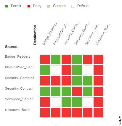
Figure 4 Creating Security Policy
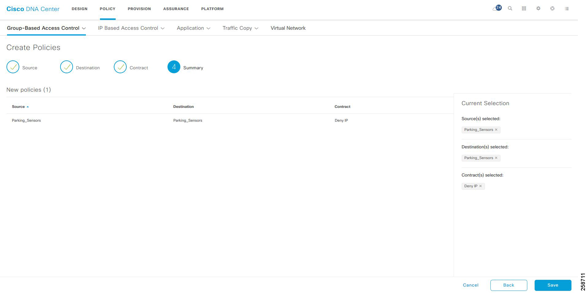
Figure 5 TrustSec Policy Matrix displaying BUILDING VN Tags
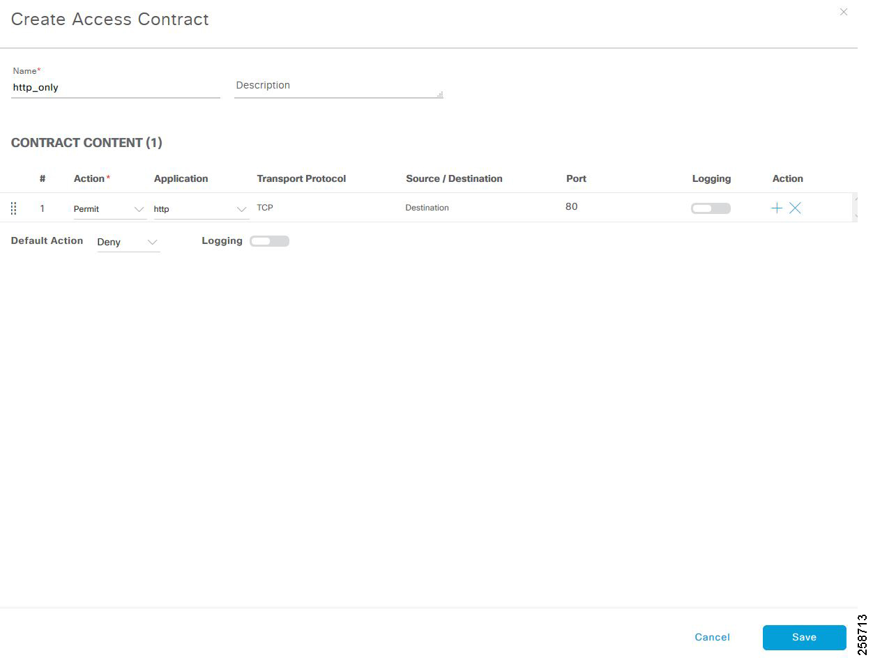
Creating Custom Contracts
The two default options for policy enforcement are permit and deny; however, it is possible to create custom contracts for more granularity. After creating a contract, it can be used in security policies.
1.![]() Navigate to Policy >Group-Based Access Control > Access Contracts.
Navigate to Policy >Group-Based Access Control > Access Contracts.
2.![]() Click Create Access Contract.
Click Create Access Contract.
3.![]() In the Create Access Contract pane, enter a name and description for the contract.
In the Create Access Contract pane, enter a name and description for the contract.
4.![]() Create the traffic filter rules:
Create the traffic filter rules:
- From the Action drop-down list, choose Deny or Permit.
- From the Application drop-down list, choose the application for which you want to apply that action. The port and protocol are automatically selected based on the application that you select. If you want to specify the transport protocol, source port, and destination port, choose the Advanced option in the Application drop-down list.
You can create multiple rules. To create multiple rules to a contract, click the Plus symbol (+) and choose the settings for the Action and Application columns. The rules are checked in the order in which they are listed in the contract. Use the handle icon at the left end of a rule to drag and change the order of the rule.
You can enable or disable logging for any traffic filter rule (including the default action) by clicking the Logging toggle. Logging is disabled by default. When logging is enabled, the network device sends a syslog message when the traffic filter rule is hit. This might be helpful in troubleshooting and initial testing of a policy. However, we recommend that you use this option sparingly because it might have resource and performance impacts on the network devices.
Tip: Logging on contract rules is not supported on policy extended node.
5.![]() From the Default Action drop-down list, choose Deny or Permit. You can enable logging for the default action, if required.
From the Default Action drop-down list, choose Deny or Permit. You can enable logging for the default action, if required.
7.![]() Click Deploy to send notifications about the changes to the network devices.
Click Deploy to send notifications about the changes to the network devices.
Role of Extended Nodes and Policy Extended Nodes on TrustSec
As explained in the Design Guide, TrustSec is defined in three activities: classification, propagation, and enforcement.
802.1x and MAB authentication is enabled on a policy extended node to communicate with Cisco ISE in order to download the VLAN and/or scalable group tag (SGT) attributes for the endpoints. The SGT is applied differently on extended nodes and policy extended nodes.
■![]() For endpoints connected to extended nodes, VLAN-to-SGT mapping is used for classification. When the endpoint is authorized it is moved to the appropriate VLAN configured on ISE authorization policy. An entry for the endpoint is created on the closest fabric edge, linking the IP address to the VLAN SGT as configured on the host onboarding page. For more information on host onboarding configuration refer to Creating Extended Nodes Host Pool. For endpoints connected to policy extended nodes, the SGT is downloaded to the access port.
For endpoints connected to extended nodes, VLAN-to-SGT mapping is used for classification. When the endpoint is authorized it is moved to the appropriate VLAN configured on ISE authorization policy. An entry for the endpoint is created on the closest fabric edge, linking the IP address to the VLAN SGT as configured on the host onboarding page. For more information on host onboarding configuration refer to Creating Extended Nodes Host Pool. For endpoints connected to policy extended nodes, the SGT is downloaded to the access port.
■![]() For endpoints connected to policy extended nodes, the SGT is downloaded to the access port.
For endpoints connected to policy extended nodes, the SGT is downloaded to the access port.
Tip: port-based authentication for extended nodes is available as of Cisco DNA center 1.3.3.0.
■![]() For endpoints connected to extended nodes, the SGT is added to the VXLAN header on the fabric edge. Consequently, the extended node is not aware of the tag and policies cannot be enforced for intra-VLAN traffic.
For endpoints connected to extended nodes, the SGT is added to the VXLAN header on the fabric edge. Consequently, the extended node is not aware of the tag and policies cannot be enforced for intra-VLAN traffic.
■![]() For endpoints connected to policy extended nodes the SGT is propagated via inline tagging.
For endpoints connected to policy extended nodes the SGT is propagated via inline tagging.
Tip: For SDA wireless endpoints, the SGT is carried on the VXLAN packet from the AP, even when connected to a policy extended node.
Traffic may be enforced on the fabric edge or policy extended node.
■![]() Enforcement on the fabric edge: The fabric edge downloads policies applicable to endpoints connected directly or indirectly (via extended node, policy extended nodes, or APs). Fabric edges enforce traffic destined to endpoints on the SGT VLAN. Enforcement is always done at the fabric edge for endpoints connected to extended nodes.
Enforcement on the fabric edge: The fabric edge downloads policies applicable to endpoints connected directly or indirectly (via extended node, policy extended nodes, or APs). Fabric edges enforce traffic destined to endpoints on the SGT VLAN. Enforcement is always done at the fabric edge for endpoints connected to extended nodes.
■![]() Enforcement on the policy extended node: The policy extended node downloads SGACL policies and enforces for endpoints directly connected to the switch. Policy extended node is desirable when intra-VLAN traffic enforcement is needed on the switch.
Enforcement on the policy extended node: The policy extended node downloads SGACL policies and enforces for endpoints directly connected to the switch. Policy extended node is desirable when intra-VLAN traffic enforcement is needed on the switch.
Tip: In deployments with a mix of extended and policy extended nodes, use a unique SGT per VLAN on the ISE authorization policy. Ensure this SGT is consistent with the SGT assigned on the host onboarding page. This practice will guarantee that enforcement is consistent regardless of enforcement point.
Scalable Group Assignment
Scalable groups can be assigned to endpoints dynamically or statically. Dynamic assignment is done by ISE after authenticating and authorizing the endpoint.
Static assignment may be used when port-based authentication is not possible such as when connecting a server using a trunk port. Detailed steps to configure static assignment are explained in Provisioning.
Dynamic assignment can be used after the endpoint authenticates with ISE.
■![]() For endpoints connected to the fabric edge, policy extended node, or fabric APs, the SGT and VLAN is assigned as a result of authorization.
For endpoints connected to the fabric edge, policy extended node, or fabric APs, the SGT and VLAN is assigned as a result of authorization.
■![]() For endpoints connected to extended nodes the VLAN is assigned as a result of authorization. The VLAN can be associated to an SGT in Cisco DNA Center as described in Provisioning section.
For endpoints connected to extended nodes the VLAN is assigned as a result of authorization. The VLAN can be associated to an SGT in Cisco DNA Center as described in Provisioning section.
ISE Configuration to Support Dynamic SGT Assignment
This section details the required configuration to support dynamic SGT assignment.
Authentication Policy
Authentication policies are used to define the protocols used by ISE to communicate with the endpoints and the identity sources to be used for authentication. ISE evaluates the policy conditions and, based on whether the result is true or false, applies the configured result. The authentication methods tested in this CVD are 802.1x and MAC.
Authentication Bypass (MAB). MAB uses the MAC address of a device to determine access privileges, and this method is used to authenticate end devices that do not support any supplicant software in them, such as 802.1X EAP-TLS, EAP-FAST, and so on.
For more information about MAB, refer to the following URL:
■![]() https://www.cisco.com/c/en/us/products/collateral/ios-nx-os-software/identity-based-networking-services/config_guide_c17-663759.html
https://www.cisco.com/c/en/us/products/collateral/ios-nx-os-software/identity-based-networking-services/config_guide_c17-663759.html
The authentication policy used in Cisco ISE for this CVD checks the protocol and the internal identity store for the endpoint MAC address. To configure the authentication policy in ISE, navigate to Policy > Policy Sets > Default and select the arrow on the right to configure the authentication policy.
Note: In this CVD, the default authentication policy set is used.
Authorization Policies
Authorization policies are critical for determining what the user or device should access within the network. Authorization policies are composed of authorization rules and can contain conditional requirements that combine one or more identity groups. The permissions granted to the user or device are defined in authorization profiles, which act as containers for specific permissions. Authorization policies may also assign an SGT for each authorization rule, as displayed in figure below. This CVD uses an SGT and VLAN to grant permissions to an IoT asset.
The VLAN assignment is configured on the authorization profile. After the appropriate authorization is granted and the VLAN and SGT are assigned, the TrustSec Policy Matrix determines the permissions associated with each device.
To configure the authorization policy in ISE, navigate to Policy > Policy Sets > Default and then select Authorization Policy.
Figure 7 Authorization Policies
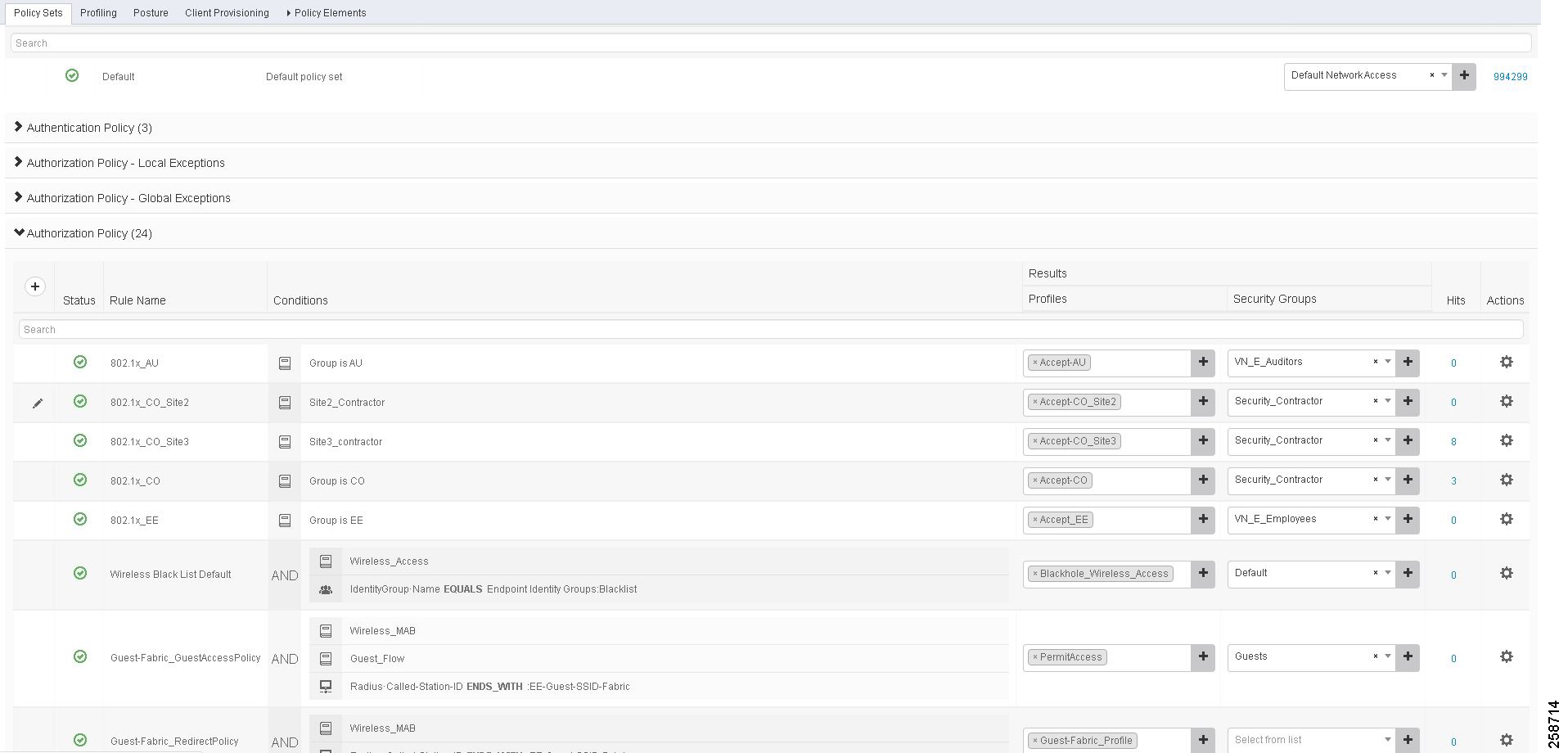
The default policy can be designed based on the organization's specific security requirements. One option is to assign a default SGT like DEFAULT_GENERIC for classifying devices that do not meet any of the authorization policy conditions.
Authorization Profile
1.![]() In ISE, navigate to Policy > Policy Results.
In ISE, navigate to Policy > Policy Results.
2.![]() Click Authorization on the left panel and choose Authorization Profiles.
Click Authorization on the left panel and choose Authorization Profiles.
3.![]() Click Add to add a new profile or choose an existing one to modify.
Click Add to add a new profile or choose an existing one to modify.
4.![]() Provide a name and select Access Type. ACCESS_ACCEPT is selected by default.
Provide a name and select Access Type. ACCESS_ACCEPT is selected by default.
5.![]() Under Common Tasks, check the VLAN check box.
Under Common Tasks, check the VLAN check box.
6.![]() In ID/Name field enter ‘host pool subnet’ + ‘Virtual Network name’ in the following format: 10_102_115_0-BUILDING-VN. As an alternative, a friendly name can be assigned to the VLAN in Cisco DNA Center to simplify policy deployment in ISE. This is especially useful on multi-site deployments where the same policy needs to be reused but the host pool subnet varies depending the fabric site. Details about configuring the Friendly name will be covered later in this document, refer to Creating Extended Nodes Host Pool.
In ID/Name field enter ‘host pool subnet’ + ‘Virtual Network name’ in the following format: 10_102_115_0-BUILDING-VN. As an alternative, a friendly name can be assigned to the VLAN in Cisco DNA Center to simplify policy deployment in ISE. This is especially useful on multi-site deployments where the same policy needs to be reused but the host pool subnet varies depending the fabric site. Details about configuring the Friendly name will be covered later in this document, refer to Creating Extended Nodes Host Pool.
Figure 8 Authorization Profile
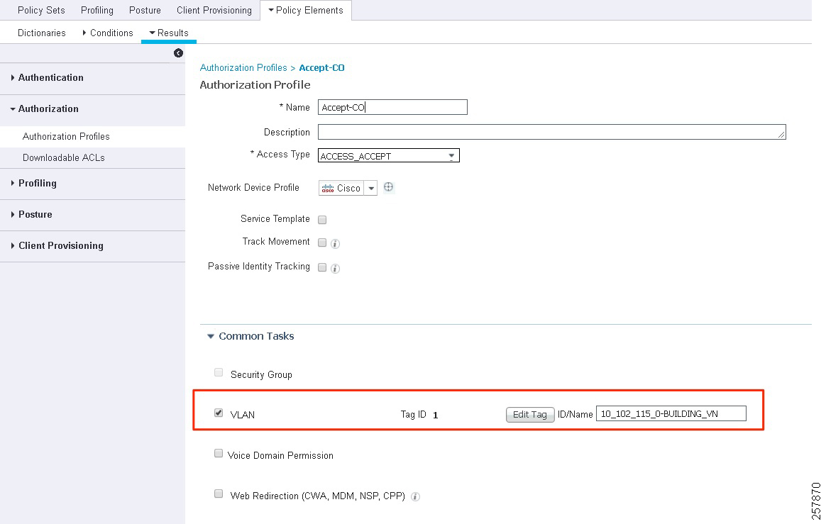
Tip: Cisco Catalyst 9800 Series Wireless Controllers support VLAN to VNID mapping as of IOS-XE version 17.2.1. This feature is required to dynamically assign the endpoint to the correct subnet using the VLAN field on the authorization profile.
Policy Enforcement over IP Transit
When the Cisco DNA Center provisions the SDA fabric, the Fabric Edge (FE) devices have enforcement enabled automatically using the cts role-based enforcement and cts role-based enforcement vlan-list vlans commands. However, enforcement is not enabled on the border. Flows between the FE devices and devices outside the fabric which traverse the border are not restricted by default.
Depending on the border device type, the best place to enforce Fabric to non-Fabric flows, if required, may be in the Fusion device. Device type, function, load and scale required need to be considered when deciding where best to enforce. In this implementation, there is no enforcement at the border.
Unlike the SD-Access Transit connection between sites where SGT information is carried in the VXLAN header, an IP Transit connection between sites is not guaranteed to carry inline tags. Devices external to the fabric that carry traffic between two sites connected via IP Transit may not have TrustSec enabled, may not be TrustSec capable, or may belong to the service provider. To maintain micro-segmentation, the border nodes need to re-apply the source tag lost in transit.
Although Cisco TrustSec inline tagging can be supported when VRF-Lite is used for network connectivity, it not supported in MPLS environments where both Label Distribution Protocol and Cisco TrustSec are required on the interface. This is not a configuration limitation but an architectural one, whereby the label Forwarding Information Base (FIB) is used for next-hop processing, unlike the standard FIB, and hence the SGT and its IP association cannot be learned. In MPLS networks it is necessary to use SXP to “propagate” or communicate the IP-to-SGT mapping across the MPLS portion of the network.
In this implementation, ISE is used to share the IP-to-SGT mappings with the border nodes. This information is populated in ISE dynamically or statically. ISE has the IP-to-SGT mappings of endpoints that it has authenticated and authorized to share with the the border nodes.
In the case of statically assigned endpoints, this mapping needs to be manually configured in ISE. The border nodes on either end of the transit link must have the mappings used in the site on the opposite end, as well as any mappings for devices in the shared services subnet.
The IP-to-SGT mappings can be learned by the border using the following methods:
1.![]() Use SXP to send the IP-to-SGT mapping from ISE to the border.
Use SXP to send the IP-to-SGT mapping from ISE to the border.
2.![]() Use SXP to share statically added mappings from a network device to the border.
Use SXP to share statically added mappings from a network device to the border.
3.![]() Use the CLI on the border to manually add mappings.
Use the CLI on the border to manually add mappings.
This document will focus on method 1 to keep user-configured IP-to-SGT static mappings in one central place along with any dynamic mappings learned from RADIUS sessions. The following table summarizes how IP-to-SGT mappings are added to ISE using method 1.
Configuration to Support IP Transit SGT Propagation
This section details the required configuration to support SGT propagation when connecting fabric sites using IP transit.
Enabling SXP and Global Settings on ISE
This section assumes that policy has already been created in Cisco DNA Center.
1.![]() During setup and sync of Cisco DNA Center and ISE, SXP should have been enabled. Verify that is has been enabled in ISE at Administration > System > Deployment > (hostname of SXP node)
During setup and sync of Cisco DNA Center and ISE, SXP should have been enabled. Verify that is has been enabled in ISE at Administration > System > Deployment > (hostname of SXP node)
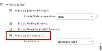
Note: We recommend that you run the SXP service on a standalone node. In a distributed deployment, this would be a PSN node that handles SXP connections, and does not handle RADIUS authentications, sometimes referred to as an SXPSN.
Note the following points while using the SXP service:
■![]() If the RADIUS accounting updates are too frequent (for example, around six to eight accounting updates in a few seconds), sometimes the accounting update packet might be dropped and SXP might not receive the IP-to-SGT binding.
If the RADIUS accounting updates are too frequent (for example, around six to eight accounting updates in a few seconds), sometimes the accounting update packet might be dropped and SXP might not receive the IP-to-SGT binding.
■![]() After upgrading from a previous version of ISE, SXP does not start automatically. After the upgrade, you must change the SXP password and restart the SXP process.
After upgrading from a previous version of ISE, SXP does not start automatically. After the upgrade, you must change the SXP password and restart the SXP process.
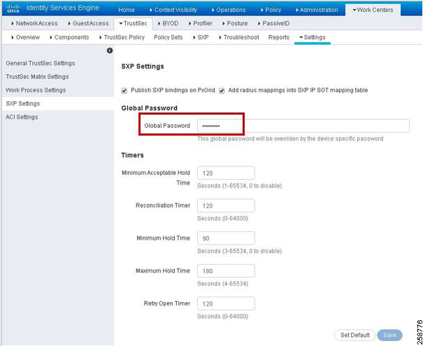
■![]() Navigate to Work Centers > TrustSec > Settings > SXP Settings and enter a Global Password to be matched when adding the other end of the SXP connection on the border device.
Navigate to Work Centers > TrustSec > Settings > SXP Settings and enter a Global Password to be matched when adding the other end of the SXP connection on the border device.
(Optional) Configuration of TrustSec Enforcement on Border Node
When the TrustSec device learns of a Scalable Group mapping, it will request policies from ISE associated with that SGT. It will only do this, however, if enforcement is enabled on the border. Cisco DNA Center does not enable this enforcement, but it can be added manually.
Note : In this implementation, there is no enforcement at the Fabric border, but this section was added for reference if the use case requires enforcing traffic leaving the fabric site.
For border routers, enter the global configuration command cts role-based enforcement on the border node to enable enforcement.
C9500-N15-1(config)#cts role-based enforcement
If the border is a switch, enforcement also needs to be enabled on the appropriate VLANs using the cts role-based enforcement vlan-list vlan command.
C9500-N15-1(config)#cts role-based enforcement
C9500-N15-1(config)#cts role-based enforcement vlan-list vlan
Tip : Even if enforcement is not enabled on the border node, IP-to-SGT mappings can still be used to re-tag incoming traffic with source SGTs to allow enforcement at another policy enforcement point if source tags were removed on the IP Transit link.
Using ISE and SXP to send IP-to-SGT mappings to the Fabric Border
Before proceeding with configuration of SXP, it is best to test connectivity between the IP-Transit connected sites. For this to occur you may need to redistribute routes between routing protocols and leak routes between the user created VNs/VRFs and the Global Routing Table (GRT). This is a manual configuration on the Fusion device.
Configuring ISE SXP devices with multiple Virtual Networks
Before the SXP Device is added, the IP address of the border node must be reachable from ISE and it must be in the VN/VRF where enforcement is needed. Therefore, if IP-to-SGT mappings are used for enforcement in the EMPLOYEE_VN and the BUILDING_VN, an IP from each of these Virtual Networks on the border node must be added as an SXP connection to ISE.
In the DEFAULT_VN, the management IP address of the device can be used for the SXP connection. If no policy enforcement is expected in the DEFAULT_VN, an SXP connection from that VRF is unnecessary. Within each user-created Virtual Network there are addresses that may also be used.
There are two IP addresses which could be used on the border node within a Virtual Network. One is the IP address towards the Fusion router, and the other is the Anycast IP address that Cisco DNA Center provisions into the Virtual Network when host pools are created. If you have multiple host pools in a Virtual Network or redundant Fusion routers, there will be more than one option. Either IP can be used if Route Leaking and Redistribution have been configured such that ISE can communicate with that IP address. Identify one IP address from each Virtual Network on the border node to use for the SXP connection to ISE.
Tip : Cisco ISE does not support multiple SXP session bindings with same IP address.
The configuration example below is trimmed for length.
C9500-N15-1#show run | sec interface
ip address 10.102.114.1 255.255.255.255
description vrf interface to External router
ip address 172.17.172.13 255.255.255.252
Before proceeding, ensure that the chosen IP address can contact ISE. Remember to source ICMP traffic from the VRF where the chosen source IP address resides.
C9500-N15-1#ping vrf BUILDING_VN 10.1.3.75 source 10.102.114.1
Adding SXP Domains
Before adding SXP Devices to ISE in an environment with multiple VRFs, SXP Domains need to be understood. An SXP Domain is a collection of SXP devices, and the administrator can direct a subset of IP-to-SGT mappings to each group. This can help enable a VRF awareness when distributing mappings by manually grouping SXP connections based on their VRF of origin into an SXP Domain and then assigning the appropriate IP-to-SGT mappings to the SXP Domain. This differs from deploying static IP-to-SGT mappings via SSH because that function cannot support distribution of mappings to multiple VRFs. Static IP-to-SGT mappings are assigned a domain when they are created. All IP-to-SGT mappings learned through RADIUS authentications are automatically added to the default domain but can be reassigned to a different domain using SXP Domain filters.
SXP connections from network devices with multiple VRFs will require a connection from an IP address in each Virtual Network back to ISE. We can use SXP Domains and SXP Domain filters to limit mappings sent from ISE to the network device to what is necessary for that Virtual Network. If not, the entire mapping table will be shared with each SXP connection peer from the network device.
To create an SXP domain in ISE:
1.![]() Navigate to Work Centers > TrustSec > SXP > SXP Devices.
Navigate to Work Centers > TrustSec > SXP > SXP Devices.
2.![]() Click the Assign SXP Domain link, even if no SXP devices are present.
Click the Assign SXP Domain link, even if no SXP devices are present.
3.![]() On the SXP Domain Assignment window, click the Create New SXP Domain link.
On the SXP Domain Assignment window, click the Create New SXP Domain link.
Figure 11 SXP Domain Assignment

4.![]() In the Enter VPN Name field that appears, enter a name for the new domain.
In the Enter VPN Name field that appears, enter a name for the new domain.
Create an SXP Domain for each Virtual Network where policy is enforced because we will group enforcement device SXP connections and mappings based on VN membership. These domains are selected when adding SXP Devices to ISE and can also be assigned or modified after the devices have been added.
Add an SXP Device on ISE
1.![]() Choose Work Centers > TrustSec > SXP > SXP Devices.
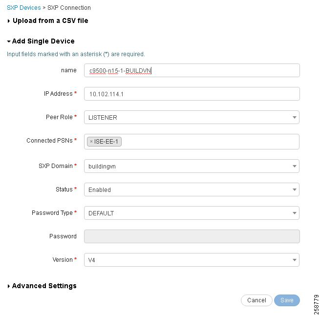
Choose Work Centers > TrustSec > SXP > SXP Devices.
- Click Upload from a CSV file link to add the SXP devices using a CSV file. Browse and select the CSV file, and then click the Upload button. You can also download the CSV template file, fill in the details of the devices that you want to add, and upload the CSV file.
- Click the Add Single Device link to add the device details manually for each SXP device. Enter the name, IP address, SXP role (listener, speaker, or both), password type, SXP version, and connected PSNs for the peer device. You must also specify the SXP domain to which the peer device is connected.
4.![]() (Optional) Click the Advanced Settings link and enter the following details:
(Optional) Click the Advanced Settings link and enter the following details:
- Minimum Acceptable Hold Time—Specify the time, in seconds, a speaker will send keep-alive messages for keeping the connection alive. The valid range is from 1 to 65534.
- Keep-Alive Timer—Used by a speaker to trigger the dispatch of keep-alive messages during intervals when no other information is exported via update messages. The valid range is from 0 to 64000.
Configure SXP on the Border Node
1.![]() On the border node, configure SXP. It must be added using the IP address chosen previously as the source address and the VRF/VN name must be specified using the vrf keyword
On the border node, configure SXP. It must be added using the IP address chosen previously as the source address and the VRF/VN name must be specified using the vrf keyword
C9500-N15-1(config)#cts sxp enable
C9500-N15-1(config)#cts sxp default passwordmypass
C9500-N15-1(config)#cts sxp connection peer 10.1.3.75 source 10.102.114.1 password default mode
local listener hold-time 0 0 vrf BUILDING_VN
2.![]() Repeat these steps for an IP address in each VN for each enforcement device. If there are two Virtual Networks that require policy enforcement, then two SXP connections are made with ISE from the enforcement device.
Repeat these steps for an IP address in each VN for each enforcement device. If there are two Virtual Networks that require policy enforcement, then two SXP connections are made with ISE from the enforcement device.
Verify SXP Connection
Once the SXP device has been added to ISE in Work Centers > TrustSec > SXP > SXP Devices and the SXP configuration has been added to the border node by CLI, verify the status of the SXP connection.
To verify the SXP connection status, navigate to Work Centers > TrustSec > SXP > SXP Devices and review the Status column for the recently added device. The device status may be listed as PENDING_ON for several moments before moving to the ON state.
The connection status can also be verified on the CLI of the border node using the show cts sxp connections command. Remember to specify the VRF of the source IP address.
C9500-N15-1#show cts sxp connections vrfBUILDING_VN
The SXP entry at the top of the listing should be ‘Enabled’, and the Conn Status entry halfway down the output should be ‘On’. This method is a quick way to verify the connection. See the Troubleshooting SXP Devices section for example output.
Creating IP-to-SGT Static Mappings in ISE
Static IP-to-SGT mappings are necessary to enforce policies over IP Transit due to extended nodes not authenticating endpoints with ISE. The host onboarding settings of the port determine the host pool and SGT for the endpoint. Without authenticating the endpoint to ISE, ISE has no knowledge of the IP-to-SGT mapping. The switch also reapplies SGTs from its IP-to-SGT mappings that were removed when leaving the fabric on the IP Transit link.
Before you begin, ensure that the Scalable Group Tags needed for the mapping have been created.
To create a new static mapping:
1.![]() Navigate to Work Centers > TrustSec > Components > IP SGT Static Mapping.
Navigate to Work Centers > TrustSec > Components > IP SGT Static Mapping.
3.![]() Enter the IP address or hostname for a single device or use CIDR notation for subnets.
Enter the IP address or hostname for a single device or use CIDR notation for subnets.
4.![]() The Map to SGT individually radio button is chosen by default.
The Map to SGT individually radio button is chosen by default.
–![]() Choose the SGT name in the SGT drop-down list.
Choose the SGT name in the SGT drop-down list.
–![]() Enter the SXP Domain name in the Send to SXP Domain field. If left blank, the default domain is used.
Enter the SXP Domain name in the Send to SXP Domain field. If left blank, the default domain is used.
–![]() From the Deploy to devices drop-down list, select the grouping of devices to which the mapping should be deployed.
From the Deploy to devices drop-down list, select the grouping of devices to which the mapping should be deployed.
The Deploy to devices field, if used, deploys mappings over SSH to the group of devices selected if CLI credentials have been entered during device creation under Administration > Network Devices > (Device Name) > Advanced TrustSec Settings > Device Configuration Deployment. This method of deploying IP-to-SGT mappings is not able to handle distribution to multiple VRFs.
If the Add to a mapping group radio button is chosen, the IP address can be assigned to a mapping group which is a user-defined, named group with pre-selected options for the SGT, Send to SXP Domain, and Deploy to devices fields.
Tip : Using SSH from ISE to push the mapping cannot be used for policy enforcement over Virtual Networks, because that ISE function is not VRF-aware. When creating the IP-to-SGT mapping, choosing a device name or device group from the Deploy to devices drop-down list indicates the user wants to push the static mapping via SSH to the device CLI.
Add an SXP Domain Filter
When static IP-to-SGT mappings are created, they are assigned an SXP domain and distributed to SXP devices or connections assigned to that domain. Unlike statically created mappings, all IP-to-SGT mappings ISE learns from RADIUS session information are placed in the default SXP domain. This becomes problematic when there are multiple SXP connections per enforcement device originating from different VNs/VRFs. IP-to-SGT mapping for an endpoint that is assigned to a Virtual Network during authentication need to be sent to the SXP connection on the enforcement device that resides in the same Virtual Network.
If traffic sourced from an endpoint in the BUILDING_VN leaves that fabric border and crosses the MPLS network and re-enters the border at the remote site, its IP-to-SGT mapping must be shared to the SXP connection within the same VN so it can be re-tagged with its source SGT information. If certain mappings, learned via RADIUS, should be moved to a different SXP domain, an SXP Domain Filter will need to be added.
Before creating Domain Filters, navigate to Work Centers > TrustSec > Settings > SXP Settings. Check the add radius mappings into SXP IP-to-SGT mapping table check box. This allows ISE to add IP-to-SGT mappings learned via RADIUS session to the SXP IP-to-SGT mapping table, otherwise only static mappings will be shared by SXP.
Tip : If static IP-to-SGT mappings have been created and shared via SXP that cover all host subnets in your network, then sharing RADIUS-learned IP-to-SGT mappings and creating SXP Domain Filters may be unnecessary because the static IP-to-SGT mapping will be enough to reapply source tags to traffic that matches the static mapping. You can view all the mappings known to ISE (including static mappings and session mappings) on the Work Centers > TrustSec > SXP > All SXP Mappings page.
By default, session mappings learned from the network devices are sent only to the default VPN group. You can create SXP domain filters to send the mappings to different SXP domains (VPNs). To add an SXP domain filter:
1.![]() Navigate to Work Centers > TrustSec > SXP > All SXP Mappings.
Navigate to Work Centers > TrustSec > SXP > All SXP Mappings.
2.![]() Click the Add SXP Domain Filter button.
Click the Add SXP Domain Filter button.
–![]() Enter the subnet details. The session mappings of the network devices with IP addresses from this subnet are sent to the SXP domain (VPN) that is selected in the SXP Domain field.
Enter the subnet details. The session mappings of the network devices with IP addresses from this subnet are sent to the SXP domain (VPN) that is selected in the SXP Domain field.
–![]() From the SGT drop-down list, choose an SGT. The SGT mappings will be sent to the SXP domain that is selected in the SXP Domain field.
From the SGT drop-down list, choose an SGT. The SGT mappings will be sent to the SXP domain that is selected in the SXP Domain field.
–![]() If you have specified both Subnet and SGT, the session mappings that match this filter are sent to the SXP domain that you have selected in the SXP Domain field.
If you have specified both Subnet and SGT, the session mappings that match this filter are sent to the SXP domain that you have selected in the SXP Domain field.
–![]() Choose the SXP domain to which the mappings must be sent.
Choose the SXP domain to which the mappings must be sent.
You can also update or delete the SXP domain filters. To update a filter, click the Manage SXP Domain Filter button, check the check box next to the filter that you want to update, and then click the Edit button. To delete a filter, check the check box next to the filter that you want to delete, and then click Trash > Selected.
Security Troubleshooting
This section uses the command runner functionality on Cisco DNA Center to get information in edge nodes. To use command runner, complete the following steps:
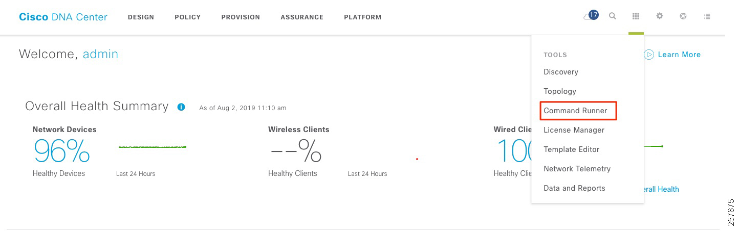
1.![]() From the Cisco DNA Center home page, click Command Runner in Tools. The Command Runner window displays:
From the Cisco DNA Center home page, click Command Runner in Tools. The Command Runner window displays:
Figure 13 Launch Command Runner
2.![]() On Search by Device IP, select the devices you want to run the commands on. A Device List with your selection displays.
On Search by Device IP, select the devices you want to run the commands on. A Device List with your selection displays.
3.![]() Type the commands you want to run; you can type up to five commands.
Type the commands you want to run; you can type up to five commands.
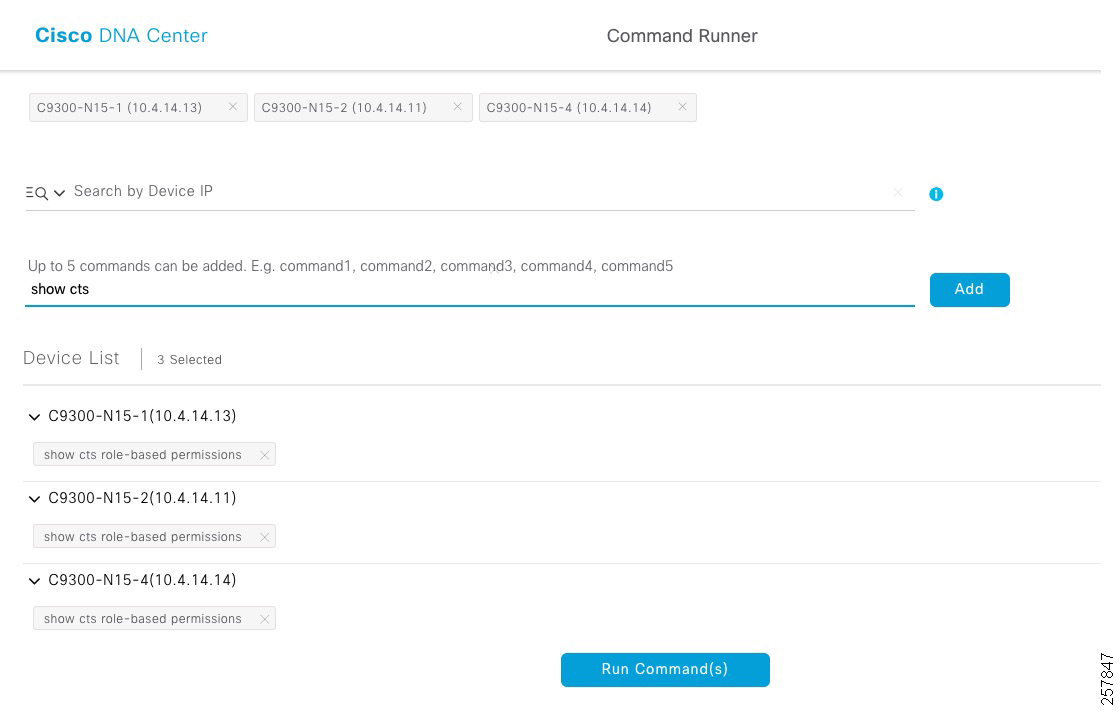
4.![]() Click Run Command(s). If successful, a Command(s) executed successfully message displays.
Click Run Command(s). If successful, a Command(s) executed successfully message displays.
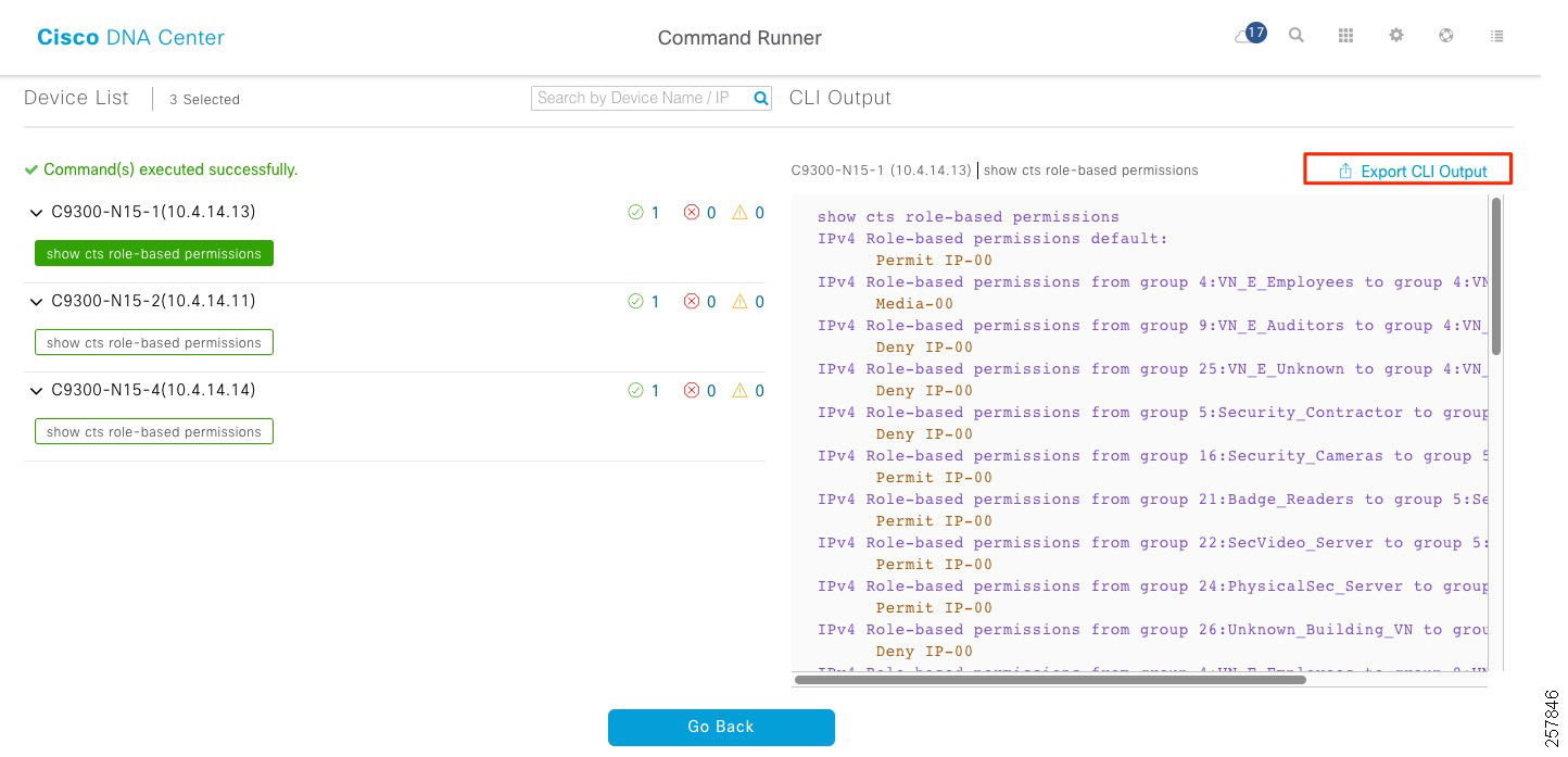
5.![]() Click the command displayed beneath the device name to view the command output. The complete command output is displayed in the Command Runner window.
Click the command displayed beneath the device name to view the command output. The complete command output is displayed in the Command Runner window.
6.![]() If required, output can be exported to a file using the Export CLI Output option.
If required, output can be exported to a file using the Export CLI Output option.
Figure 15 Command Runner Output
TrustSec Troubleshooting on Edge Switch and Policy Extended Node
This section contains a list of useful commands to troubleshoot TrustSec on the edge switches.
■![]() show cts environment-data—Displays TrustSec environment data, useful for identifying scalable groups pushed to the device.
show cts environment-data—Displays TrustSec environment data, useful for identifying scalable groups pushed to the device.
■![]() show cts role-based sgt-map vrf VIRTUAL_NETWORK all—Shows IP to SGT mapping in the edge node. This command is useful on the edge node. It will display mappings for endpoints connected directly or through an AP or extended node.
show cts role-based sgt-map vrf VIRTUAL_NETWORK all—Shows IP to SGT mapping in the edge node. This command is useful on the edge node. It will display mappings for endpoints connected directly or through an AP or extended node.
■![]() show cts role-based counters—Provides information on the exit edge node about SGACL being applied. In the example, allowed packet counters are shown in green and denied packet counters are shown in red.
show cts role-based counters—Provides information on the exit edge node about SGACL being applied. In the example, allowed packet counters are shown in green and denied packet counters are shown in red.
■![]() show cts role-based permissions—Shows SGACL configured in ISE and pushed to the device.
show cts role-based permissions—Shows SGACL configured in ISE and pushed to the device.
■![]() show cts rbacl—Shows contracts downloaded to the device
show cts rbacl—Shows contracts downloaded to the device
Troubleshooting SXP Devices
If an SXP device is added to ISE, it will remain in the “Pending_ON” state for a few minutes before moving to the “ON” state. This is the fastest method to confirm the SXP connection state.
show cts sxp connections —Shows SXP connection information including connection status, peer IP address, and source IP address. The vrf keyword must be used to see connection in any non-default VRFs.
If the connection remains in the “off” or “pending_on” state, check that the password and source IP address used for the connection matches the source IP address and password configured in ISE for the SXP device. Also check that SXP is enabled on the device with the cts sxp enable command.
C9500-N15-1#show cts sxp connections vrfBUILDING_VN
Default Key-Chain Name: Not Applicable
Connection retry open period: 120 secs
Retry open timer is not runningPeer-Sequence traverse limit for export: Not Set
Peer-Sequence traverse limit for import: Not Set
----------------------------------------------
Conn capability : IPv4-IPv6-Subnet
TCP conn password: default SXP password
Duration since last state change: 25:04:07:19 (dd:hr:mm:sec)
Total num of SXP Connections = 1
Show cts sxp sgt-map —Shows IP-to-SGT mappings received via an SXP peer. If mappings are sent in a non-default SXP domain, use the vrf keyword to specify the appropriate VRF and display IP-to-SGT mappings. This command only shows IP-to-SGT mappings learned by the SXP connection, and any static mappings configured from the CLI will not be displayed here. For all IP-to-SGT map information on the device use the show cts role-based sgt-map all command as discussed in the previous section, remembering to specify VRF, if necessary.
C9500-N15-1#show cts sxp sgt-map vrfBUILDING_VN
SXP Node ID(generated):0xAC10AF01(172.16.175.1)
IPv4,SGT: <10.102.114.0/24, 16:Security_Cameras>
IPv4,SGT: <10.102.115.0/24, 5:Security_Contractor>
IPv4,SGT: <10.102.116.0/24, 21:Badge_Readers>
Peer Seq: 0A01034B,IPv4,SGT: <10.102.124.0/24, 16:Security_Cameras>source : SXP;
IPv4,SGT: <10.102.125.0/24, 5:Security_Contractor>
IPv4,SGT: <10.102.126.0/24, 21:Badge_Readers>
IPv4,SGT: <10.102.134.0/24, 16:Security_Cameras>
IPv4,SGT: <10.102.135.0/24, 5:Security_Contractor>
IPv4,SGT: <10.102.136.0/24, 21:Badge_Readers>
source : SXP;Peer IP : 10.1.3.75;
Dynamic SGT Classification Troubleshooting
To ensure that an endpoint has received the correct SGT from Cisco ISE, log in to the ISE primary Admin node:
1.![]() Navigate to Operations > Radius > Live Logs. On the Live Logs page, filter for the endpoint in question. Live log entries for the endpoint should be visible. Under the Identity column, #CTSREQUEST# displays any time SGT information is downloaded to the switch.
Navigate to Operations > Radius > Live Logs. On the Live Logs page, filter for the endpoint in question. Live log entries for the endpoint should be visible. Under the Identity column, #CTSREQUEST# displays any time SGT information is downloaded to the switch.
2.![]() Click the Details icon for the log entry under the Details column. Near the bottom of the page in the Results section of the output, there are several entries for cisco-av-pairs. The av-pair cts:security-group-tag=00-0000 contains the tag number issued to the endpoint.
Click the Details icon for the log entry under the Details column. Near the bottom of the page in the Results section of the output, there are several entries for cisco-av-pairs. The av-pair cts:security-group-tag=00-0000 contains the tag number issued to the endpoint.
On the Live Logs page, SGT information can also be found in the Authorization Profiles column. If the network device received SGT information along with the authorization profile for the endpoint, the name of the SGT will be displayed next to the Authorization Profile name.
On the policy extended nodes, details of the device session can be seen using command runner. The following command provides information on all access sessions of devices connected to the switch.
For a detailed view use the following command. It provides device details, assigned VLAN and assigned SGT.
Provisioning
This chapter explains how to configure the fabric edge node and host onboarding page to support extended nodes and policy extended nodes. It also explains how to connect IE switches to the fabric network using the Cisco SD-Access Extension for IoT. Included are instructions to provision the network for endpoint onboarding.
Configure Fabric Edge
An extended node is connected to a fabric edge using EtherChannel. When using no authentication as the global setting for the fabric, the port channel gets created automatically once the industrial switch is connected to the network. If any other authentication template is selected, a port channel needs to be created manually. Authentication options are explained in Host Onboarding.
1.![]() In the Cisco DNA Center dashboard, navigate to PROVISION > Fabric.
In the Cisco DNA Center dashboard, navigate to PROVISION > Fabric.
3.![]() Choose the fabric site from the Fabric-Enabled Sites.
Choose the fabric site from the Fabric-Enabled Sites.
4.![]() Click the Fabric Infrastructure tab and select the fabric edge node. A window with the device name as the title displays.
Click the Fabric Infrastructure tab and select the fabric edge node. A window with the device name as the title displays.
5.![]() Select the Port Channel tab.
Select the Port Channel tab.
6.![]() Click +Create Port Channel.
Click +Create Port Channel.
7.![]() Select the interfaces to be used.
Select the interfaces to be used.
8.![]() Under Select Protocol, click the PAGP radio button. PAGP is supported on IE3400 starting on IOS-XE version 17.1.1s.
Under Select Protocol, click the PAGP radio button. PAGP is supported on IE3400 starting on IOS-XE version 17.1.1s.
Figure 16 Create Port-channel on Fabric Edge
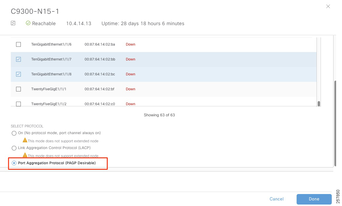
Host Onboarding
The final required step to provision an SD-Access fabric is host onboarding. Although it is covered in the Cisco Software-Defined Access Deployment Guide, it requires special mention in this document because it enables extended node functionality.
Host onboarding comprises four distinct steps and is configured under the Provision > Fabric > Host Onboarding tab for a fabric site:
Define Authentication Template
The first step is to select the authentication template. These templates are predefined in the Cisco DNA Center and are pushed down to all devices that are operating as edge nodes within a site. It is mandatory to complete this step first, an authentication template must be defined before host pool creation.
Authentication templates deploy certain interface-level commands on the downstream (access) ports of all edge nodes. By default, access ports are considered all copper ports operating as switchports (as opposed to routed ports) on the edge nodes. These interface-level commands are port-based network access control configurations that validate a connected endpoint before it can connect to a network.
There are four supported authentication templates:
These templates are based on the AAA Phased Deployment Implementation Strategy of High Security mode, Low Impact mode, Monitor mode, and No Authentication mode. Hovering over each option in Cisco DNA Center provides information about the authentication template. To support dynamic authentication on access ports make sure an option other than No authentication is chosen.
https://www.cisco.com/c/en/us/td/docs/solutions/Enterprise/Security/TrustSec_1-99/Phased_Deploy/Phased_Dep_Guide.html#wp392247
To select an authentication template:
1.![]() In the Cisco DNA Center dashboard, navigate to PROVISION > Fabric.
In the Cisco DNA Center dashboard, navigate to PROVISION > Fabric.
3.![]() Select the fabric site from the Fabric-Enabled Sites.
Select the fabric site from the Fabric-Enabled Sites.
4.![]() Click the Host Onboarding tab.
Click the Host Onboarding tab.
5.![]() Under Select Authentication Template, choose Closed Authentication.
Under Select Authentication Template, choose Closed Authentication.
Tip: An authentication template can be overwritten on a per-port basis. In this guide, we selected closed authentication because it provides a higher level of security for edge ports.
Create Host Pools
The second step is to bind the IP address pools to the VNs. Once bound, these components are referred to collectively as host pools. Multiple IP address pools can be associated with the same VN.
When a host pool is created, a subnet in the form of a reserved IP address pool is bound to a VN. From the perspective of device configuration, Cisco DNA Center creates the VRF definition on the fabric nodes, creates a switch virtual interface (SVI) or loopback interface (on switches and routers, respectively), defines these interfaces to forward for the VRF, and gives the IP address defined as the gateway for the reserved pool.
For the Extended Enterprise deployment, you create host pools for extended nodes, access points, and endpoints. In the security section we mentioned SGTs can be associated to a host pool. This is done when creating a host pool. Also, a friendly name for the host pool can be assigned during creation to be used on the VLAN field of ISE authorization profile.
Creating Extended Nodes Host Pool
Extended nodes and APs are special cases in the fabric. Extended Nodes and APs are connected to edge nodes like an endpoint, but they are part of the fabric infrastructure. Because of this, their traffic pattern is unique. Extended nodes receive a DHCP address via the overlay network. To accommodate this traffic flow, the extended node subnet, which is in the Global Routing Table (GRT), is associated with the overlay network. The Cisco DNA Center GUI calls this special overlay network associated with the GRT the INFRA_VN.
The Infrastructure Virtual Network (INFRA_VN) overlay is intended to represent devices that are part of the network infrastructure but associate and connect to the network in a similar method to endpoints: in other words, directly connected to the downstream ports of an edge node. Both APs and extended nodes (SD-Access extension for IoT) are part of the INFRA_VN.
Tip: INFRA_VN, while labeled as a VN in the GUI because it is part of the overlay network, is not provisioned as a VRF definition in the network. It is not truly a VRF and routes for the INFRA_VN are in the GRT.
1.![]() Under the Host Onboarding tab, under Virtual Networks, select INFRA_VN.
Under the Host Onboarding tab, under Virtual Networks, select INFRA_VN.
2.![]() In the Edit Virtual Network: INFRA_VN pane, click + to add a new pool.
In the Edit Virtual Network: INFRA_VN pane, click + to add a new pool.
3.![]() From the IP drop-down menu, choose the IP pool name(s) to be associated to the VN. The drop-down menu shows IP pools reserved for the fabric site.
From the IP drop-down menu, choose the IP pool name(s) to be associated to the VN. The drop-down menu shows IP pools reserved for the fabric site.
4.![]() Under Pool Type, choose Extended.
Under Pool Type, choose Extended.
Figure 17 Extended Node Host Pool
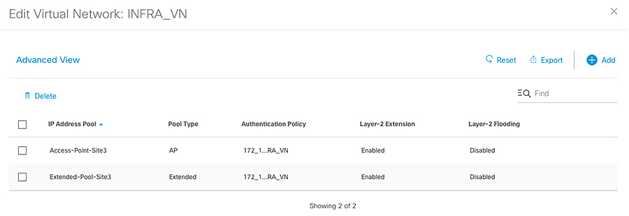
Creating AP Host Pool
AP host pools are also created in the INFRA_VN by performing the following steps:
1.![]() Under the Host Onboarding tab, under Virtual Networks, select INFRA_VN.
Under the Host Onboarding tab, under Virtual Networks, select INFRA_VN.
2.![]() In the Edit Virtual Network: INFRA_VN pane click + to add a new pool.
In the Edit Virtual Network: INFRA_VN pane click + to add a new pool.
3.![]() From the IP drop-down menu, choose the IP pool name(s) to be associated to the VN. The drop-down menu shows IP pools reserved for the fabric site.
From the IP drop-down menu, choose the IP pool name(s) to be associated to the VN. The drop-down menu shows IP pools reserved for the fabric site.
Creating Host Pools for Endpoint Onboarding
1.![]() Under the Host Onboarding tab, choose the VN for the endpoints. In this CVD, one pool is used for building devices such as IP cameras and badge readers.
Under the Host Onboarding tab, choose the VN for the endpoints. In this CVD, one pool is used for building devices such as IP cameras and badge readers.
2.![]() In the Edit Virtual Network pane, click + to add a new pool.
In the Edit Virtual Network pane, click + to add a new pool.
3.![]() From the IP drop-down menu, choose the IP pool name(s) to be associated to the VN. The drop-down menu shows IP pools reserved for the fabric site.
From the IP drop-down menu, choose the IP pool name(s) to be associated to the VN. The drop-down menu shows IP pools reserved for the fabric site.
4.![]() (Optional) Assign a friendly name to the host pool on the Authorization Policy field as shown in the picture below. The friendly name can be used in ISE authorization profile to simplify policy creation workflow.
(Optional) Assign a friendly name to the host pool on the Authorization Policy field as shown in the picture below. The friendly name can be used in ISE authorization profile to simplify policy creation workflow.
5.![]() (Optional) From the Scalable Group drop-down list choose the SGT for the specific host pool. This step is needed for micro- segmentation because policy tagging is done at the edge using IP subnet to SGT mapping. The step is optional on deployments with policy extended nodes only but it is needed to enable micro-segmentations on deployments with extended nodes.
(Optional) From the Scalable Group drop-down list choose the SGT for the specific host pool. This step is needed for micro- segmentation because policy tagging is done at the edge using IP subnet to SGT mapping. The step is optional on deployments with policy extended nodes only but it is needed to enable micro-segmentations on deployments with extended nodes.
6.![]() From the Traffic drop-down menu, choose Data.
From the Traffic drop-down menu, choose Data.
7.![]() Check the relevant options below. Make sure to check Wireless Pool if required by wireless endpoints.
Check the relevant options below. Make sure to check Wireless Pool if required by wireless endpoints.
Tip: Authentication policy and Scalable group options cannot be modified once the pool is created.
Figure 18 Host Pool for Endpoints
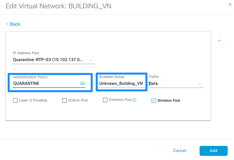
Tip: After IP host pools are added to a VN, the VN background will change to blue as shown in Figure 19. Hovering over the VN will display how many pools are assigned.
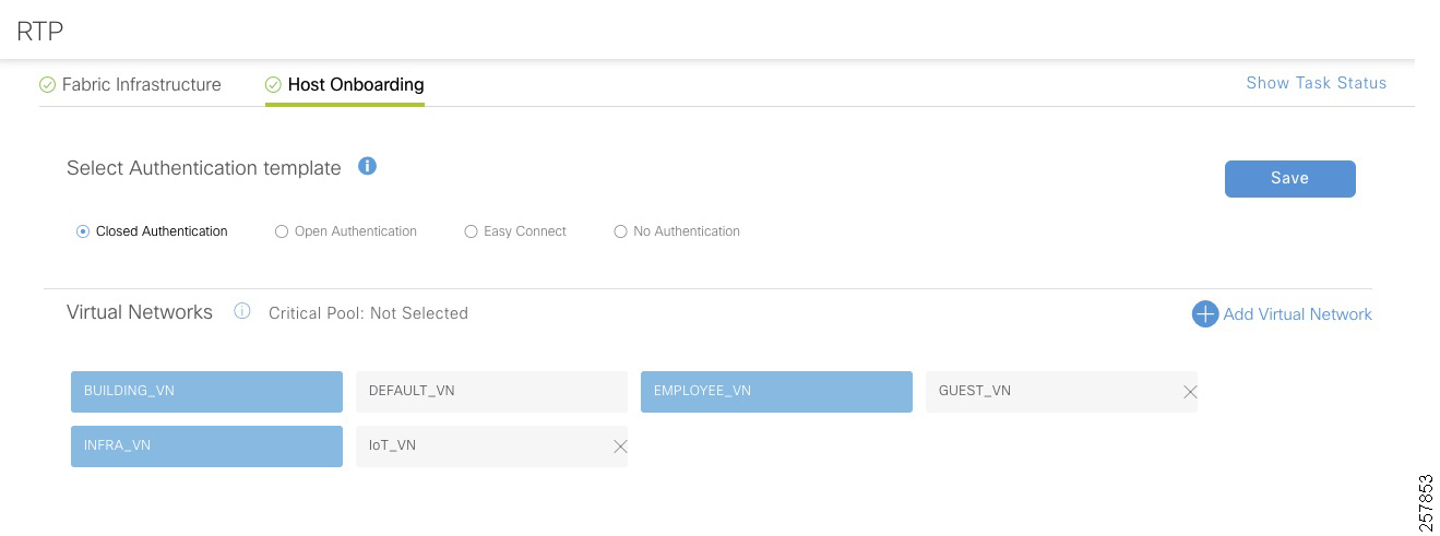
Wireless SSID Configuration
This step binds an SSID to an IP address pool and is required for SD-Access in wireless scenarios. Each SSID for a fabric site must be assigned an IP address pool so that wireless hosts are associated with the correct subnet when connecting to the wireless network.
1.![]() Click the Host Onboarding tab.
Click the Host Onboarding tab.
2.![]() Under Wireless SSIDs, from the Address Pool drop-down menu, choose the IP address pool for the SSID.
Under Wireless SSIDs, from the Address Pool drop-down menu, choose the IP address pool for the SSID.
3.![]() (Optional) Under Scalable Group, choose an SGT. In this CVD, an unknown tag was used by default. The tag will be replaced by ISE after endpoint completes authorization process.
(Optional) Under Scalable Group, choose an SGT. In this CVD, an unknown tag was used by default. The tag will be replaced by ISE after endpoint completes authorization process.
4.![]() Repeat Steps 1 through 3 for every SSID.
Repeat Steps 1 through 3 for every SSID.
Figure 20 Host Onboarding Wireless SSID
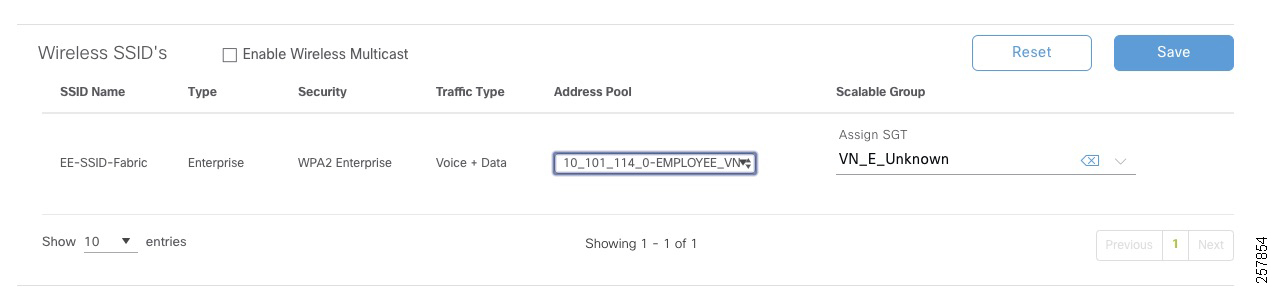
Select Port Assignment
The last step is to selectively overwrite default port configuration. This step is required in the following scenarios:
■![]() Configuring a port for an AP if using closed authentication
Configuring a port for an AP if using closed authentication
■![]() Configuring a port-channel for extended nodes if using closed authentication
Configuring a port-channel for extended nodes if using closed authentication
Port Assignment for Access Points
Cisco DNA Center enables automatic onboarding of APs by provisioning a Cisco Discovery Protocol macro at the fabric edge nodes when the authentication template is set to No Authentication. If a different authentication template is used globally (for example, Closed Authentication), then the downstream switchport configurations on the edge nodes must be changed in the Cisco DNA Center.
1.![]() Under the Host Onboarding tab, choose the switch where the access point will be connected.
Under the Host Onboarding tab, choose the switch where the access point will be connected.
2.![]() Check the boxes for the appropriate ports to be used for APs.
Check the boxes for the appropriate ports to be used for APs.
4.![]() In the Port Assignment window, from the Connected Device Type drop-down menu, choose Access Point (AP).
In the Port Assignment window, from the Connected Device Type drop-down menu, choose Access Point (AP).
5.![]() Leave the default address pool selection and, from the Authentication Template drop-down list, choose No Authentication. If adding an AP to an extended node, No Authentication is selected by default.
Leave the default address pool selection and, from the Authentication Template drop-down list, choose No Authentication. If adding an AP to an extended node, No Authentication is selected by default.
7.![]() After all ports supporting APs have been chosen, under the Host Onboarding tab, click Save. Keep the default Now selection, and then click Apply.
After all ports supporting APs have been chosen, under the Host Onboarding tab, click Save. Keep the default Now selection, and then click Apply.
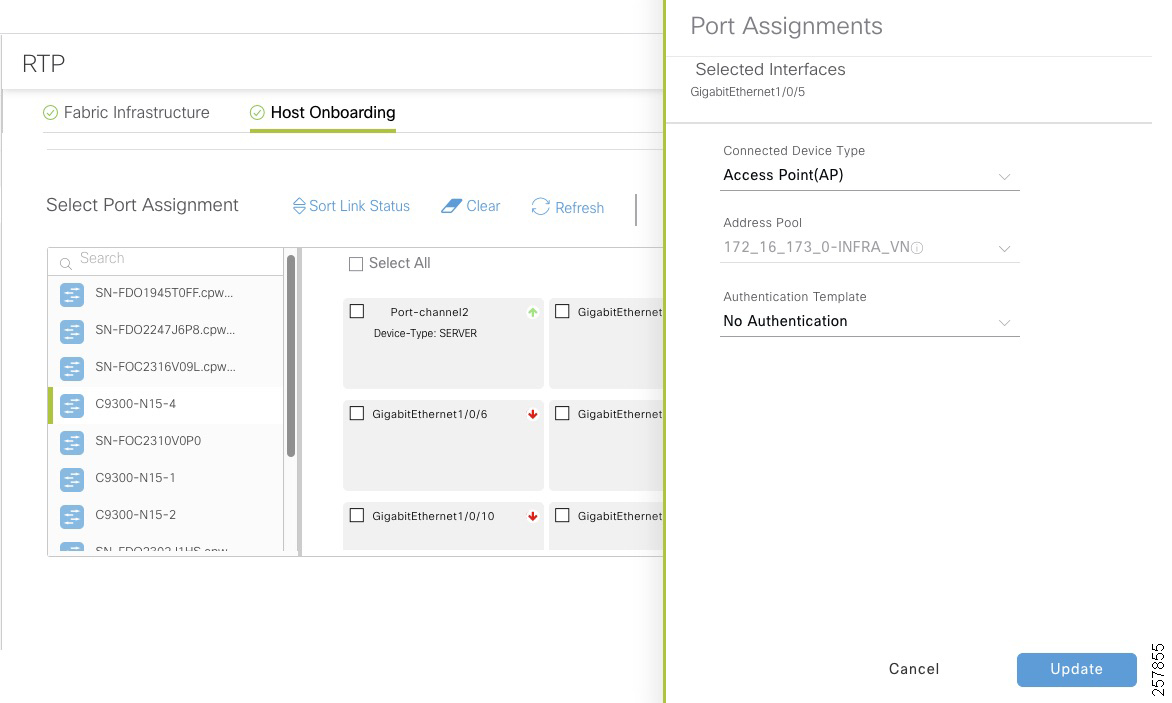
Tip: The configuration is not pushed to the switch until the configuration is saved.
Port Assignment for Extended Nodes Connected to Edge
Like APs, extended nodes are onboarded automatically when the authentication template is set to No Authentication. When a different authentication template is used globally (for example, Closed Authentication), then the downstream switchport configurations on the edge nodes must be changed in the Cisco DNA Center.
1.![]() Under the Host Onboarding tab, choose the fabric edge switch (for example, C9300).
Under the Host Onboarding tab, choose the fabric edge switch (for example, C9300).
2.![]() Check the box for the appropriate port channel to be used for extended nodes.
Check the box for the appropriate port channel to be used for extended nodes.
4.![]() In the Port Assignment window, from the Connected Device Type drop-down menu, choose Extended Node.
In the Port Assignment window, from the Connected Device Type drop-down menu, choose Extended Node.
6.![]() After all ports supporting extended nodes have been selected, under the Host Onboarding tab, click Save. Keep the default Now selection, and then click Apply.
After all ports supporting extended nodes have been selected, under the Host Onboarding tab, click Save. Keep the default Now selection, and then click Apply.
Figure 22 Extended Node Assignment
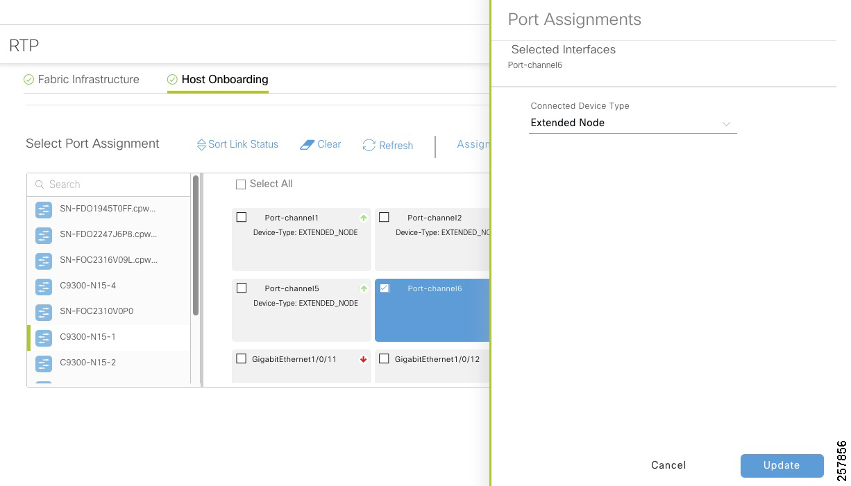
Port Assignment for Server Ports
1.![]() Under the Host Onboarding tab, choose a switch.
Under the Host Onboarding tab, choose a switch.
2.![]() Check the box for the appropriate interface to be used for the server.
Check the box for the appropriate interface to be used for the server.
4.![]() On the Port Assignment window, from the Connected Device Type drop-down menu, choose Server.
On the Port Assignment window, from the Connected Device Type drop-down menu, choose Server.
6.![]() Under the Host Onboarding tab, click Save. Keep the default Now selection, and then click Apply.
Under the Host Onboarding tab, click Save. Keep the default Now selection, and then click Apply.
Port Assignment for Endpoints Requiring Static Configuration
1.![]() Under the Host Onboarding tab, choose the extended node switch.
Under the Host Onboarding tab, choose the extended node switch.
2.![]() Check the box for the appropriate interface to be used for the wired endpoint.
Check the box for the appropriate interface to be used for the wired endpoint.
4.![]() On the Port Assignment window, from the Connected Device Type drop-down menu, choose User Devices.
On the Port Assignment window, from the Connected Device Type drop-down menu, choose User Devices.
5.![]() (Optional) From the Address Pool drop-down menu, choose the appropriate address pool. This option may be used for endpoints with static IP address.
(Optional) From the Address Pool drop-down menu, choose the appropriate address pool. This option may be used for endpoints with static IP address.
6.![]() (Optional) From the Voice Pool drop-down menu, choose the appropriate voice pool.
(Optional) From the Voice Pool drop-down menu, choose the appropriate voice pool.
7.![]() (Optional) Choose authentication option from the Authentication Template drop-down menu. This will overwrite global authentication template on the port.
(Optional) Choose authentication option from the Authentication Template drop-down menu. This will overwrite global authentication template on the port.
9.![]() Under the Host Onboarding tab, click Save. Keep the default Now selection, and then click Apply.
Under the Host Onboarding tab, click Save. Keep the default Now selection, and then click Apply.
Figure 23 Endpoint Port Assignment
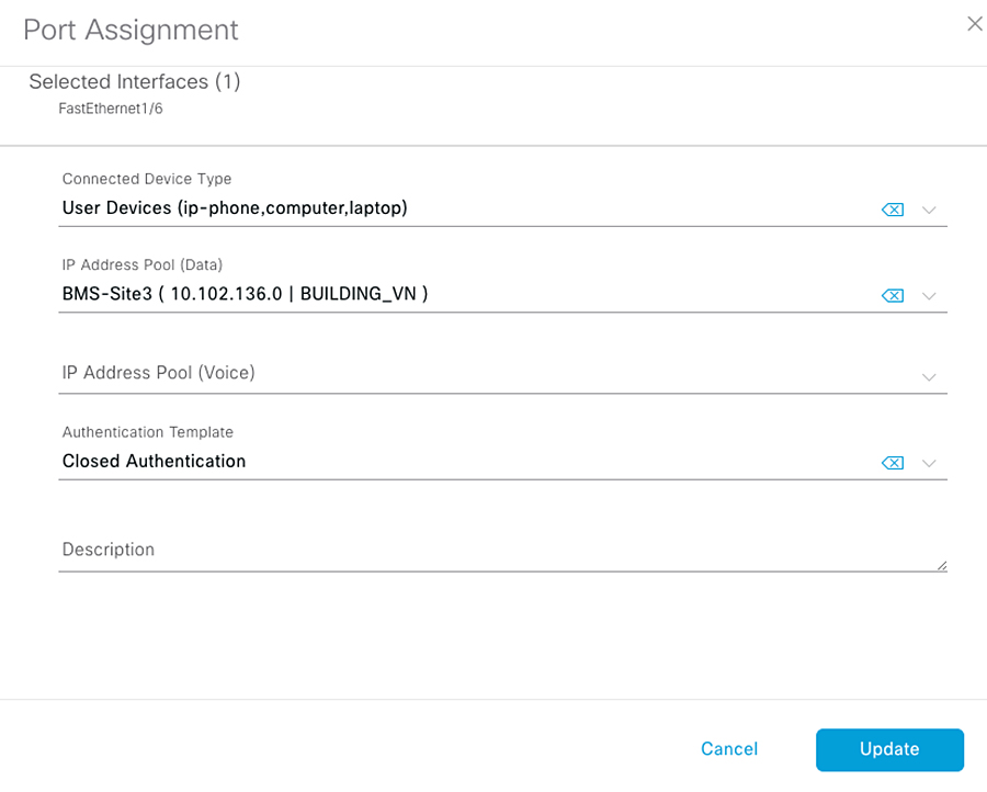
Adding an Extended Node to Cisco SD-Access Network
After the port channel has been created (if using closed authentication) and host onboarding has been configured as explained in the previous section, the extended node is deployed using zero-touch Plug and Play (PnP).
Cisco industrial switches running IOS or IOS-XE software have a PnP agent embedded in the software that communicates with the PnP deployment server. The PnP agent runs on a device if no startup configuration exists, such as when a device is powered on for the first time or reset to factory default. The PnP agent attempts to discover the PnP deployment server via DHCP or the Domain Name System (DNS). Cisco DNA Center serves as the PnP server for the Extended Enterprise deployment.
Adding a Policy Extended Node to Cisco SD-Access Network
Adding a policy extended node follows same process than an extended node. After the port channel has been created (if using closed authentication) and host onboarding has been configured as explained in the previous section, the policy extended node is deployed using zero-touch Plug and Play (PnP) if it meets the following requirements:
■![]() Switch is a Catalyst IE3400 or IE3400H
Switch is a Catalyst IE3400 or IE3400H
■![]() Switch has DNA Advance license
Switch has DNA Advance license
■![]() Switch is running IOS-XE 17.1.1s or newer. Note that even if policy extended Node is provisioned on IOS-XE versions 17.1.1s and older, it is recommended you use IOS-XE version 17.3.1 because this version has critical fixes to guarantee TrustSec enforcement.
Switch is running IOS-XE 17.1.1s or newer. Note that even if policy extended Node is provisioned on IOS-XE versions 17.1.1s and older, it is recommended you use IOS-XE version 17.3.1 because this version has critical fixes to guarantee TrustSec enforcement.
PnP Requirements for DHCP Discovery
■![]() DHCP server with option 43 configured pointing to the Cisco DNA Center.
DHCP server with option 43 configured pointing to the Cisco DNA Center.
■![]() DHCP server must accept the Cisco vendor-specific option 60 case-sensitive value ciscopnp.
DHCP server must accept the Cisco vendor-specific option 60 case-sensitive value ciscopnp.
DHCP option 43 consists of a string value that is configured as follows on a Cisco router CLI that is acting as a DHCP server:
The option 43 string has the following components, delimited by semi-colons:
■![]() 5A1N;—Specifies the DHCP sub-option for PnP, active operation, version 1, no debug information. It is not necessary to change this part of the string.
5A1N;—Specifies the DHCP sub-option for PnP, active operation, version 1, no debug information. It is not necessary to change this part of the string.
■![]() B2;—IP address type, B2 stands for IPv4, B1 should be used for hostname.
B2;—IP address type, B2 stands for IPv4, B1 should be used for hostname.
■![]() Ixxx.xxx.xxx.xxx;—IP address or hostname of the Cisco DNA Center controller (following a capital letter i). In this example, the IP address is 172.19.45.222.
Ixxx.xxx.xxx.xxx;—IP address or hostname of the Cisco DNA Center controller (following a capital letter i). In this example, the IP address is 172.19.45.222.
■![]() Jxxxx—Port number to use to connect to the Cisco DNA Center controller. In this example, the port number is 80. The default is port 80 for HTTP and port 443 for HTTPS.
Jxxxx—Port number to use to connect to the Cisco DNA Center controller. In this example, the port number is 80. The default is port 80 for HTTP and port 443 for HTTPS.
■![]() K4;—Transport protocol to be used between the device and the controller, use K4 for HTTP (default) or K5 for HTTPS.
K4;—Transport protocol to be used between the device and the controller, use K4 for HTTP (default) or K5 for HTTPS.
For more information, refer to the Cisco Digital Network Architecture Center User Guide.
PnP Requirements for DNS Discovery
■![]() Domain name option configured on DHCP server
Domain name option configured on DHCP server
■![]() DNS server option configured on DHCP server
DNS server option configured on DHCP server
■![]() PnP server (Cisco DNA Center) resolves to PnP deployment server IP in DNS
PnP server (Cisco DNA Center) resolves to PnP deployment server IP in DNS
■![]() IP helper address should be configured on the distribution switch
IP helper address should be configured on the distribution switch
Bringing Up a Policy Extended Node or an Extended Node
Power on the device if it has no previous configuration. If the node device has configurations, use the write erase command to remove previous configuration and reload the extended node device. Cisco DNA Center adds the extended node device to the inventory and assigns the same site as the fabric edge. The device is then added to the fabric. Now the extended node device is onboarded and ready to be managed.
Once the configuration is complete, the node appears in the fabric topology with a tag (X) indicating that it is an extended node or policy extended node.
Figure 24 Extended Node or Policy Extended Node Added to the Fabric
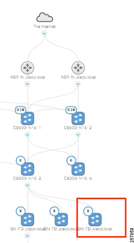
Migrating an Extended Node to a Policy Extended Node
If your network has a Catalyst IE3400 with an older software version operating as extended node, upgrading the version won’t enable policy extended node functionality. Node re-provision is required. Follow these steps.
1.![]() Go to Provision > Fabric and choose the fabric site.
Go to Provision > Fabric and choose the fabric site.
2.![]() Choose the extended node and click Remove From Fabric. Confirm removal.
Choose the extended node and click Remove From Fabric. Confirm removal.
3.![]() Click Save on the main page.
Click Save on the main page.
4.![]() Once the device is removed from the fabric, go to Provision > Devices > Inventory.
Once the device is removed from the fabric, go to Provision > Devices > Inventory.
5.![]() Choose the device and click Actions > Inventory > Delete Device
Choose the device and click Actions > Inventory > Delete Device
6.![]() Go to ISE and select Administration > Network Resources > Network Devices
Go to ISE and select Administration > Network Resources > Network Devices
7.![]() Choose the device and click Delete. Confirm removal.
Choose the device and click Delete. Confirm removal.
8.![]() If a port channel was created on the fabric edge using other than PGAP option, it needs to be deleted. Follow steps 8-10 to delete and recreate the port channel.
If a port channel was created on the fabric edge using other than PGAP option, it needs to be deleted. Follow steps 8-10 to delete and recreate the port channel.
9.![]() Go to Provision > Fabric and choose the fabric site. Go to Host Onboarding > Port Assignment. Click the fabric edge and choose the port channel. Click Clean, then click Save.
Go to Provision > Fabric and choose the fabric site. Go to Host Onboarding > Port Assignment. Click the fabric edge and choose the port channel. Click Clean, then click Save.
10.![]() Go to Provision > Fabric and choose the fabric site and fabric edge. Go to the Port Channel tab and delete the port channel.
Go to Provision > Fabric and choose the fabric site and fabric edge. Go to the Port Channel tab and delete the port channel.
11.![]() Create the Port channel as described in Configure Fabric Edge.
Create the Port channel as described in Configure Fabric Edge.
12.![]() From the device CLI, delete all configuration and reload.
From the device CLI, delete all configuration and reload.
Extended Node or Policy Extended Node Troubleshooting
If errors in the workflow exist while configuring an extended node, an error notification is displayed as a banner on the topology window, as shown in Figure 25.
Figure 25 Extended Node Workflow Error
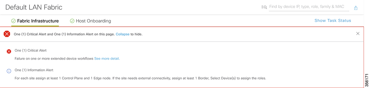
Click See More Details to view the error. The Task Monitor window displays the extended node task status. Click See Details to see the cause of error and possible solution, as shown in Figure 26.
Figure 26 Extended Node Workflow Error Details
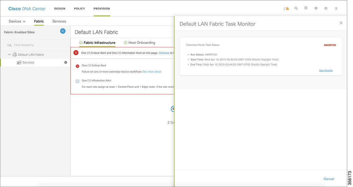
The device console can also provide some helpful information. The following console output is provided as example of a successful flow. We have highlighted some important lines for reference.
Device Not Starting the Plug and Play Process
■![]() Verify the device has no configuration. If the switch is a brownfield device, use the following commands to clear the switch configuration (spacing intentional for copy/paste):
Verify the device has no configuration. If the switch is a brownfield device, use the following commands to clear the switch configuration (spacing intentional for copy/paste):
■![]() Verify the PnP VLAN was created automatically on the switch. Before PnP starts, you should see a line for an interface VLAN pnp-VLAN created on the IE switch:
Verify the PnP VLAN was created automatically on the switch. Before PnP starts, you should see a line for an interface VLAN pnp-VLAN created on the IE switch:
■![]() If that is not the case, verify that the EtherChannel is created on the fabric edge and IP Host Pool was created for extended nodes on INFRA_VN.
If that is not the case, verify that the EtherChannel is created on the fabric edge and IP Host Pool was created for extended nodes on INFRA_VN.
■![]() If the switch gets a DHCP IP address, but the PnP process has not started, check that option 43 is configured on the DHCP server and that Option 60 is supported on the DHCP server.
If the switch gets a DHCP IP address, but the PnP process has not started, check that option 43 is configured on the DHCP server and that Option 60 is supported on the DHCP server.
■![]() If a PnP timeout occurs while contacting Cisco DNA Center, verify that Cisco DNA Center is reachable from the PnP VLAN.
If a PnP timeout occurs while contacting Cisco DNA Center, verify that Cisco DNA Center is reachable from the PnP VLAN.
Navigate to Provision > Devices > Plug and Play and click the device name. Under the History tab, review error details and click Info to get more information.
Provisioning Wireless Access Points
This guide assumes that the administrator already discovered, upgraded and configured redundancy on the WLC. For more information on those tasks, refer to the CVD Software-Defined Access Medium and Large Site Fabric Provisioning.
In order to add APs to the network, you must do the following:
■![]() Add DHCP scope for APs with option 43 pointing to WLC.
Add DHCP scope for APs with option 43 pointing to WLC.
■![]() Make sure the IP address pool for APs was created in Cisco DNA Center with the correct DHCP server and associated to INFRA_VN in the host onboarding configuration.
Make sure the IP address pool for APs was created in Cisco DNA Center with the correct DHCP server and associated to INFRA_VN in the host onboarding configuration.
■![]() Ensure the AP is connected to the Power over Ethernet (PoE) port on an IE switch or a power injector.
Ensure the AP is connected to the Power over Ethernet (PoE) port on an IE switch or a power injector.
Follow this procedure to provision an AP:
1.![]() Navigate to the Cisco DNA Center dashboard. Under PROVISION > Devices > Inventory, choose the WLC and then in the Actions > Inventory drop-down menu, choose Resync Device. The APs associated with the WLC are added to the inventory without waiting for an inventory refresh.
Navigate to the Cisco DNA Center dashboard. Under PROVISION > Devices > Inventory, choose the WLC and then in the Actions > Inventory drop-down menu, choose Resync Device. The APs associated with the WLC are added to the inventory without waiting for an inventory refresh.
Figure 27 Resync WLC for AP Provision
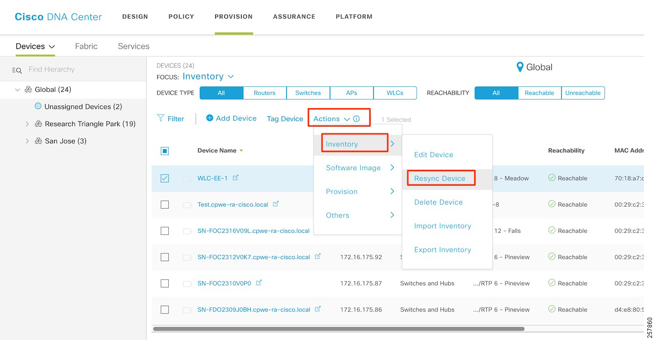
2.![]() Navigate to PROVISION > Devices > Inventory and choose the APs being added. From the Actions drop-down menu, choose Provision.
Navigate to PROVISION > Devices > Inventory and choose the APs being added. From the Actions drop-down menu, choose Provision.
3.![]() On the Provision Devices page, assign the APs to a floor (the floor should be managed by a WLC), and then click Next. For RF Profile, choose TYPICAL and then click Next.
On the Provision Devices page, assign the APs to a floor (the floor should be managed by a WLC), and then click Next. For RF Profile, choose TYPICAL and then click Next.
4.![]() At the Summary page, click Deploy. In the slide-out panel, leave the default selection of Now, and then click Apply and acknowledge any warnings about reboots.
At the Summary page, click Deploy. In the slide-out panel, leave the default selection of Now, and then click Apply and acknowledge any warnings about reboots.
Endpoint Onboarding
At this point, the network is ready for endpoint onboarding, provided DHCP pools have been created for endpoints. You can connect endpoints to industrial switches or wirelessly to outdoor APs using the fabric SSID. The endpoint should receive the appropriate SGT and policies. If the endpoint is not able to connect, you can use Client Health page to diagnose issues.
Review the following required configurations to help diagnose endpoint onboarding issues:
■![]() A DHCP scope for endpoints exists.
A DHCP scope for endpoints exists.
■![]() The DHCP server is reachable from the host IP pool. If not, check the fusion router configuration.
The DHCP server is reachable from the host IP pool. If not, check the fusion router configuration.
■![]() If the endpoint uses 802.1x authentication, the user should exist in the identity store configured in policy.
If the endpoint uses 802.1x authentication, the user should exist in the identity store configured in policy.
■![]() For wireless endpoints, if the SSID is not available, verify the WLC and APs were provisioned successfully.
For wireless endpoints, if the SSID is not available, verify the WLC and APs were provisioned successfully.
■![]() For wired endpoints, confirm the extended node was configured with the correct host pool.
For wired endpoints, confirm the extended node was configured with the correct host pool.
Provisioning a Software Image
The Cisco DNA Center allows you to push software images to the devices in your network. Prior to pushing the image, Cisco DNA Center checks the device for upgrade readiness, including device management status, SCP and HTTPS file transfer success, and disk space. If any pre-checks fail, you cannot perform the software image update. After the software image of the device is upgraded, the Cisco DNA Center checks the CPU usage, route summary, and so on, to ensure that the state of the network remains unchanged after the image upgrade.
The Cisco DNA Center also compares each device software image with the image that you have designated as golden for that specific device type. If a difference exists between the software image of the device and the golden image, then the Cisco DNA Center specifies the software image of the device as outdated. The upgrade readiness pre-checks will be triggered for those devices. If all the pre-checks are cleared, you can distribute the new image to the device and activate it. The activation of the new image requires a reboot of the device. This might interrupt the current network activity; if downtime is not feasible, you can schedule the process to a later time. If you have not designated a golden image for the device type, then the device's image cannot be updated.
Designating an Image as Golden
To upgrade a device in the Cisco DNA Center, it must have a golden image for its platform. Devices can be assigned a golden image by Family and Role. When an image is marked as golden, it can be tagged so that it applies to a subset of devices by network role. The default is tag is All, but you can select from the following options: Core, Distribution, Border Router, Unknown, and Access.
1.![]() Navigate to Design > Image Repository.
Navigate to Design > Image Repository.
2.![]() Navigate to the device family and then click the arrow next to the device family name to display a selection of images. Click the gray star under Golden Image to mark the image as golden.
Navigate to the device family and then click the arrow next to the device family name to display a selection of images. Click the gray star under Golden Image to mark the image as golden.
–![]() If the software image is already imported to the Cisco DNA Center (indicated by a blue trashcan in the Action column), the process to mark it as golden is faster.
If the software image is already imported to the Cisco DNA Center (indicated by a blue trashcan in the Action column), the process to mark it as golden is faster.
–![]() If the image is not imported (indicated by a gray trashcan in the Action column), the process will take longer because DNA attempts to import the image directly from Cisco.com.
If the image is not imported (indicated by a gray trashcan in the Action column), the process will take longer because DNA attempts to import the image directly from Cisco.com.
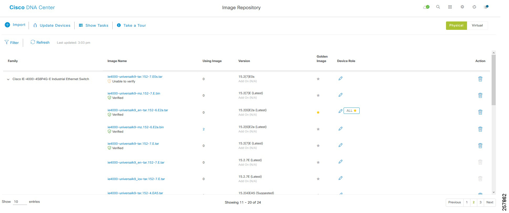
Upgrading Device to Golden Image
1.![]() To check if a device needs upgrading, navigate to Provision > Devices > Inventory.
To check if a device needs upgrading, navigate to Provision > Devices > Inventory.
2.![]() From the Focus drop-down menu, choose Software Images :
From the Focus drop-down menu, choose Software Images :
Figure 29 Change Focus to Software Images
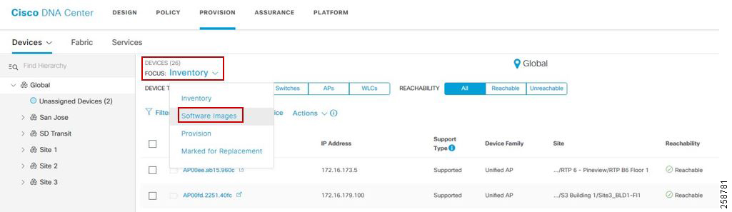
–![]() If a device shows as Outdated in the Software Image field, the device is not on the golden image and should be updated.
If a device shows as Outdated in the Software Image field, the device is not on the golden image and should be updated.
–![]() If there is a green check next to Outdated, the device has passed upgrade readiness checks and can be updated.
If there is a green check next to Outdated, the device has passed upgrade readiness checks and can be updated.
–![]() If there is a red check next to Outdated, the device has one or more issues in its readiness checks that must be resolved before the device can be updated.
If there is a red check next to Outdated, the device has one or more issues in its readiness checks that must be resolved before the device can be updated.
–![]() If Outdated is not displayed in the OS Image field for a device, it is either on the golden image or does not have a golden image specified in Design > Image Repository.
If Outdated is not displayed in the OS Image field for a device, it is either on the golden image or does not have a golden image specified in Design > Image Repository.
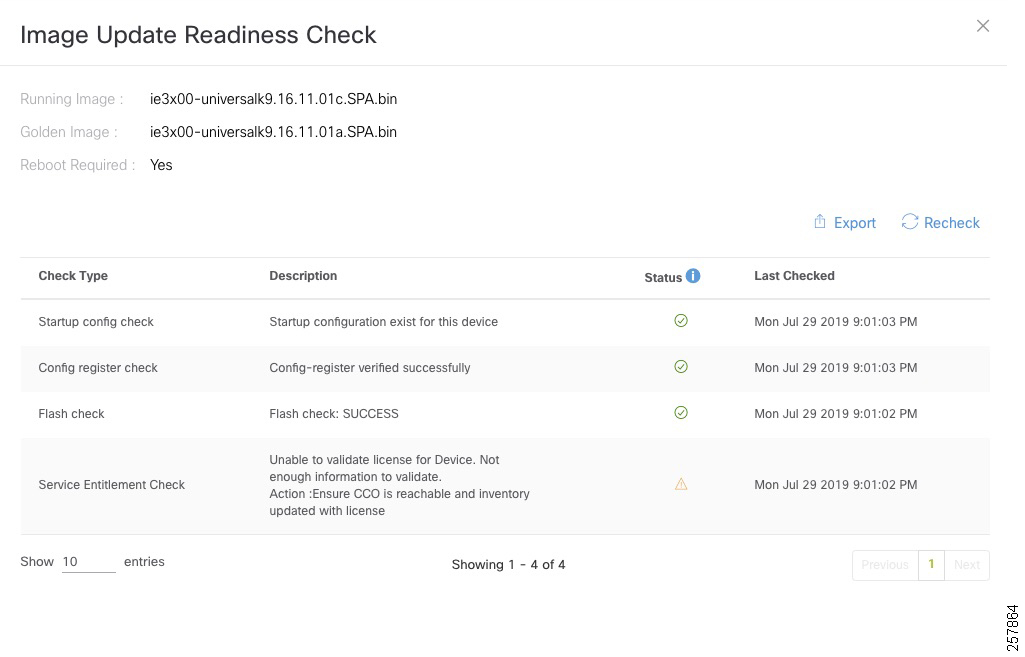
3.![]() (Only if necessary) For more detail on a device image upgrade readiness check, click Outdated. The Image Upgrade Readiness Check window displays. Near the top of the page, the current running image and the golden image are displayed. The Check Type field lists the readiness check, and a brief description is shown. One or more failures will prevent provisioning of an image and need to be corrected before the image can be updated. Warning triangles in the Status field indicate an issue, but do not affect the ability to provision a software image to the device. Once issues are corrected, proceed to the next step.
(Only if necessary) For more detail on a device image upgrade readiness check, click Outdated. The Image Upgrade Readiness Check window displays. Near the top of the page, the current running image and the golden image are displayed. The Check Type field lists the readiness check, and a brief description is shown. One or more failures will prevent provisioning of an image and need to be corrected before the image can be updated. Warning triangles in the Status field indicate an issue, but do not affect the ability to provision a software image to the device. Once issues are corrected, proceed to the next step.
Tip: If you correct an issue on a device, click Recheck, and if the issue still displays a failing status, resync the device on the Inventory page using Actions > Resync to update device details in the Cisco DNA Center. The change may be made on the device but might not have populated to the Cisco DNA Center.
4.![]() To begin the image update process, check the box next to one or more devices that require an image update and that have passed image update pre-checks. Then click Actions > Software Image > Update Image. The OS Update window will display.
To begin the image update process, check the box next to one or more devices that require an image update and that have passed image update pre-checks. Then click Actions > Software Image > Update Image. The OS Update window will display.
5.![]() At the Distribute step, click the Now radio button to begin distribution of the image immediately or the Later radio button to schedule distribution for later. Click Next to continue to the Activate step. During device sync, the Cisco DNA Center checks files in the target device file system. If the golden image is found in the file system, the distribution step will be skipped.
At the Distribute step, click the Now radio button to begin distribution of the image immediately or the Later radio button to schedule distribution for later. Click Next to continue to the Activate step. During device sync, the Cisco DNA Center checks files in the target device file system. If the golden image is found in the file system, the distribution step will be skipped.
6.![]() At the Activate step, check the box next to Schedule Activation after Distribution is Completed to reload the device and boot to the new image immediately after distribution is complete. Leave the box unchecked to pre-stage the image on the device and schedule image activation and device reload for a later time. Click Next to continue to the Confirm step.
At the Activate step, check the box next to Schedule Activation after Distribution is Completed to reload the device and boot to the new image immediately after distribution is complete. Leave the box unchecked to pre-stage the image on the device and schedule image activation and device reload for a later time. Click Next to continue to the Confirm step.
7.![]() At the Confirm step, review details entered for image upgrade. Click Confirm to submit.
At the Confirm step, review details entered for image upgrade. Click Confirm to submit.
When an image upgrade begins, it is possible to check upgrade status by going to Actions > Software Image > Image Update status. Click the drop-down arrow to the far right of each entry in Recent Tasks to display more information about distribution and activation operations.
Click Refresh periodically to see the most up-to-date information on job status. When complete, both the distribution operation and activate operation are preceded by green tick marks and the top-level status is successful.
Figure 31 Successful Software Upgrade

Once upgraded to the golden image, Outdated no longer appears in the Software Image field for the device in Inventory.
Tip: If activation fails for any reason, you can retry by creating a new task. The Cisco DNA Center will find the image in the device already and distribution step will be skipped.
Template Provisioning
Some features such as NetFlow and QoS policies on extended nodes and policy extended nodes are not configured as part of network automation. In these cases, template provisioning can be used. This section provides an overview of template provisioning.
Creating a Project
Projects are logically grouped templates. Unlike templates grouped in the Onboarding Configuration project that are only available during the Plug and Play process, Day-N templates are available for use during provisioning of a device in the Cisco DNA Center inventory. To create a project, do the following:
1.![]() From the Cisco DNA Center dashboard, choose Tools > Template Editor.
From the Cisco DNA Center dashboard, choose Tools > Template Editor.
2.![]() To create a new project, click + and then choose Create Project.
To create a new project, click + and then choose Create Project.
3.![]() In the Add New Project window, enter a unique name for the project and then click Add. The new project will appear in the left window.
In the Add New Project window, enter a unique name for the project and then click Add. The new project will appear in the left window.
Creating a Regular Template
1.![]() From the Cisco DNA Center dashboard, choose Tools > Template Editor.
From the Cisco DNA Center dashboard, choose Tools > Template Editor.
2.![]() Click + and choose Create Template.
Click + and choose Create Template.
3.![]() In the Add New Template window, click Regular Template.
In the Add New Template window, click Regular Template.
4.![]() Enter a name for the template.
Enter a name for the template.
5.![]() In the Project Name drop-down list, choose the correct project. Don’t select Onboarding Configuration because those are not visible when applying configuration to an already provisioned device.
In the Project Name drop-down list, choose the correct project. Don’t select Onboarding Configuration because those are not visible when applying configuration to an already provisioned device.
6.![]() (Optional) Choose an existing Tag from the list or create a new one. This can be used to apply templates to a group of devices in a site.
(Optional) Choose an existing Tag from the list or create a new one. This can be used to apply templates to a group of devices in a site.
7.![]() In the Select Device Type(s) window, drill down to platforms or grouping of platforms.
In the Select Device Type(s) window, drill down to platforms or grouping of platforms.
–![]() If all selections below a parent grouping are selected, a blue check is displayed in the check box.
If all selections below a parent grouping are selected, a blue check is displayed in the check box.
–![]() If some, but not all selections below a parent grouping are selected, a blue square is displayed.
If some, but not all selections below a parent grouping are selected, a blue square is displayed.
Choose all device platforms or groupings of platforms a template should apply to and click Back to Add New Template to return to the Add New Template window.
8.![]() Under Software Type, choose the software type for the template. Any template assigned to IOS software will also be available to IOS-XE and IOS-XR software devices, but templates made for IOS-XE and IOS-XR software will not be available to other IOS software devices. Once complete, click Add.
Under Software Type, choose the software type for the template. Any template assigned to IOS software will also be available to IOS-XE and IOS-XR software devices, but templates made for IOS-XE and IOS-XR software will not be available to other IOS software devices. Once complete, click Add.
10.![]() After the template is created, click the template name in the left window to edit. In the Template Editor window, enter any content for the template. The Cisco DNA Center uses the Velocity Templating Language (VTL) to allow the use of variables and logic statements to generate a configuration from a template. Appendix B: Sample Template used in CVD Verification, page 50 includes some template examples.
After the template is created, click the template name in the left window to edit. In the Template Editor window, enter any content for the template. The Cisco DNA Center uses the Velocity Templating Language (VTL) to allow the use of variables and logic statements to generate a configuration from a template. Appendix B: Sample Template used in CVD Verification, page 50 includes some template examples.
Note: In the Cisco DNA Center, configuration for devices is rendered via VTL. Velocity is a template programming language. In the Template Editor, configuration templates can be created using variables, macros, and loops that are then interpreted by Velocity to produce device configuration. All configurations are rendered on the Cisco DNA Center, and VTL does not have access to the current running configuration of the device.
11.![]() Click Actions and then click Save. The Cisco DNA Center will check for VTL syntax errors in the template. If errors exist, the template will not be saved.
Click Actions and then click Save. The Cisco DNA Center will check for VTL syntax errors in the template. If errors exist, the template will not be saved.
12.![]() To configure variables use the Form Editor icon on the top right. This view allows you to configure variable properties. Click Actions and then click Save.
To configure variables use the Form Editor icon on the top right. This view allows you to configure variable properties. Click Actions and then click Save.
13.![]() For the latest version of a template to be available in Design > Network Profiles, the template must be committed. Click Actions and then click Commit. In the Commit window, click Commit.
For the latest version of a template to be available in Design > Network Profiles, the template must be committed. Click Actions and then click Commit. In the Commit window, click Commit.
Creating a Composite Template
If you need to apply more than one template to the devices it is possible to use composite templates. Two or more regular templates are grouped together into a composite sequence template. You can create a composite sequential template for a set of templates, which are applied collectively to devices. The templates that you create can be added to a single composite template, which aggregates all the individual templates that you need. You must specify the order in which templates that are in the composite template are deployed to devices.
Furthermore, individual templates could contain a variable that could be changed if the template needs to be executed or not. For example, a composite template for an industrial switch could be created including a QoS template and a NetFlow template. A variable is used as flag in the template, when set to 1 the code in the template is executed. The administrator will be able to decide if configuring only one or two features. For this specific example check the Appendix section Appendix A Template Example.
Creating a Composite template is similar to the process described in Creating a Regular Template .
1.![]() Create a template as described in Creating a Regular Template . Select Composite instead of Regular for template type.
Create a template as described in Creating a Regular Template . Select Composite instead of Regular for template type.
2.![]() After creating the template, click the composite template that you created in the tree view pane.
After creating the template, click the composite template that you created in the tree view pane.
3.![]() In the Template Editor window, drag and drop templates from the tree view pane to create a sequence. The templates are deployed based on the order in which they are sequenced. You can change the order of templates in the Template Editor window. By default, the Applicable option is chosen in the View filter and only the applicable templates that can be added to the composite template are shown in the Template Editor window. You can choose the All option in the View filter to view all the templates. In the All option view, the templates that match the chosen device types and software version are marked by a plus icon. You can drag and drop templates that have the same device type, software type, and software version as that of the composite template.
In the Template Editor window, drag and drop templates from the tree view pane to create a sequence. The templates are deployed based on the order in which they are sequenced. You can change the order of templates in the Template Editor window. By default, the Applicable option is chosen in the View filter and only the applicable templates that can be added to the composite template are shown in the Template Editor window. You can choose the All option in the View filter to view all the templates. In the All option view, the templates that match the chosen device types and software version are marked by a plus icon. You can drag and drop templates that have the same device type, software type, and software version as that of the composite template.
4.![]() To abort the deployment process upon failure of the first template, select the first template in the Template Editor window and check the Abort sequence on targets if deployment fails check box.
To abort the deployment process upon failure of the first template, select the first template in the Template Editor window and check the Abort sequence on targets if deployment fails check box.
5.![]() From the Actions drop-down list, choose Commit to commit the template content.
From the Actions drop-down list, choose Commit to commit the template content.
Creating a Network Profile
Before a device can be provisioned using a template, it must be associated with a network profile and the profile must be assigned to a site.
1.![]() Navigate to Design > Network Profiles. Click Add Profile.
Navigate to Design > Network Profiles. Click Add Profile.
2.![]() Choose Switching to create a switching network profile.
Choose Switching to create a switching network profile.
3.![]() Enter a unique Profile Name. Choose Day-N Template(s) based on where the appropriate template is grouped.
Enter a unique Profile Name. Choose Day-N Template(s) based on where the appropriate template is grouped.
4.![]() To associate a template to the network profile, click +Add.
To associate a template to the network profile, click +Add.
5.![]() Under the Device Type column, drill down to a specific platform or group of devices. Only one platform type or one parent group of devices may be selected per field.
Under the Device Type column, drill down to a specific platform or group of devices. Only one platform type or one parent group of devices may be selected per field.
6.![]() (Optional) Choose a Device Tag to allow templates to be applied to a subset of devices.
(Optional) Choose a Device Tag to allow templates to be applied to a subset of devices.
7.![]() Under the Template column, choose the appropriate template.
Under the Template column, choose the appropriate template.
8.![]() (Optional) Click +Add to create another device type to template association within one network profile if needed.
(Optional) Click +Add to create another device type to template association within one network profile if needed.
Tip: If the expected template does not appear after choosing Device Type or Device Role, navigate back to Template Editor and ensure that the correct Device Type and Role have been added to the template. If changes have been made to the template and it still does not appear as a selection in Design > Network Profiles, ensure that the changes have been saved and committed.
The following figure shows a network profile with different templates applied to device with different tags.
Figure 32 Creating a Network Profile
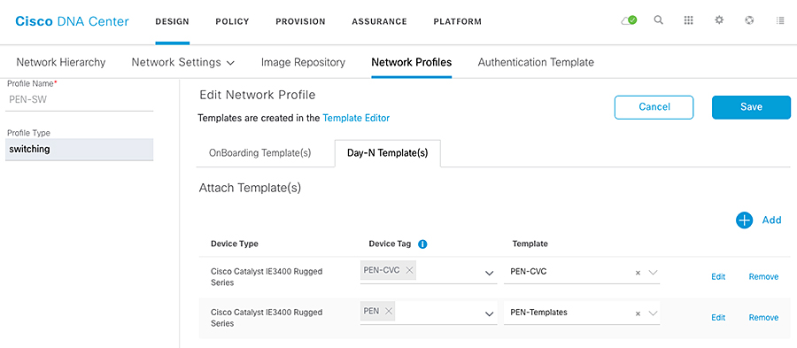
Associating Network Profile to a Site
Once the network profile has been created and has templates associated, it must be assigned to a site. On the Network Profiles page, click Assign Site. Click a site or sites where the network profile should be assigned. If a network profile is assigned to a site, any device provisioned at the site with a device type and role that matches a template association within the profile will have a template available during the provisioning step.
Provisioning a Template on a Device
1.![]() From the Cisco DNA Center dashboard, navigate to Provision > Devices > Inventory. The Device Inventory window displays.
From the Cisco DNA Center dashboard, navigate to Provision > Devices > Inventory. The Device Inventory window displays.
2.![]() Click the Device Inventory tab.
Click the Device Inventory tab.
3.![]() Click the check box adjacent to the device you want to provision.
Click the check box adjacent to the device you want to provision.
4.![]() From the Action drop-down list, choose Provision > Provision Device.
From the Action drop-down list, choose Provision > Provision Device.
5.![]() The Assign Site window displays. Click Next.
The Assign Site window displays. Click Next.
6.![]() If any Day-N templates are available for the device, the templates associated with the site through the network profile appear in the advanced configuration. Choose the device in the left pane. In the right pane, choose values for the attributes that are bound to source. If you want the template to be pushed to the device even when it was pushed previously check Push these templates even if its deployed before check box.
If any Day-N templates are available for the device, the templates associated with the site through the network profile appear in the advanced configuration. Choose the device in the left pane. In the right pane, choose values for the attributes that are bound to source. If you want the template to be pushed to the device even when it was pushed previously check Push these templates even if its deployed before check box.
To export the template variables into a CSV file while deploying the template, click Export in the right pane. You can use the CSV file to make necessary changes in the variable configuration and import it into Cisco DNA Center by clicking Import in the right pane.
7.![]() Click Next and then click Deploy.
Click Next and then click Deploy.
8.![]() Click Now or Later, then click Apply.
Click Now or Later, then click Apply.
9.![]() To see the deployment status, change to Provision view on the inventory page. The Provision Status column shows current status. Click a status for more details.
To see the deployment status, change to Provision view on the inventory page. The Provision Status column shows current status. Click a status for more details.
For more information in templates refer to https://www.cisco.com/c/en/us/td/docs/cloud-systems-management/network-automation-and-management/dna-center/1-3-3-0/user_guide/b_cisco_dna_center_ug_1_3_3_0/b_cisco_dna_center_ug_1_3_2_0_chapter_01000.html
Assurance
The Cisco DNA Center provides insights into enterprise networks by ingesting large amounts of data from network devices, clients, and sensors, and analyzing data. Many key performance metrics are measured and correlated to focus on highlighting issues and providing guided solutions.
Network devices must be discovered, added to the inventory, and exist in a managed state before the performance metrics of devices and clients can be viewed. Optionally, Assurance can integrate with ISE to provide more detail about connected clients. Various telemetry profiles can also be distributed to network devices to configure syslog, SNMP, and NetFlow.
Overall Health
Navigate to Assurance from the Cisco DNA Center dashboard. Assurance displays the Overall Health page, which summarizes the health of the entire enterprise network using graphs to highlight network device and client health. The default view is 24 hours, but can be toggled between 3 hours, 24 hours, and 7 days using the Last 24 hours drop-down menu near the top right of the page.
The Show toggle above the graphs can be used to turn the location pane on or off. This allows for listing devices and health status by site hierarchy, building, or geographic views. The Top 10 Issues pane follows the graphs of network device and client health. This pane aggregates and sorts issues by severity, giving a concise list of issues affecting the network with an instance count per issue.
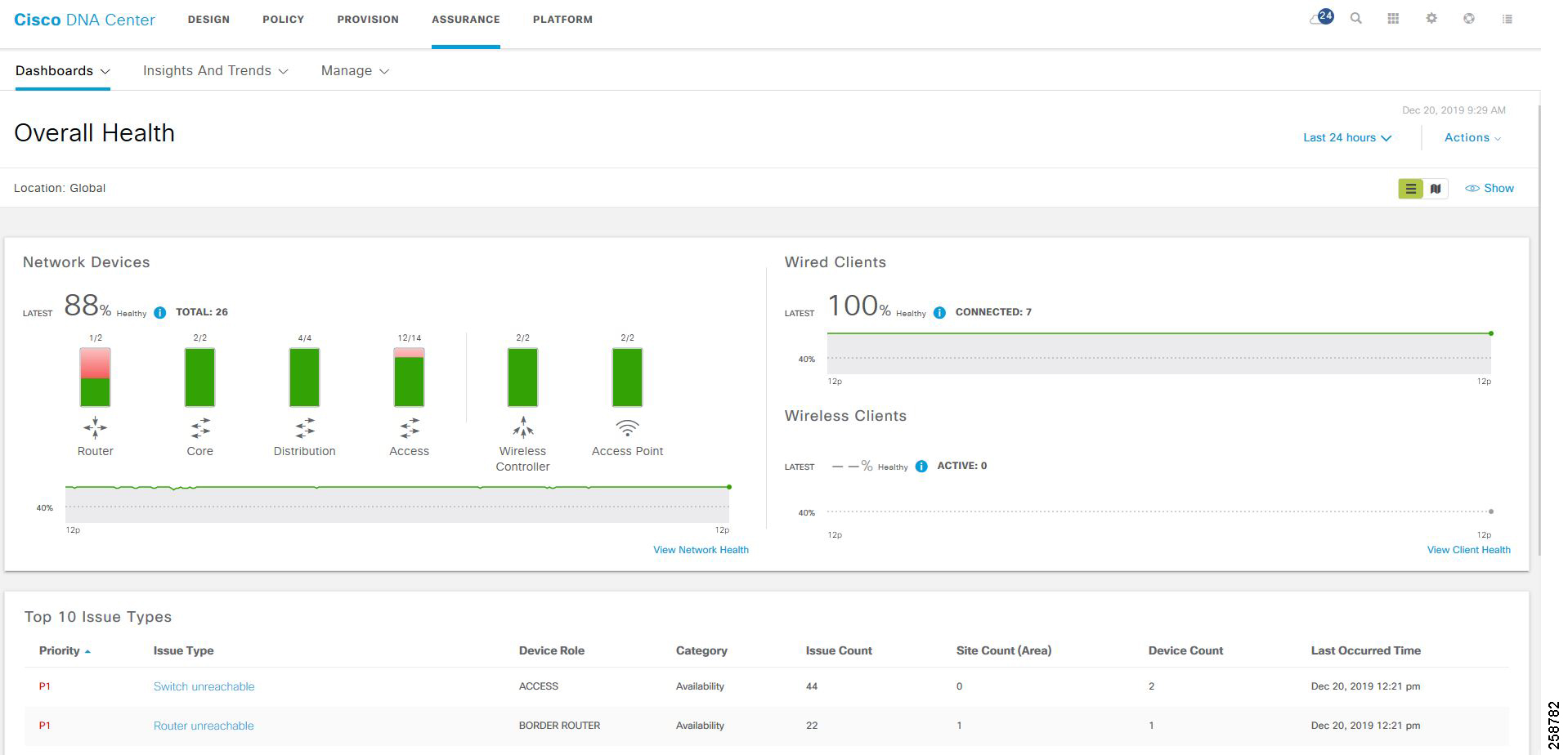
Network Health
View a summary of network health by clicking Health > Network on the Overall Health page or by clicking View Network Health at the bottom right of the Network Devices graph.
Near the top of the page, the network timeline is displayed. The slider bar can be adjusted to focus on a smaller slice of time. Using the Last 24 Hours drop-down list, up to 14 days of network health history are available.
In the Network Devices pane, devices are sorted by role and a summary of health score is indicated by color:
■![]() Red—Critical issues. Health score range is 1 to 3.
Red—Critical issues. Health score range is 1 to 3.
■![]() Orange—Warnings. Health score range is 4 to 7.
Orange—Warnings. Health score range is 4 to 7.
■![]() Green—No errors or warning. Health score range is 8 to 10.
Green—No errors or warning. Health score range is 8 to 10.
■![]() Gray—No data available. Health score is 0.
Gray—No data available. Health score is 0.
Like the Overall Health page, the Location pane can be toggled on or off by clicking Show. This pane lists devices and health status by site hierarchy, building, topology, or geographic views.
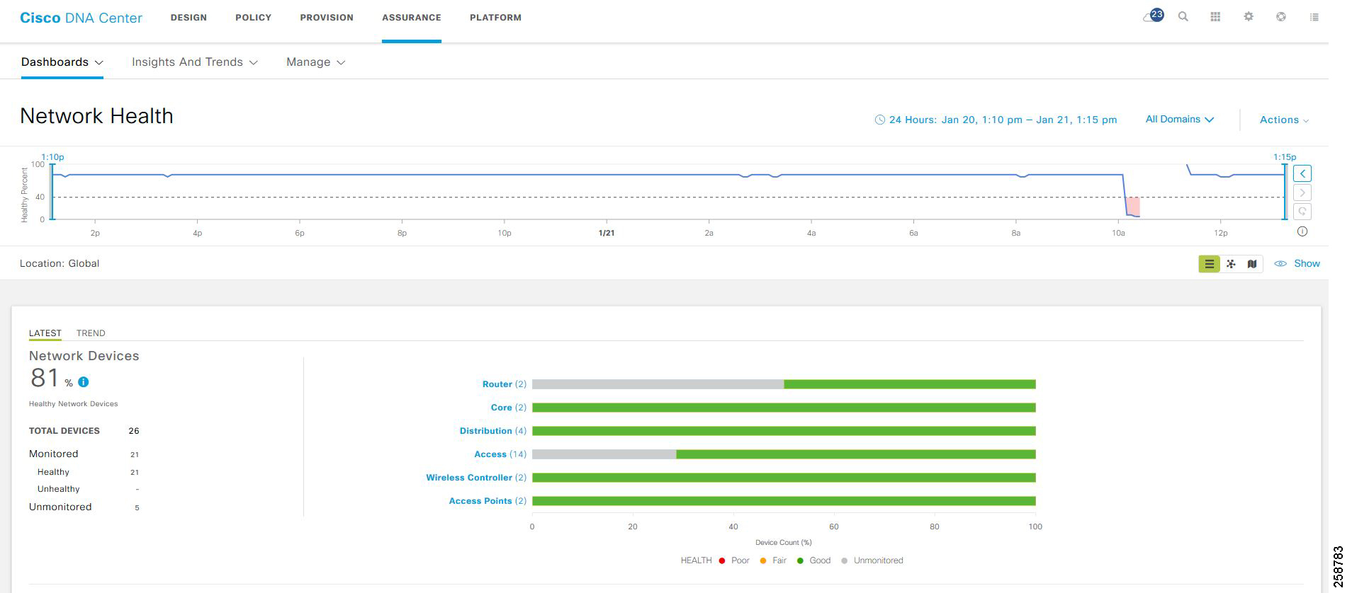
Further down the Network Health page, panes display wireless AP information. Following the AP metrics is a Network Devices pane that lists all devices used to determine the network health metric.
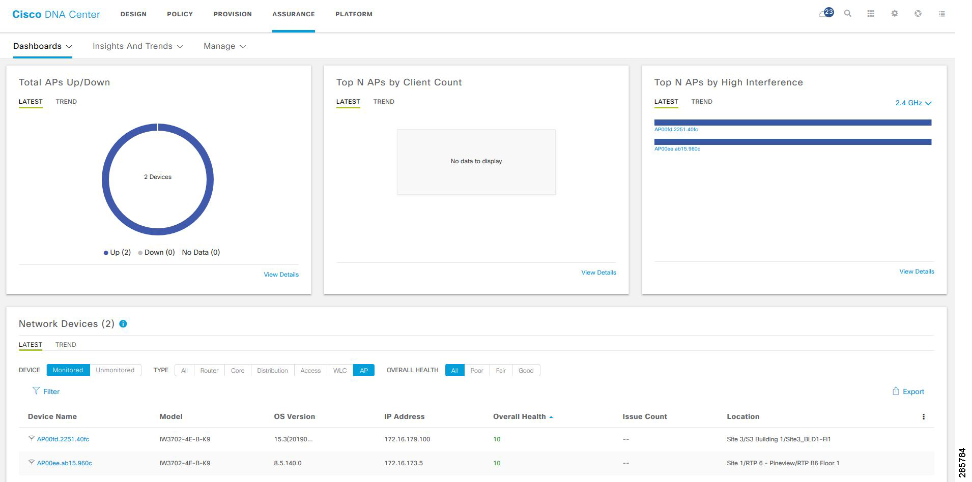
The list under Network Devices is filterable for quick identification of devices with outstanding issues. Hovering over the Overall Health Score for a given device will display the device health with health and percentage value of all KPI metrics. For more information about a device, click the device name to view complete information for the network device.
Device 360
The Device 360 page provides detailed information about a network device for troubleshooting issues.
At the top of the page, the Historical Health Graph displays device health over the specified time window. Click View Details in the upper right of the Device 360 window to view network information and rack location.
The Issues pane lists any issues detected by DNA that should be corrected. The most recent issue is listed first. Click an issue to view details. Any issue remains in the open state until the status is changed by clicking Status and selecting Ignore or Resolve.
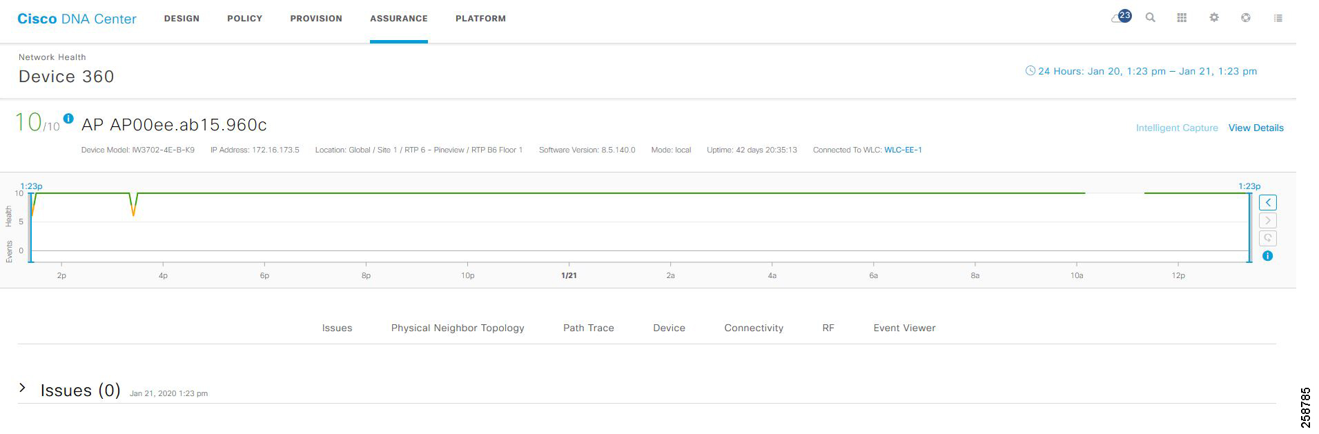
Following the Issues pane is the Physical Neighbor Topology pane. This shows connected devices and device and link health. Clicking a node brings up information about the target device. Hovering over a link displays details such as interface numbers, admin status, and mode.
Figure 37 Physical Network Topology
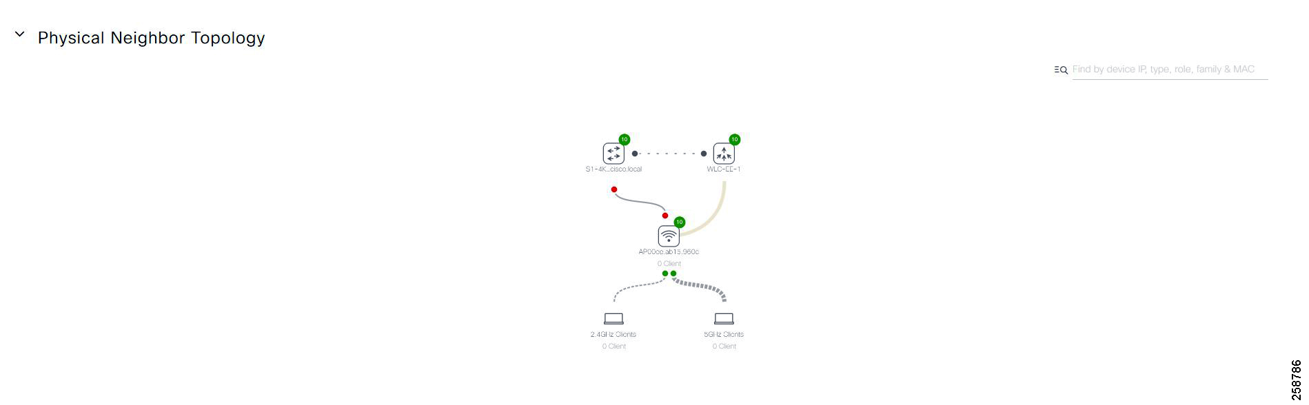
Following the Physical Neighbor Topology pane is the Event Viewer pane, which is for switches and routers, displays syslogs with a severity of an Error or above. Link status and device reachability events are recorded here. For APs, scenarios and sub-events are listed to help determine during which sub-event an issue occurred.
Warning: On the Device 360 page, you will find a Path Trace section. Path trace functionality is not described in this guide since in the Cisco DNA Center 1.3 release, this feature does not recognize extended nodes. Therefore, if a topology contains extended nodes, you may get an error message.
Client Health
View a summary of client health by clicking Health > Client on the Overall Health screen or by clicking View Client Health at the bottom right of the Wired and Wireless Clients graph.
The client timeline is displayed near the top of the page. In the Clients pane, devices are sorted as Wired or Wireless clients, and a summary of health score is indicated by color.
■![]() Red—Critical issues. Health score range is 1 to 3.
Red—Critical issues. Health score range is 1 to 3.
■![]() Orange—Warnings. Health score range is 4 to 7.
Orange—Warnings. Health score range is 4 to 7.
■![]() Green—No errors or warning. Health score range is 8 to 10.
Green—No errors or warning. Health score range is 8 to 10.
■![]() Gray—No data available. Health score is 0.
Gray—No data available. Health score is 0.
Like the Overall Health page, the Location pane can be toggled on or off by clicking Show. This pane lists client and health status by site hierarchy, building, topology, or geographic views.
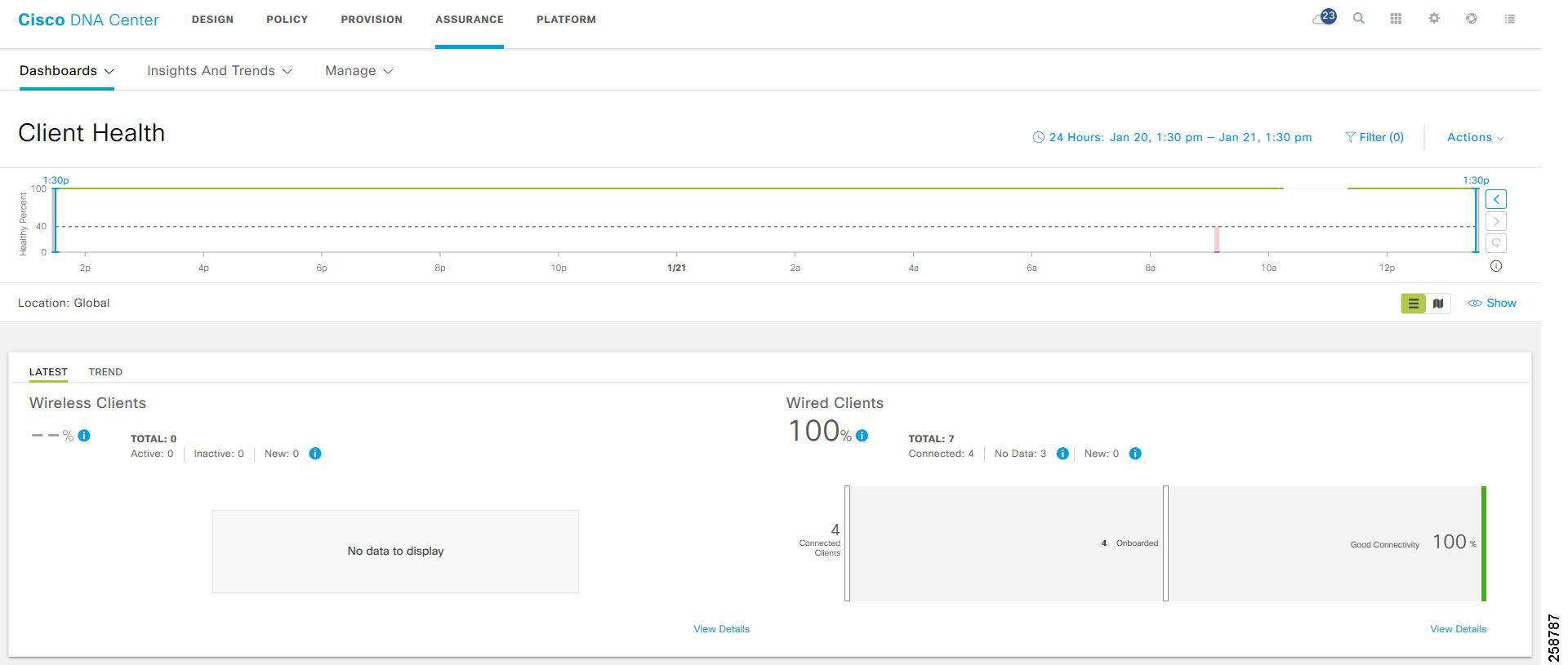
Further down the Client Health page, information is provided about Received Signal Strength Indication (RSSI), Signal-to-Noise Ratio (SNR), Roaming Times, Clients per SSID, Physical Link Connectivity, and Onboarding Times.
The Client Devices list is filterable for quick identification of clients with outstanding issues. The Client Health field displays the client health score, which is the average of its onboarding and connected scores. Health scores are calculated every five minutes. For more information about a client, click the client name to view Client 360 page for the device.
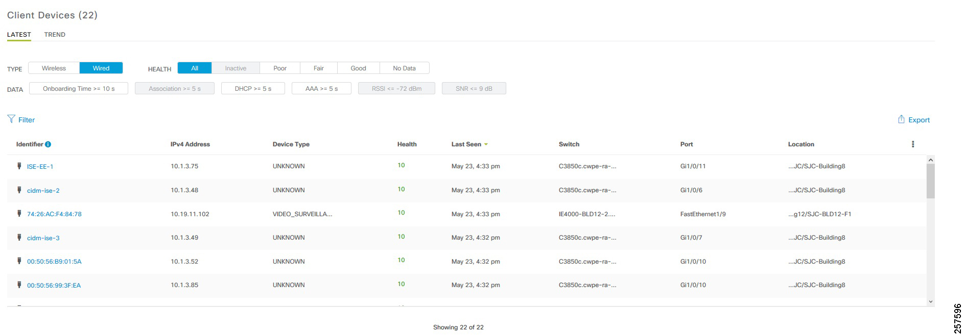
Client 360
Client 360 provides detailed information about a client for troubleshooting issues.
At the top of the page, the Historical Health Graph displays device health for the past 24 hours. Using the Last 24 Hours drop-down menu, this can be changed to 3 hours, 24 hours, or 7 days with a maximum history of 14 days.
The Issues pane lists any issues detected by the Cisco DNA Center that should be corrected. The most recent issue is listed first. Click an issue to view details. Any issue remains in the open state until status is changed by clicking Status and then selecting Ignore or Resolve.
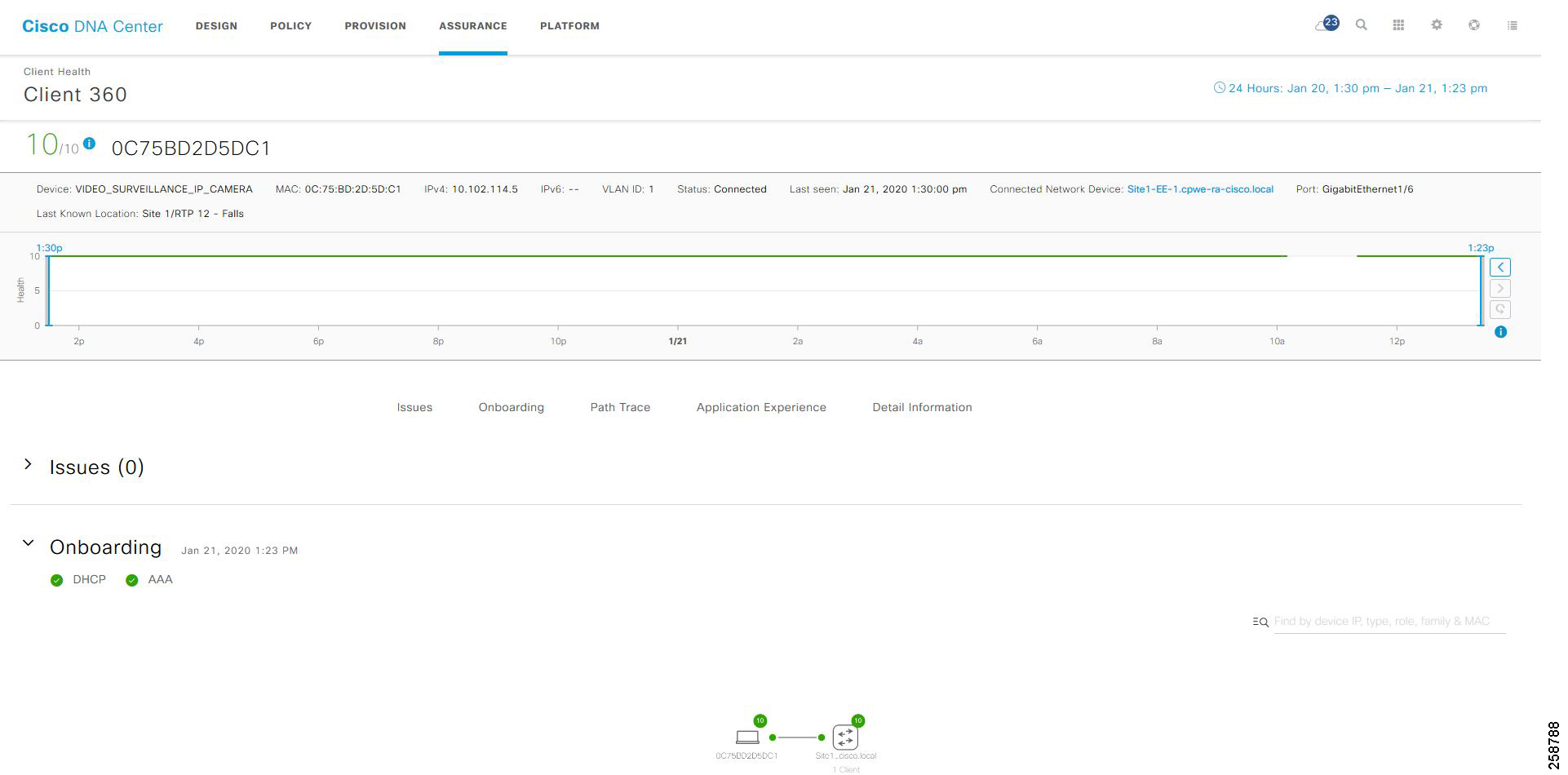
The Onboarding pane shows how the client connected to the network, information about onboarding services like DHCP and AAA, and device and link health. Clicking a node brings up information about the target device. Hovering over an endpoint displays details like interface numbers, admin status, and mode.
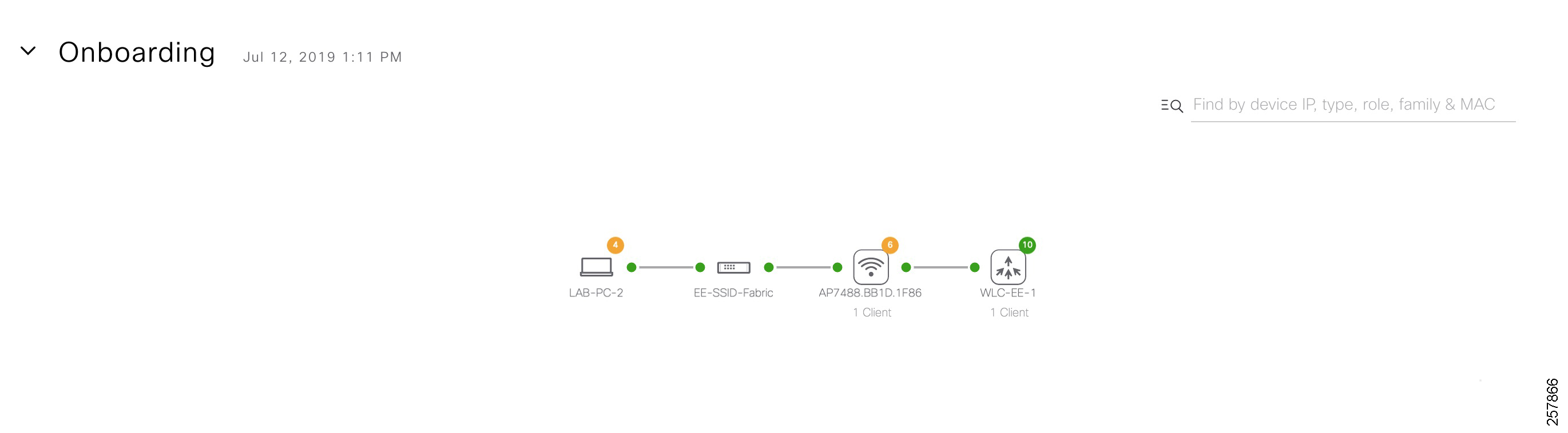
Issues
The Dashboards > Issues > Open displays a summary of all open network infrastructure with counters per issue, per site, and device count to help identify common or recurrent problems.
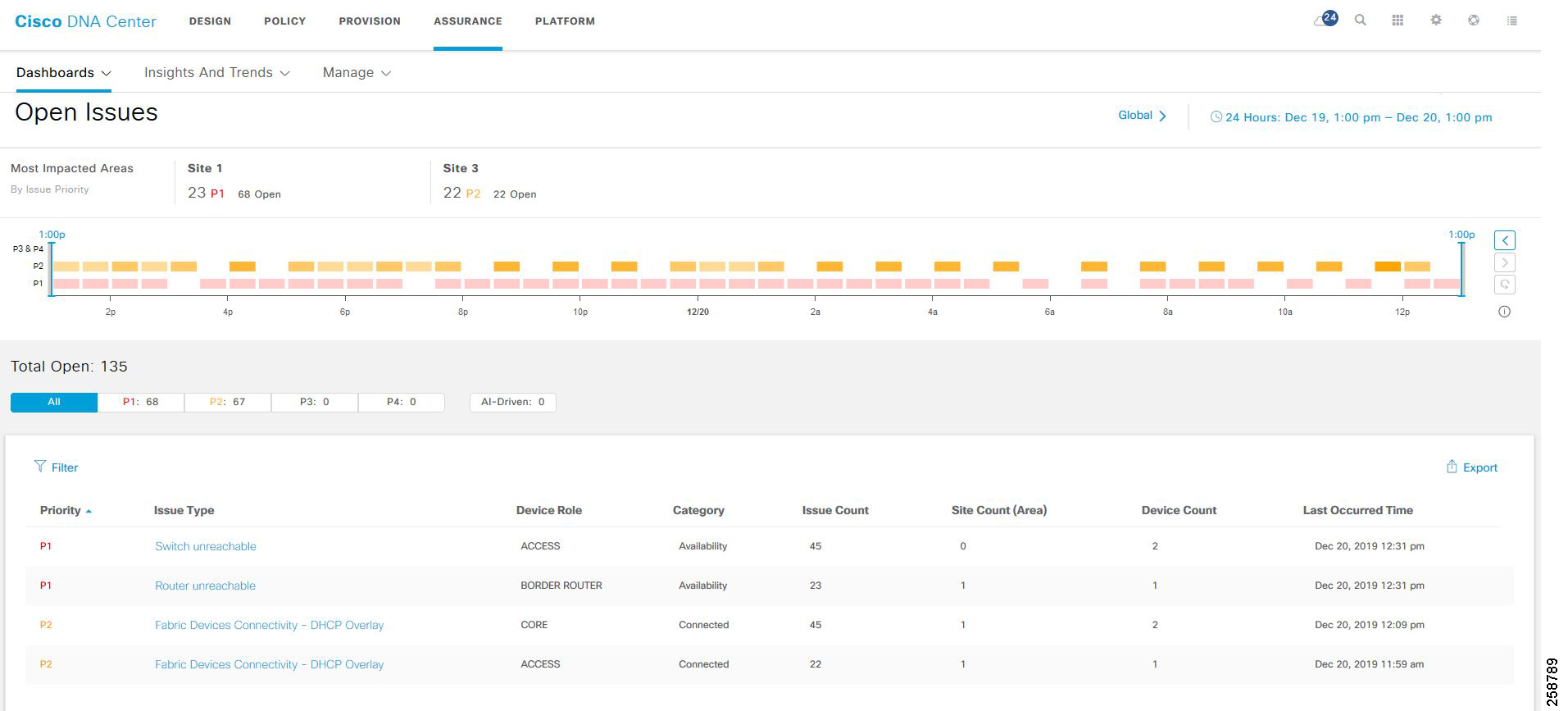
Appendix A Template Example
Example of template to configure NetFlow on 3400 switches.
Example of template to configure QoS Scheduling on 3400 switches.
The following diagram shows an example of a composite template that includes the NetFlow template and QoS template created above.
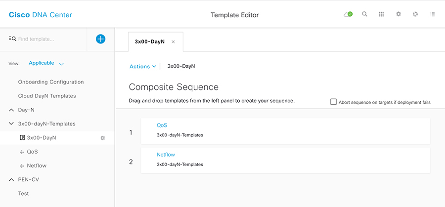
When applying the composite template, choose each template on the left panel to fill in the variables. Note the apply_template variable on top is used to control when a template is provisioned. If template needs to be pushed even if it was before, make sure to check the Push these templates even if its deployed before check box
Figure 44 Provisioning Composite Template
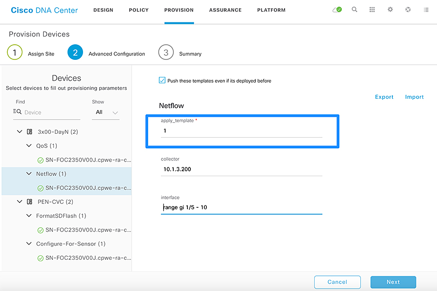
 Feedback