Installation, Maintenance, and Upgrade

Power Button Shutdown

The chassis runs in two modes:

  • Main power mode—Power is supplied to all chassis components and all operating systems can run.

  • Standby power mode—Power is supplied only to the service processor and certain components. You can safely remove power cords from the chassis in this mode.


Caution


After you shut down the chassis to standby power, electric current is still present in the chassis. To completely remove power as directed in some maintenance procedures, you must disconnect all power cords from all power supplies on the chassis.

You can shut down the chassis using the front panel Power button or software management. See the system shutdown procedure in the Cisco Secure Firewall Management Center Device Configuration Guide for your version for the software procedures.

Procedure


Step 1

Check the Power LED:

  • Amber—The chassis is already in standby mode and you can safely remove power.

  • Green—The chassis is in main power mode and you must shut it down before you can safely remove power.

Step 2

Perform a graceful shutdown or a hard shutdown:

Caution

 
To avoid data loss or damage to your operating system, perform a graceful shutdown of the operating system.
  • Graceful shutdown—Press and release the Power button. The operating system performs a graceful shutdown and the chassis goes into standby mode. The power LED is amber.

  • Emergency shutdown—Press and hold the Power button for four seconds to force the main power off and immediately enter standby mode.


Remove and Replace a Drive

The drives are hot-swappable. You do not have to shut down the chassis to remove or replace drives.


Caution


You cannot add more drives to the chassis. You can only replace the drives in the slots that are supported for your model. See Front Panel for the drive configurations.


Safety Warnings
Take note of the following warnings:

Warning


Statement 1028—More Than One Power Supply

This unit might have more than one power supply connection. To reduce risk of electric shock, remove all connections to de-energize the unit.


Warning


Statement 1073—No User-Serviceable Parts

There are no serviceable parts inside. To avoid risk of electric shock, do not open.


Warning


Statement 1089—Instructed and Skilled Person Definitions

An instructed person is someone who has been instructed and trained by a skilled person and takes the necessary precautions when working with equipment.

A skilled person or qualified personnel is someone who has training or experience in the equipment technology and understands potential hazards when working with equipment.

There are no serviceable parts inside. To avoid risk of electric shock, do not open.


Warning


Statement 1090—Installation by Skilled Person

Only a skilled person should be allowed to install, replace, or service this equipment. See statement 1089 for the definition of a skilled person.

There are no serviceable parts inside. To avoid risk of electric shock, do not open.


Warning


Statement 1091—Installation by an Instructed Person

Only an instructed person or skilled person should be allowed to install, replace, or service this equipment. See statement 1089 for the definition of an instructed or skilled person.

There are no serviceable parts inside. To avoid risk of electric shock, do not open.


Procedure


Step 1

Remove the drive that you are replacing:

  1. Press the release button on the face of the drive tray.

  2. Grasp and open the ejector handle and then pull the drive tray out of the slot.

    Figure 1. Remove the Drive

    1

    Ejector handle

    2

    Release button

Step 2

Remove the four drive-tray screws that secure the drive to the tray and then lift the drive out of the tray.

Figure 2. tttt
Figure 3. Remove the Drive Tray

1

Drive tray screws (two on each side)

2

Drive removed from drive tray

Step 3

Install a new drive:

  1. Place a new drive in the empty drive tray and install the four drive-tray screws.

  2. With the ejector handle on the drive tray open, insert the drive tray into the empty drive bay.

  3. Push the tray into the slot until it touches the backplane, and then close the ejector handle to lock the drive in place.


Remove and Replace a Power Supply

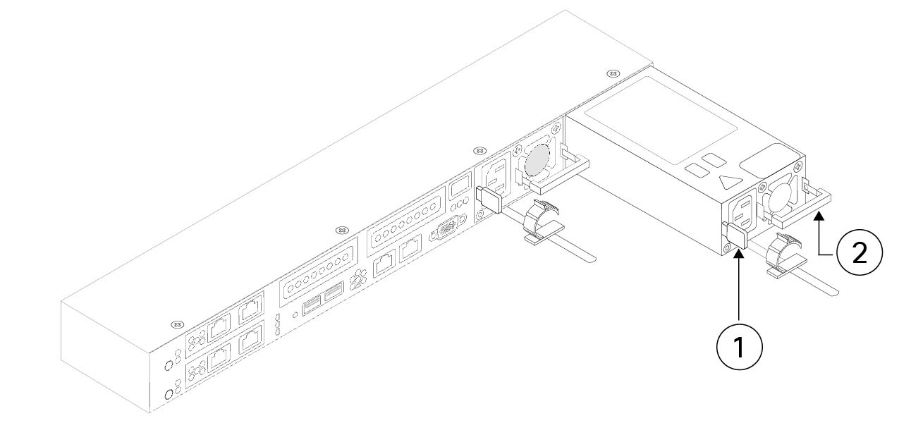
The chassis ships with two power supplies, which are redundant and hot-swappable. One is the active power supply and the other is the standby power supply (1+1).

This chassis also supports cold redundancy. Depending on the power being drawn by the chassis, one power supply might actively provide all power to the system while the remaining power supply is put into a standby state. For example, if the power consumption can be satisfied by power supply 1, then power supply 2 is put into a standby state.


Caution


When you replace power supplies, do not mix power supply types in the chassis. Both power supplies must be the same wattage and Cisco PID.


Trouble


Power supply health monitoring notifies you if the power supply loses power or malfunctions so that redundancy is lost. Check the power supply cables to make sure they are functioning. If they are and errors are still occurring, replace the power supply.


Safety Warnings
Take note of the following warnings:

Warning


Statement 1005—Circuit Breaker

This product relies on the building’s installation for short-circuit (overcurrent) protection. Ensure that the protective device is rated not greater than: AC 20 A/DC 40 A


Warning


Statement 1017—Restricted Area

This unit is intended for installation in restricted access areas. Only skilled, instructed, or qualified personnel can access a restricted access area.


Warning


Statement 1022—Disconnect Device

To reduce the risk of electric shock and fire, a readily accessible disconnect device must be incorporated in the fixed wiring.


Warning


Statement 1028—More Than One Power Supply

This unit might have more than one power supply connection. To reduce risk of electric shock, remove all connections to de-energize the unit.


Warning


Statement 1029—Blank Faceplates and Cover Panels

Blank faceplates and cover panels serve three important functions: they reduce the risk of electric shock and fire, they contain electromagnetic interference (EMI) that might disrupt other equipment, and they direct the flow of cooling air through the chassis. Do not operate the system unless all cards, faceplates, front covers, and rear covers are in place.


Warning


Statement 1046—Installing or Replacing the Unit

To reduce risk of electric shock, when installing or replacing the unit, the ground connection must always be made first and disconnected last.

If your unit has modules, secure them with the provided screws.


Warning


Statement 1073—No User-Serviceable Parts

There are no serviceable parts inside. To avoid risk of electric shock, do not open.


Warning


Statement 1089—Instructed and Skilled Person Definitions

An instructed person is someone who has been instructed and trained by a skilled person and takes the necessary precautions when working with equipment.

A skilled person or qualified personnel is someone who has training or experience in the equipment technology and understands potential hazards when working with equipment.

There are no serviceable parts inside. To avoid risk of electric shock, do not open.


Warning


Statement 1090—Installation by Skilled Person

Only a skilled person should be allowed to install, replace, or service this equipment. See statement 1089 for the definition of a skilled person.

There are no serviceable parts inside. To avoid risk of electric shock, do not open.


Warning


Statement 1091—Installation by an Instructed Person

Only an instructed person or skilled person should be allowed to install, replace, or service this equipment. See statement 1089 for the definition of an instructed or skilled person.

There are no serviceable parts inside. To avoid risk of electric shock, do not open.


Procedure


Step 1

Remove the power supply:

  1. Grasp the power supply handle while pinching the release lever toward the handle.

  2. Pull the power supply out of the bay.

Figure 4. Remove and Replace the AC Power Supply

1

Release lever

2

Handle

Step 2

Install a new power supply:

  1. Grasp the power supply handle and insert the new power supply into the empty bay.

  2. Push the power supply into the bay until the release lever locks.

  3. Connect the power cord to the new power supply.

  4. If you shut down the chassis, press the Power button to return it to main power mode.