- About This Guide
- About the Firepower 8000 Series
- Hardware Specifications
- Installing a Firepower 8000 Series Device
- Using the LCD Panel on a Firepower Device
- Deploying on a Management Network
- Deploying Firepower Managed Devices
- Power Requirements for Firepower 8000 Series Devices
- Inserting and Removing Firepower 8000 Series Modules
- Installing a Malware Storage Pack
- Rack and Cabinet Mounting Options
- Firepower 8000 Series Devices
- Firepower 8000 Series Chassis Front View
- Firepower 8000 Series Chassis Rear View
- Firepower 8000 Series Physical and Environmental Parameters
- Firepower 8000 Series Modules
- QuadPort 1000BASET Copper Configurable Bypass NetMod
- QuadPort 1000BASESX Fiber Configurable Bypass NetMod
- DualPort 10GBASE (MMSR or SMLR) Fiber Configurable Bypass NetMod
- DualPort 40GBASE-SR4 Fiber Configurable Bypass NetMod
- QuadPort 1000BASE-T Copper NonBypass NetMod
- QuadPort 1000BASE-SX Fiber NonBypass NetMod
- QuadPort 10GBASE (MMSR or SMLR) Fiber NonBypass NetMod
- Stacking Module
Hardware Specifications
Firepower 8000 Series devices are delivered on a variety of platforms to meet the needs of your organization.
Rack and Cabinet Mounting Options
You can mount Firepower devices in racks and server cabinets. The appliance comes with a rack-mounting kit. For information on mounting the appliance in a rack, refer to the instructions delivered with the rack-mounting kit.
Firepower 8000 Series Devices
The Firepower 8000 Series devices use network modules (NetMods) that contain either copper or fiber sensing interfaces. The devices can be shipped fully assembled or you can install the modules. Assemble your device before installing the Firepower System. See the assembly instructions shipped with your modules.
Some 8000 Series devices can be stacked to increase the capability of the system. For each stacking kit, you replace a NetMod with a stacking module and cable the devices together using the 8000 Series stacking cable. See Using Devices in a Stacked Configuration for more information.
The Firepower 8000 Series device can be delivered on a variety of chassis:
- AMP8050 is a 1U chassis and can contain up to three modules.
- Firepower 8120, 8130, 8140, and AMP8150, also known as the 81xx Family, is a 1U chassis and can contain up to three modules. For the Firepower 8140 only, you can add a stacking kit for a total 2U configuration.
- Firepower 8250, part of the 82xx Family, is a 2U chassis and can contain up to seven modules. You can add up to three stacking kits for a total 8U configuration.
- Firepower 8260, part of the 82xx Family, is a 4U configuration with two 2U chassis. The primary chassis contains one stacking module and up to six sensing modules. The secondary chassis contains one stacking module. You can add up to two stacking kits for a total 8U configuration.
- Firepower 8270, part of the 82xx Family, is a 6U configuration with three 2U chassis. The primary chassis contains two stacking modules and up to five sensing modules. Each secondary chassis contains one stacking module. You can add one stacking kit for a total 8U configuration.
- Firepower 8290, part of the 82xx Family, is an 8U configuration with four 2U chassis. The primary chassis contains three stacking modules and up to four sensing modules. Each secondary chassis contains one stacking module. This model is fully configured and does not accept a stacking kit.
- Firepower 8350 and AMP8350, part of the 83xx Family, is a 2U chassis and can contain up to seven modules. You can add up to three stacking kits for a total 8U configuration.
- Firepower 8360 and AMP8360, part of the 83xx Family, is a 4U configuration with two 2U chassis. The primary chassis contains one stacking module and up to six sensing modules. The secondary chassis contains one stacking module. You can add up to two stacking kits for a total 8U configuration.
- Firepower 8370 and AMP8370, part of the 83xx Family, is a 6U configuration with three 2U chassis. The primary chassis contains two stacking modules and up to five sensing modules. Each secondary chassis contains one stacking module. You can add one stacking kit for a total 8U configuration.
- Firepower 8390 and AMP8390, part of the 83xx Family, is an 8U configuration with four 2U chassis. The primary chassis contains three stacking modules and up to four sensing modules. Each secondary chassis contains one stacking module. This model is fully configured and does not accept a stacking kit.

Note![]() The AMP models have many of the same form factors as their Firepower counterparts, but have been optimized to take advantage of the Firepower System’s network-based advanced malware protection (AMP) capabilities.
The AMP models have many of the same form factors as their Firepower counterparts, but have been optimized to take advantage of the Firepower System’s network-based advanced malware protection (AMP) capabilities.
See the following sections for more information:
- Firepower 8000 Series Chassis Front View
- Firepower 8000 Series Chassis Rear View
- Firepower 8000 Series Physical and Environmental Parameters
- Firepower 8000 Series Modules
Firepower 8000 Series Chassis Front View
The Firepower 8000 Series chassis can be in the AMP8x50, 81xx Family, the 82xx Family, or the 83xx Family. See the Regulatory Compliance and Safety Information for FirePOWER and FireSIGHT Appliances document for safety considerations for AMP8x50, 81xx Family, 82xx Family, and 83xx Family appliances.
AMP8x50 and Firepower 81xx Family Chassis Front View
The front view of the chassis contains the solid-state disk drive, LCD panel, front panel, and three module slots.
Figure 2-1 AMP8x50 and Firepower 81xx Family (Chassis: CHAS-1U-AC/DC) Front View

Firepower 82xx Family and Firepower and AMP 83xx Family Chassis Front View
The front view of the chassis contains the LCD panel, front panel, and seven module slots.
Figure 2-2 Firepower 82xx Family (Chassis: CHAS-2U-AC/DC) and Firepower and AMP 83xx Family (PG35-2U-AC/DC) Front View

The following table describes the features on the front of the appliance.
|
|
|
|---|---|
Houses a solid-state drive (SSD) that functions as the primary system drive used for the operating system, the Firepower System software, and local file storage of events and configuration files. See Installing a Malware Storage Pack for information about installing an optional second SSD for expanded local file storage of suspected malware. |
|
Contain the modules. For information on available modules, see Firepower 8000 Series Modules. |
|
Operates in multiple modes to configure the device, display error messages, and view system status. For more information, see Using the LCD Panel on a Firepower Device. |
|
Houses LEDs that display the system’s operating state, as well as various controls, such as the power button. For more information, see Firepower 82xx Family and Firepower and AMP 83xx Family Front Panel. |
|
The USB 2.0 port allows you to attach a keyboard to the device. |
Firepower 8000 Series Front Panel
The front panel for the Firepower and AMP 81xx Family, 82xx Family, and 83xx Family contain the same components.
Figure 2-3 Firepower 81xx Family Front Panel

Figure 2-4 Firepower 82xx Family and Firepower and AMP 83xx Family Front Panel

The front panel of the chassis houses LEDs, which display the system’s operating state. The following table describes the LEDs on the front panel
|
|
|
|---|---|
Note The amber status light takes precedence over the green status light. When the amber light is on or blinking, the green light is off. See Table 2-4 for more information. |
|
Helps identify a system installed in a high-density rack with other similar systems: |
|
The following table describes the conditions under which the system status LEDs might be lit.
Firepower 8000 Series Chassis Rear View
The Firepower 8000 Series chassis can be in the 81xx Family, 82xx Family, or 83xx Family.
AMP8x50 and Firepower 81xx Family Chassis Rear View
The rear of the chassis contains connection ports, the management interface, and the power supplies.
Figure 2-5 AMP8x50 and Firepower 81xx Family (Chassis: CHAS-1U-AC/DC) Rear View

Firepower 82xx Family Chassis Rear View
The rear of the chassis contains power supplies, solid-state disk drives, connection ports, and the management interface.
Figure 2-6 Firepower 82xx Family (Chassis: CHAS-2U-AC/DC) Rear View

Firepower and AMP 83xx Family Chassis Rear View
The rear of the chassis contains power supplies, solid-state disk drives, connection ports, and the management interface.
Figure 2-7 Firepower and AMP 83xx Family (Chassis: PG35-2U-AC/DC) Rear View

The following table describes the features that appear on the rear of the appliance.

Note![]() The Firepower 83xx Family hardware platform has six fans that display as FAN2 through FAN7. This is expected behavior. There is no FAN1 on the 83xx Family platform.
The Firepower 83xx Family hardware platform has six fans that display as FAN2 through FAN7. This is expected behavior. There is no FAN1 on the 83xx Family platform.
|
|
|
|---|---|
Allows you to attach a monitor, keyboard, and mouse to the device, as an alternative to using the serial port, to establish a direct workstation-to-appliance connection. |
|
Allows you to establish a direct workstation-to-appliance connection (using an RJ45 to DB-9 adapter) for direct access to all of the management services on the device. The RJ45 serial port is used for maintenance and configuration purposes only and is not intended to carry service traffic. |
|
Allows you to establish a direct workstation-to-appliance connection for direct access to all of the management services on the device. The RJ232 serial port is used for maintenance and configuration purposes only and is not intended to carry service traffic. |
|
Provides for an out-of-band management network connection. The management interface is used for maintenance and configuration purposes only and is not intended to carry service traffic. |
|
Provides power to the device through an AC power source. Looking at the rear of the chassis, power supply #1 is on the right and power supply #2 is on the left. |
|
Houses a solid-state drive (SSD) that functions as the primary system drive used for the operating system, the Firepower System software, and local file storage of events and configuration files. |
|
Allows you to connect the appliance to the Common Bonding Network. See the Power Requirements for Firepower 8000 Series Devices for more information. |
The 10/100/1000 management interface is located on the rear of the appliance. The following table describes the LEDs associated with the management interface.
|
|
|
|---|---|
The power supply modules are located on the rear of the appliance. The following table describes the LEDs associated with the management interface.
The following table lists the signals on a typical DB-9 serial connector and the corresponding pins on the device’s RJ45 serial connectors. You can use this table to construct an adapter for serial connections.
|
|
|
|
|
|---|---|---|---|
Firepower 8000 Series Physical and Environmental Parameters
The following table describes the physical attributes and environmental parameters for AMP8x50 and 81xx Family devices.
|
|
|
|---|---|
Quad-port Gigabit copper Ethernet configurable bypass interfaces in a paired configuration |
|
Dual-port fiber configurable bypass interfaces with LC connectors |
|
Quad-port fiber configurable bypass interfaces 1000BASE-SX with LC connectors |
|
Quad-port Gigabit copper Ethernet non-bypass interfaces in a paired configuration |
|
Quad-port fiber non-bypass interfaces with LC connectors |
|
Quad-port fiber non-bypass interfaces 1000BASE-SX with LC connectors |
|
Dual 650 W redundant power supplies designed for AC or DC. AC Voltage: 100 VAC to 240 VAC nominal (85 VAC to 264 VAC maximum) DC Voltage: -48 VDC nominal referenced to RTN |
|
| See Installing a Malware Storage Pack for information about installing an optional second SSD for expanded local file storage of suspected malware. |
|
5% to 90%, non-condensing with a maximum wet bulb of 82 o F (28 o C) at temperatures from 77°F to 95°F (25°C to 35°C) |
|
| You must provide sufficient cooling to maintain the appliance within its required operating temperature range. Failure to do this may cause a malfunction or damage to the appliance. |
|
Max normal operating noise is 87.6 dB LWAd (high temperature). |
|
No errors with half a sine wave shock of 2G (with 11 ms duration) |
|
| Restriction of the airflow such as blocking the front or back or enclosing the unit in a cabinet without sufficient clearance may cause the unit to overheat, even if the ambient temperature is in the operating range. Airflow through the appliance enters at the front and exits at the rear. The minimum recommended clearance in the front and back is 7.9 in. |
The following table describes the physical attributes and environmental parameters for Firepower 82xx Family and the Firepower and AMP 83xx Family devices.
|
|
|
|
|---|---|---|
| 29.0 in. x 17.2 in. x 3.48 in. (73.5 cm x 43.3 cm x 88.2 cm) |
||
| Quad-port Gigabit copper Ethernet configurable bypass interfaces in a paired configuration |
||
| Dual-port fiber configurable bypass interfaces with LC connectors |
||
| Quad-port fiber configurable bypass interfaces1000BASE-SX with LC connectors |
||
| Dual-port fiber configurable bypass interfaces with OTP/MTP connectors |
||
| Quad-port Gigabit copper Ethernet non-bypass interfaces in a paired configuration |
||
| Quad-port fiber non-bypass interfaces with LC connectors |
||
| Quad-port fiber non-bypass interfaces 1000BASE-SX with LC connectors |
||
Dual 750 W redundant power supplies designed for AC or DC. AC Voltage: 100 VAC to 240 VAC nominal (85 VAC to 264 VAC DC Voltage: -48 VDC nominal referenced to RTN |
||
Dual 1000 W redundant power supplies designed for AC or DC. AC Voltage: 100 VAC to 240 VAC nominal (85 VAC to 264 VAC DC Voltage: -48 VDC nominal referenced to RTN |
||
| See Installing a Malware Storage Pack for information about installing an optional second SSD for expanded local file storage of suspected malware. |
||
| 5% to 90%, non-condensing with a maximum wet bulb of 82°F (28°C) at temperatures from 77°F to 95°F (25°C to 35°C) |
||
| You must provide sufficient cooling to maintain the appliance within its required operating temperature range. Failure to do this may cause a malfunction or damage to the appliance. |
||
| Max normal operating noise is 81.6 dB LWAd (high temperature). |
||
| No errors with half a sine wave shock of 2G (with 11 ms duration) |
||
| Front to back, 210 ft 3 (6 m 3) per minute Restriction of the airflow such as blocking the front or back or enclosing the unit in a cabinet without sufficient clearance may cause the unit to overheat, even if the ambient temperature is in the operating range. Airflow through the appliance enters at the front and exits at the rear. The minimum recommended clearance in the front and back is 7.9 in. (20cm). This minimum can only be used if you can ensure a supply of low temperature air at the front of the appliance. |
||
Firepower 8000 Series Modules
The sensing interfaces for the Firepower 8000 Series appliances can be delivered with copper or fiber interfaces.

The following modules contain configurable bypass sensing interfaces:
- a quad-port 1000BASE-T copper interface with configurable bypass capability. See Quad-Port 1000BASE-T Copper Configurable Bypass NetMod.
- a quad-port 1000BASE-SX fiber interface with configurable bypass capability. See Quad-Port 1000BASE-SX Fiber Configurable Bypass NetMod for more information.
- a dual-port 10GBASE (MMSR or SMLR) fiber interface with configurable bypass capability. See Dual-Port 10GBASE (MMSR or SMLR) Fiber Configurable Bypass NetMod for more information.
- a dual-port 40GBASE-SR4 fiber interface with configurable bypass capability (2U devices only). See Dual-Port 40GBASE-SR4 Fiber Configurable Bypass NetMod for more information.
The following modules contain non-bypass sensing interfaces:
- a quad-port 1000BASE-T copper interface without bypass capability. See Quad-Port 1000BASE-T Copper Non-Bypass NetMod for more information.
- a quad-port 1000BASE-SX fiber interface without bypass capability. See Quad-Port 1000BASE-SX Fiber Non-Bypass NetMod for more information.
- a quad-port 10GBASE (MMSR or SMLR) fiber interface without bypass capability. See Quad-Port 10GBASE (MMSR or SMLR) Fiber Non-Bypass NetMod for more information.
In addition, you can use a stacking module to connect two Firepower 8140, up to four Firepower 8250, or up to four Firepower or AMP 8350 devices to combine their processing power and increase throughput. See Stacking Module for more information.
Quad-Port 1000BASE-T Copper Configurable Bypass NetMod
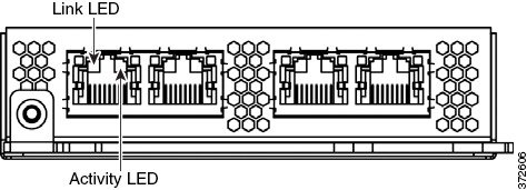
The quad-port 1000BASE-T copper configurable bypass NetMod contains four copper ports and link, activity, and bypass LEDs.

Use the following table to understand the link and activity LEDs on copper interfaces.
|
|
|
|---|---|
Use the following table to understand the bypass LEDs on copper interfaces.
|
|
|
|---|---|
The interface is in bypass mode; that is, it has failed open. |
Quad-Port 1000BASE-SX Fiber Configurable Bypass NetMod
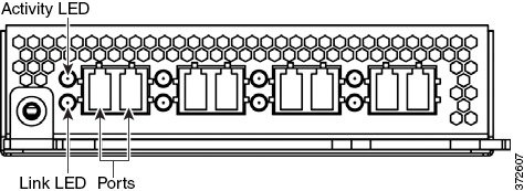
The quad-port 1000BASE-SX fiber configurable bypass NetMod contains four fiber ports and link, activity, and bypass LEDs.

Use the following table to understand link and activity LEDs of the fiber interfaces.
|
|
|
|---|---|
Use the following table to understand bypass LEDs on the fiber interfaces.
|
|
|
|---|---|
The interface is in bypass mode; that is, it has failed open. |
Use the following table to understand the optical specifications of the fiber interfaces.
|
|
|
|---|---|
Dual-Port 10GBASE (MMSR or SMLR) Fiber Configurable Bypass NetMod
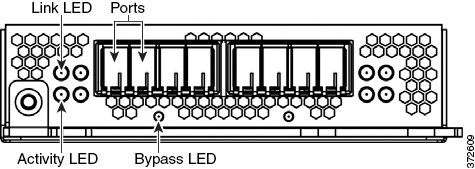
The dual-port 10GBASE (MMSR or SMLR) fiber configurable bypass NetMod contains two fiber ports and link, activity, and bypass LEDs.

Use the following table to understand link and activity LEDs of the fiber interfaces.
|
|
|
|---|---|
Use the following tables to understand the bypass LEDs on the fiber interfaces.
|
|
|
|---|---|
The interface is in bypass mode; that is, it has failed open. |
Use the following table to understand the optical parameters of the fiber interfaces.
Dual-Port 40GBASE-SR4 Fiber Configurable Bypass NetMod
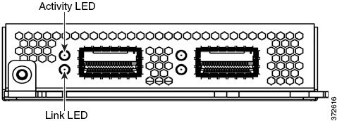
The dual-port 40GBASE-SR4 fiber configurable bypass NetMod contains two fiber ports and link, activity, and bypass LEDs.

You can use the 40G NetMod in the following 8000 Series models:
- Firepower 8270 and 8290
- Firepower and AMP 8360, 8370 and 8390
- Firepower 8250 and 8260 (must be 40G-capable)
- Firepower and AMP 8350 (must be 40G-capable)

Use the following table to understand link and activity LEDs of the fiber interfaces.
|
|
|
|---|---|
The light flashes when the interface has activity. If dark, there is no activity. |
|
The light is on when the interface has link. If dark, there is no link. |
Use the following table to understand bypass LED of the fiber interfaces.
|
|
|
|---|---|
The interface pair does not have link and is not in bypass mode, or has no power. |
|
The interface is in bypass mode; that is, it has failed open. |
Use the following table to understand optical parameters of the fiber interfaces.
Quad-Port 1000BASE-T Copper Non-Bypass NetMod
The quad-port 1000BASE-T copper non-bypass NetMod contains four copper ports, and link and activity LEDs.

Use the following table to understand copper LEDs.
|
|
|
|---|---|
Quad-Port 1000BASE-SX Fiber Non-Bypass NetMod
The quad-port 1000BASE-SX fiber non-bypass NetMod contains four fiber ports, and link and activity LEDs.

Use the following table to understand the link and activity LEDs on the fiber interfaces.
Use the following table to understand the optical parameters of the fiber interfaces.
|
|
|
|---|---|
Quad-Port 10GBASE (MMSR or SMLR) Fiber Non-Bypass NetMod
The quad-port 10GBASE (MMSR or SMLR) fiber non-bypass NetMod contains four fiber ports, and link and activity LEDs.


Use the following table to understand the link and activity LEDs on fiber interfaces.
Use the following table to understand the optical parameters of the fiber interfaces.
Stacking Module
The stacking module contains two connection ports for the 8000 Series stacking cable, and activity and link LEDs.

You can use the stacking module optionally in the following 8000 Series models:
The stacking module is included in the following 8000 Series stacked configurations:
You can use the following table to understand the stacking LEDs.
|
|
|
|---|---|
 Feedback