About Threat Defense Interfaces
Threat Defense includes data interfaces as well as a Management interface.
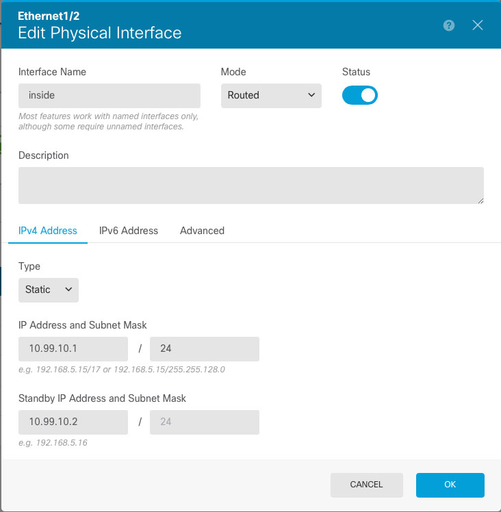
When you attach a cable to an interface connection (physically or virtually), you need to configure the interface. At minimum, you need to name the interface and enable it for it to pass traffic. If the interface is a member of a bridge group, this is sufficient. For non-bridge group members, you also need to give the interface an IP address. If you intend to create VLAN subinterfaces rather than a single physical interface on a given port, you would typically configure the IP addresses on the subinterface, not on the physical interface. VLAN subinterfaces let you divide a physical interface into multiple logical interfaces that are tagged with different VLAN IDs, which is useful when you connect to a trunk port on a switch. You do not configure IP addresses on passive interfaces.
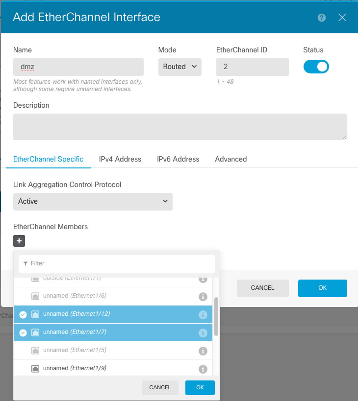
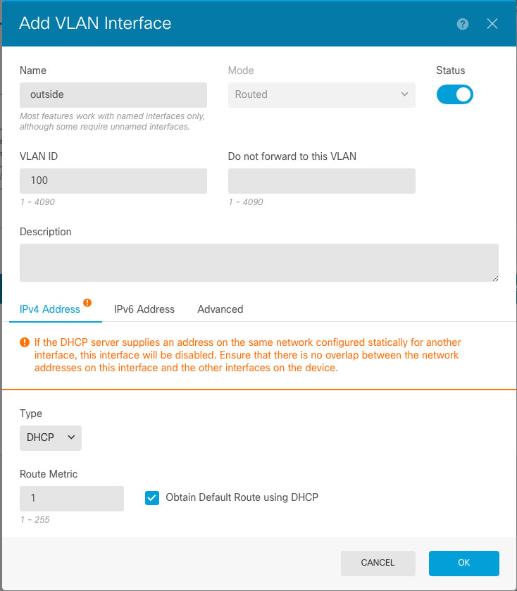
The Interfaces page include sub-pages for interface types: Interfaces (for physical interfaces), Bridge Groups, Virtual Tunnel Interfaces, EtherChannels, and VLANs (for the Firepower 1010 and Secure Firewall 1210/1220). Note that Firepower 4100/9300 EtherChannels are listed on the Interfaces page and not on the EtherChannel page, because you can only modify EtherChannel parameters in FXOS, not in the device manager. Each page shows the available interfaces, their names, addresses, modes, and states. You can change the state of an interface, on or off, directly in the list of interfaces. The list shows the interface characteristics based on your configuration. Use the open/close arrow on a bridge group, EtherChannel, or VLAN interface to view the member interfaces, which also appear by themselves in the appropriate list. You can also view subinterfaces for supported parent interfaces. For information on how these interfaces map to virtual interfaces and network adapters, see How VMware Network Adapters and Interfaces Map to the Threat Defense Physical Interfaces.
The following topics explain the limitations of configuring interfaces through the device manager as well as other interface management concepts.
Interface Modes
You can configure one of the following modes for each interface:
- Routed
-
Each Layer 3 routed interface requires an IP address on a unique subnet. You would typically attach these interfaces to switches, a port on another router, or to an ISP/WAN gateway.
- Inline
-
After you add an interface to an inline set, the mode is changed to Inline. You cannot directly select Inline as the mode.
- Passive
-
Passive interfaces monitor traffic flowing across a network using a switch SPAN (Switched Port Analyzer) or mirror port. The SPAN or mirror port allows for traffic to be copied from other ports on the switch. This function provides the system visibility within the network without being in the flow of network traffic. When configured in a passive deployment, the system cannot take certain actions such as blocking or shaping traffic. Passive interfaces receive all traffic unconditionally and no traffic received on these interfaces is retransmitted.
- Switch Port (Firepower 1010 and Secure Firewall 1210/1220)
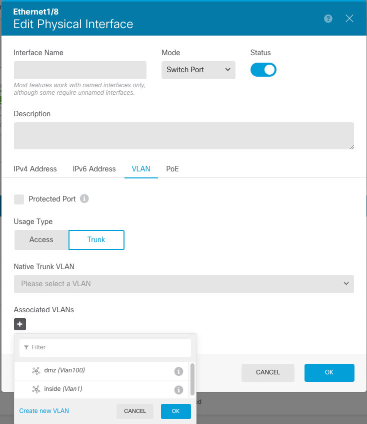
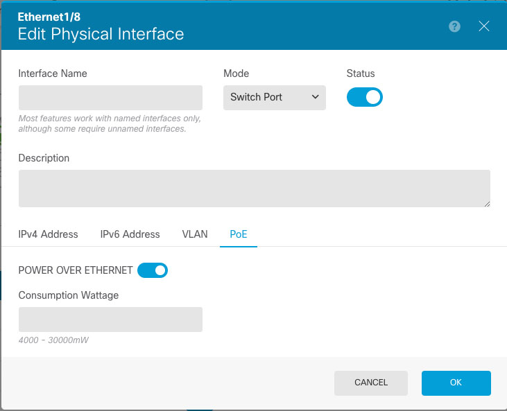
- Switch ports forward traffic at Layer 2, using the switching function in hardware. Switch ports on the same VLAN can communicate with each other using hardware switching, and traffic is not subject to the threat defense security policy. Access ports accept only untagged traffic, and you can assign them to a single VLAN. Trunk ports accept untagged and tagged traffic, and can belong to more than one VLAN. You cannot configure the Management interface as a switch port.
- BridgeGroupMember
-
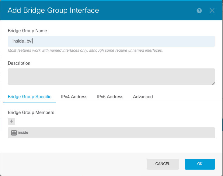
A bridge group is a group of interfaces that the threat defense device bridges instead of routes. All interfaces are on the same network. The bridge group is represented by a Bridge Virtual Interface (BVI) that has an IP address on the bridge network.
You can route between routed interfaces and BVIs, if you name the BVI. In this case, the BVI acts as the gateway between member interfaces and routed interfaces. If you do not name the BVI, traffic on the bridge group member interfaces cannot leave the bridge group. Normally, you would name the interface so that you can route member interfaces to the internet.
One use for a bridge group in routed mode is to use extra interfaces on the threat defense device instead of an external switch. You can attach endpoints directly to bridge group member interfaces. You can also attach switches to add more endpoints to the same network as the BVI.
Management/Diagnostic Interface
Management Interface
The Management interface is separate from the other interfaces on the device. It is used for the device manager management, smart licensing, and database updates. You can alternatively manage the threat defense device using a data interface instead of the Management interface. The Management interface uses its own Linux IP address and static routing. You can configure its settings on the page or at the CLI using the configure network commands.
For hardware devices, one way to configure Management is to not wire the port to a network. Instead, configure the Management IP address only, and configure it to use the data interfaces as the gateway for obtaining updates from the internet. Then, open the inside interfaces to HTTPS/SSH traffic (by default, HTTPS is enabled) and open the device manager using the inside IP address (see Configuring the Management Access List).
For the threat defense virtual, the recommended configuration is to attach Management0/0 to the same network as the inside interface, and use the inside interface as the gateway.
Diagnostic Interface (Legacy)
For new devices using 7.3 and later, you cannot use the legacy Diagnostic interface. Only the merged Management interface is available.
If you upgraded to 7.4 or later, and you did not have any configuration for the Diagnostic interface, then the interfaces will merge automatically.
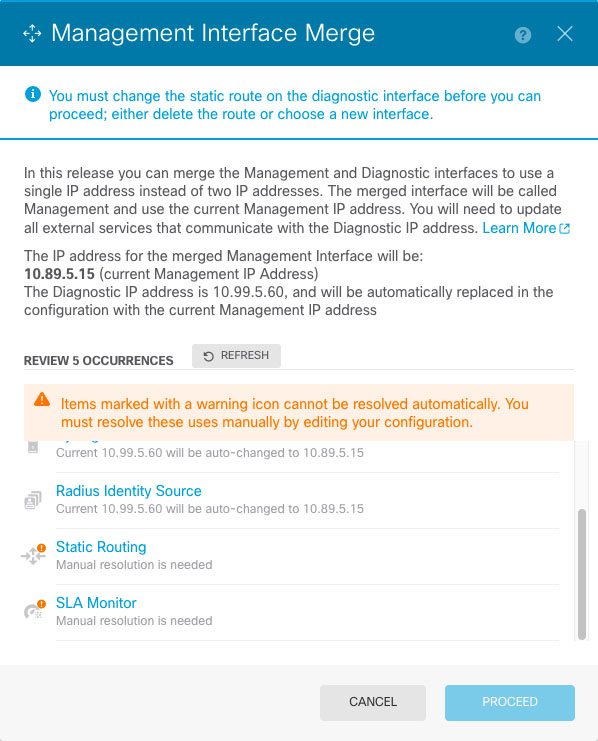
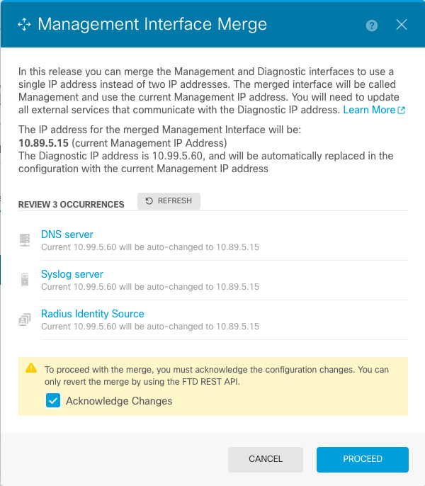
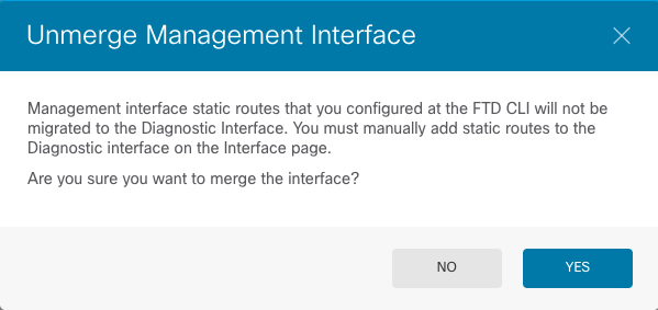
If you upgraded to 7.4 or later, and you have configuration for the Diagnostic interface, then you have the choice to merge the interfaces manually, or you can continue to use the separate Diagnostic interface. Note that support for the Diagnostic interface will be removed in a later release, so you should plan to merge the interfaces as soon as possible. To manually merge the Management and Diagnostic interfaces, see Merge the Management and Diagnostic Interfaces. Configurations that prevent an automatic merge include the following:
-
A data interface named "management"—This name is reserved for use with the merged Management interface.
-
IP Address on Diagnostic
-
DNS enabled on Diagnostic
-
Syslog, or RADIUS (for remote access VPN) source interface is Diagnostic
-
AD or RADIUS (for remote access VPN) with no source interface specified, and there is at least one interface configured as management-only (including Diagnostic)—The default route lookup for these services has changed from the management-only routing table to the data routing table, with no fallback to management. Therefore, to use a management-only interface, you must choose that specific interface instead of relying on a route lookup.
-
Static routes or SLA monitor on Diagnostic
-
FlexConfig using Diagnostic
-
DDNS for Diagnostic
For more information about how the legacy Diagnostic interface operates, see the 7.3 version of this guide.
Recommendations for Configuring a Separate Management Network
(Hardware devices.) If you want to use a separate management network, wire the physical Management interface to a switch or router.
For threat defense virtual, attach Management0/0 to a separate network from any of the data interfaces. If you are still using the default IP addresses, you will need to change either the management IP address or the inside interface IP address, as they are on the same subnet.
Then, select , edit the Management interface, and configure IPv4 or IPv6 addresses (or both) on the attached network. If you want to, you can configure a DHCP server to provide IPv4 addresses to other endpoints on the network. If there is a router with a route to the internet on the management network, use that as the gateway. Otherwise, use the data interfaces as the gateway.
Security Zones
Each interface can be assigned to a single security zone. You then apply your security policy based on zones. For example, you can assign the inside interface to the inside zone; and the outside interface to the outside zone. You can configure your access control policy to enable traffic to go from inside to outside, but not from outside to inside, for example.
Each zone has a mode that relates directly to the interface mode. You can add interfaces to the same mode security zone only.
For bridge groups, you add member interfaces to the zones, you cannot add the Bridge Virtual Interface (BVI).
You do not include the Management interface in a zone. Zones apply to data interfaces only.
You can create security zones on the Objects page.
IPv6 Addressing
You can configure two types of unicast addresses for IPv6:
-
Global—The global address is a public address that you can use on the public network. For a bridge group, you configure the global address on the Bridge Virtual Interface (BVI), not on each member interface. You cannot specify any of the following as a global address.
-
Internally reserved IPv6 addresses: fd00::/56 (from=fd00:: to= fd00:0000:0000:00ff:ffff:ffff:ffff:ffff)
-
An unspecified address, such as ::/128
-
The loopback address, ::1/128
-
multicast addresses, ff00::/8
-
Link-local addresses, fe80::/10
-
-
Link-local—The link-local address is a private address that you can only use on the directly-connected network. Routers do not forward packets using link-local addresses; they are only for communication on a particular physical network segment. They can be used for address configuration or for the Network Discovery functions such as address resolution and neighbor discovery. In a bridge group, enabling IPv6 on the BVI automatically configures link-local addresses for each bridge group member interface. Each interface must have its own address because the link-local address is only available on a segment, and is tied to the interface MAC address.
At a minimum, you need to configure a link-local address for IPv6 to operate. If you configure a global address, a link-local address is automatically configured on the interface, so you do not also need to specifically configure a link-local address. If you do not configure a global address, then you need to configure the link-local address, either automatically or manually.
Auto-MDI/MDIX Feature
For RJ-45 interfaces, the default auto-negotiation setting also includes the Auto-MDI/MDIX feature. Auto-MDI/MDIX eliminates the need for crossover cabling by performing an internal crossover when a straight cable is detected during the auto-negotiation phase. Either the speed or duplex must be set to auto-negotiate to enable Auto-MDI/MDIX for the interface. If you explicitly set both the speed and duplex to a fixed value, thus disabling auto-negotiation for both settings, then Auto-MDI/MDIX is also disabled. For Gigabit Ethernet, when the speed and duplex are set to 1000 and full, then the interface always auto-negotiates; therefore Auto-MDI/MDIX is always enabled and you cannot disable it.










 ) to the right of the interface.




 (
(

 Feedback