Best Practices: Use Cases for Threat Defense

The following topics explain some common tasks you might want to accomplish with threat defense using the device manager. These use cases assume that you completed the device configuration wizard and that you retained this initial configuration. Even if you modified the initial configuration, you should be able to use these examples to understand how to use the product.

How to Configure the Device in Device Manager

After you complete the setup wizard, you should have a functioning device with a few basic policies in place:

  • An outside and an inside interface. No other data interfaces are configured.

  • (Firepower 4100/9300) No data interfaces are pre-configured.

  • (ISA 3000) A bridge group contains 2 inside interfaces and 2 outside interfaces. You need to manually set the IP address of BVI1 to complete your setup.

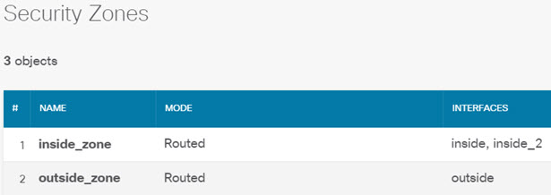
  • (Except for the Firepower 4100/9300) Security zones for the inside and outside interfaces.

  • (Except for the Firepower 4100/9300) An access rule trusting all inside to outside traffic. For the ISA 3000, there are access rules that allow all traffic from inside to outside, and from outside to inside.

  • (Except for the Firepower 4100/9300 and ISA 3000) An interface NAT rule that translates all inside to outside traffic to unique ports on the IP address of the outside interface.

  • (Except for the Firepower 4100/9300 and ISA 3000) A DHCP server running on the inside interface.

The following steps provide an overview of additional features you might want to configure. Please click the help button (?) on a page to get detailed information about each step.

Procedure


Step 1

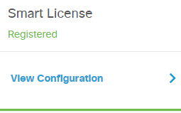
Choose Device, then click View Configuration in the Smart License group.

Click Enable for each of the optional licenses you want to use: IPS, Malware Defense, URL. If you registered the device during setup, you can also enable the RA VPN license desired. Read the explanation of each license if you are unsure of whether you need it.

If you have not registered, you can do so from this page. Click Register Device and follow the instructions. Please register before the evaluation license expires.

Step 2

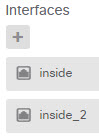
If you wired other interfaces, choose Device, then click the link in the Interfaces summary, and then click the interfaces type to view the list of interfaces.

  • For the Firepower 4100/9300, no data interfaces are pre-configured with names, IP addresses, or security zones, so you need to enable and configure any interfaces that you want to use.

  • Because the ISA 3000 comes pre-configured with a bridge group containing all data interfaces, there is no need to configure these interfaces. However, you must manually configure an IP address for the BVI. If you want to break apart the bridge group, you can edit it to remove the interfaces you want to treat separately. Then you can configure those interfaces as hosting separate networks.

    For other models, you can create a bridge group for the other interfaces, or configure separate networks, or some combination of both.

  • For the Firepower 1010, all interfaces except for Ethernet1/1 (outside) are access mode switch ports assigned to VLAN1 (inside). You can change switch ports to be firewall ports; add new VLAN interfaces and assign switch ports to them; or configure trunk mode switch ports.

Click the edit icon (edit icon) for each interface to define the IP address and other settings.

The following example configures an interface to be used as a “demilitarized zone” (DMZ), where you place publically-accessible assets such as your web server. Click Save when you are finished.
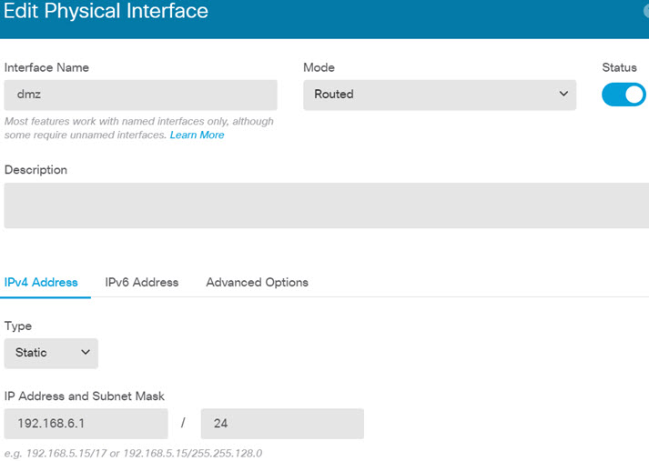

Edit interface.

Step 3

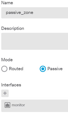
If you configured new interfaces, choose Objects, then select Security Zones from the table of contents.

Edit or create new zones as appropriate. Each interface must belong to a zone, because you configure policies based on security zones, not interfaces. You cannot put the interfaces in zones when configuring them, so you must always edit the zone objects after creating new interfaces or changing the purpose of existing interfaces.

The following example shows how to create a new dmz-zone for the dmz interface.
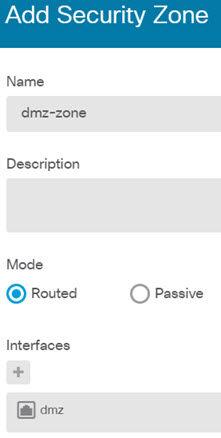

Add security zone.

Step 4

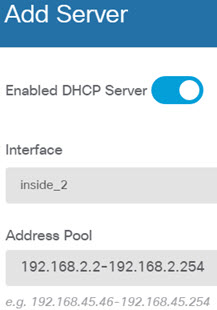
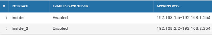
If you want internal clients to use DHCP to obtain an IP address from the device, choose Device, then System Settings > DHCP Server. Select the DHCP Servers tab.

There is already a DHCP server configured for the inside interface, but you can edit the address pool or even delete it. If you configured other inside interfaces, it is very typical to set up a DHCP server on those interfaces. Click + to configure the server and address pool for each inside interface.

You can also fine-tune the WINS and DNS list supplied to clients on the Configuration tab.

The following example shows how to set up a DHCP server on the inside2 interface with the address pool 192.168.4.50-192.168.4.240.
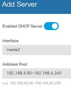

Add DHCP server.

Step 5

Choose Device, then click View Configuration in the Routing group and configure a default route.

The default route normally points to the upstream or ISP router that resides off the outside interface. A default IPv4 route is for any-ipv4 (0.0.0.0/0), whereas a default IPv6 route is for any-ipv6 (::0/0). Create routes for each IP version you use. If you use DHCP to obtain an address for the outside interface, you might already have the default routes that you need.

The routes you define on this page are for the data interfaces only. They do not impact the management interface. Set the management gateway on System Settings > Management Interface.

The following example shows a default route for IPv4. In this example, isp-gateway is a network object that identifies the IP address of the ISP gateway (you must obtain the address from your ISP). You can create this object by clicking Create New Network at the bottom of the Gateway drop-down list.
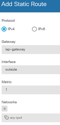

Add default route.

Step 6

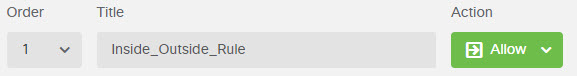
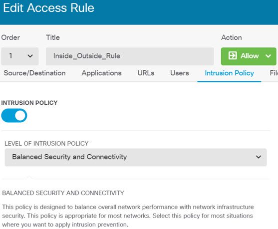
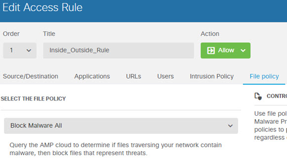
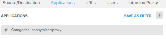
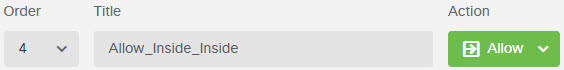
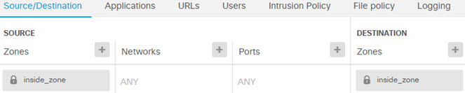
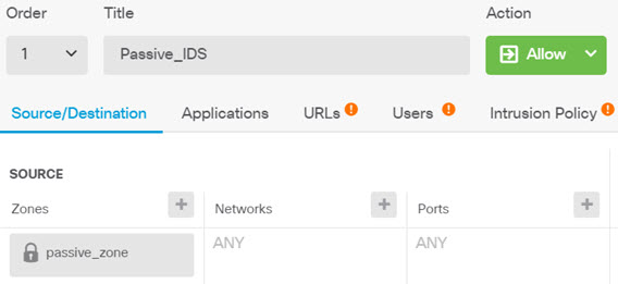
Choose Policies and configure the security policies for the network.

The device setup wizard enables traffic flow between the inside-zone and outside-zone, and interface NAT for all interfaces when going to the outside interface. Even if you configure new interfaces, if you add them to the inside-zone object, the access control rule automatically applies to them.

However, if you have multiple inside interfaces, you need an access control rule to allow traffic flow from inside-zone to inside-zone. If you add other security zones, you need rules to allow traffic to and from those zones. These would be your minimum changes.

In addition, you can configure other policies to provide additional services, and fine-tune NAT and access rules to get the results that your organization requires. You can configure the following policies:

  • SSL Decryption—If you want to inspect encrypted connections (such as HTTPS) for intrusions, malware, and so forth, you must decrypt the connections. Use the SSL decryption policy to determine which connections need to be decrypted. The system re-encrypts the connection after inspecting it.

  • Identity—If you want to correlate network activity to individual users, or control network access based on user or user group membership, use the identity policy to determine the user associated with a given source IP address.

  • Security Intelligence—Use the Security Intelligence policy to quickly drop connections from or to selected IP addresses or URLs. By blocking known bad sites, you do not need to account for them in your access control policy. Cisco provides regularly updated feeds of known bad addresses and URLs so that the Security Intelligence block lists update dynamically. Using feeds, you do not need to edit the policy to add or remove items in the block lists.

  • NAT (Network Address Translation)—Use the NAT policy to convert internal IP addresses to externally routeable addresses.

  • Access Control—Use the access control policy to determine which connections are allowed on the network. You can filter by security zone, IP address, protocol, port, application, URL, user or user group. You also apply intrusion and file (malware) policies using access control rules. Use this policy to implement URL filtering.

  • Intrusion—Use the intrusion policies to inspect for known threats. Although you apply intrusion policies using access control rules, you can edit the intrusion policies to selectively enable or disable specific intrusion rules.

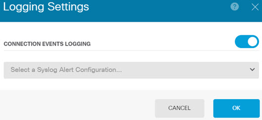
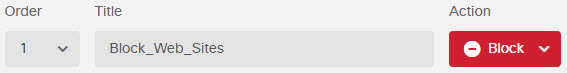
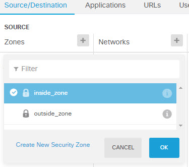
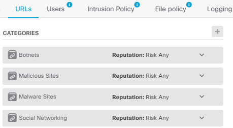
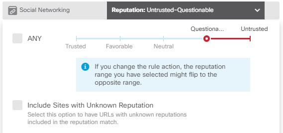
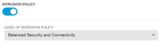
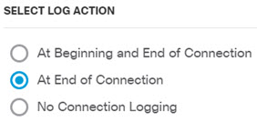
The following example shows how to allow traffic between the inside-zone and dmz-zone in the access control policy. In this example, no options are set on any of the other tabs except for Logging, where At End of Connection is selected.
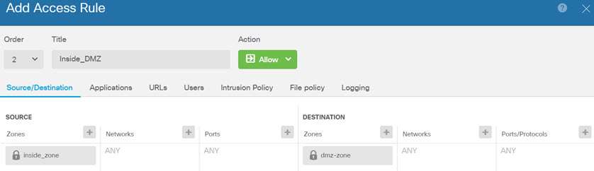

Add access control rule.

Step 7

Commit your changes.

  1. Click the Deploy Changes icon in the upper right of the web page.

    Deploy changes button, highlighted when there are changes to deploy.

  2. Click the Deploy Now button.

    You can wait until deployment completes, or click OK and check the task list or deployment history later.


How to Gain Insight Into Your Network Traffic

After completing initial device setup, you have an access control policy that allows all inside traffic access to the Internet or other upstream network, and a default action to block all other traffic. Before you create additional access control rules, you might find it beneficial to gain insight into the traffic that is actually occurring on your network.

You can use the monitoring capabilities of the device manager to analyze network traffic. Device Manager reporting helps you answer the following questions:

  • What is my network being used for?

  • Who is using the network the most?

  • Where are my users going?

  • What devices are they using?

  • What access control rules (policies) are being hit the most?

The initial access rule can provide some insight into traffic, including policies, destinations, and security zones. But to obtain user information, you need to configure an identity policy that requires users to authenticate (identify) themselves. To obtain information on applications used on the network, you need to make some additional adjustments.

The following procedure explains how to set up the threat defense device to monitor traffic and provides an overview of the end-to-end process of configuring and monitoring policies.


Note


This procedure does not provide insight into the web site categories and reputations of sites visited by users, so you cannot see meaningful information in the URL categories dashboard. You must implement category-based URL filtering, and enable the URL license, to obtain category and reputation data. If you just want to obtain this information, you can add a new access control rule that allows access to an acceptable category, such as Finance, and make it the first rule in the access control policy. For details on implementing URL filtering, see How to Implement an Acceptable Use Policy (URL Filtering).


Procedure


Step 1

To gain insight into user behavior, you need to configure an identity policy to ensure that the user associated with a connection is identified.

By enabling the identity policy, you can collect information about who is using the network, and what resources they are using. This information is available in the User monitoring dashboard. User information is also available for connection events shown in Event Viewer.

In this example, we will implement active authentication to acquire user identity. With active authentication, the device prompts the user for username and password. Users are authenticated only when they use a web browser for HTTP connections.

If a user fails to authenticate, the user is not prevented from making web connections. This just means that you do not have user identity information for the connections. If you want, you can create an access control rule to drop traffic for Failed Authentication users.

  1. Click Policies in the main menu, then click Identity.

    The identity policy is initially disabled. When using active authentication, the identity policy uses your Active Directory server to authenticate users and associate them with the IP address of the workstation they are using. Subsequently, the system will identify traffic for that IP address as being the user's traffic.

  2. Click Enable Identity Policy.

  3. Click the Create Identity Rule button, or the + button, to create the rule to require active authentication.

    In this example, we will assume you want to require authentication for everyone.

  4. Enter a Name for the rule, which can be anything you choose, for example, Require_Authentication.

  5. On the Source/Destination tab, leave the defaults, which apply to Any criteria.

    You can constrain the policy as you see fit to a more limited set of traffic. However, active authentication will only be attempted for HTTP traffic, so it does not matter that non-HTTP traffic matches the source/destination criteria. For more details about identity policy properties, see Configure Identity Rules

  6. For Action, select Active Auth.

    Assuming you have not configured the identity policy settings, the Identity Policy Configuration dialog box will open because there are some undefined settings.

  7. Configure the Captive Portal and SSL Decryption settings that are required for active authentication.

    When an identity rule requires active authentication for a user, the user is redirected to the captive portal port and then they are prompted to authenticate. Captive portal requires SSL decryption rules, which the system will generate automatically, but you must select the certificate to use for the SSL decryption rules.

    • Server Certificate—Select the internal certificate to present to users during active authentication. You can select the predefined self-signed DefaultInternalCertificate, or you can click Create New Internal Certificate and upload a certificate that your browsers already trust.

      Users will have to accept the certificate if you do not upload a certificate that their browsers already trust.

    • Redirect to Host Name—Select the network object that defines the fully-qualified host name of the interface that should be used as the captive portal for active authentication requests. Click Create New Network if the object does not exist.

      The FQDN must resolve to the IP address of one of the interfaces on the device. By using an FQDN, you can assign a certificate for active authentication that the client will recognize, thus avoiding the untrusted certificate warning users get when being redirected to an IP address. The certificate can specify the FQDN, a wildcard FQDN, or multiple FQDNs in the Subject Alternate Names (SAN) in the certificate.

      If an identity rule requires active authentication for a user, but you do not specify a redirect FQDN, the user is redirected to the captive portal port on the interface through which they are connected.

    • Port—The captive portal port. The default is 885 (TCP). If you configure a different port, it must be in the range 1025-65535.

    • Decrypt Re-Sign Certificate—Select the internal CA certificate to use for rules that implement decryption with re-signed certificates. You can use the pre-defined NGFW-Default-InternalCA certificate (the default), or one that you created or uploaded. If the certificate does not yet exist, click Create Internal CA to create it. (You are prompted for the decrypt re-sign certificate only if you have not yet enabled the SSL decryption policy.)

      If you have not already installed the certificate in client browsers, click the download button (Download button.) to obtain a copy. See the documentation for each browser for information on how to install the certificate. Also see Downloading the CA Certificate for Decrypt Re-Sign Rules.

    Example:

    The Identity Policy Configuration dialog box should now look like the following.


    Identity policy active authentication options.

  8. Click Save to save the active authentication settings.

    The Active Authentication tab now appears below the Action setting.

  9. On the Active Authentication tab, select HTTP Negotiate.

    This allows the browser and directory server to negotiate the strongest authentication protocol, in order, NTLM, then HTTP basic.

    Note


    If you do not supply a Redirect to Host Name FQDN, the HTTP Basic, HTTP Response Page, and NTLM authentication methods redirect the user to the captive portal using the IP address of the interface. However, for HTTP Negotiate, the user is redirected using the fully-qualified DNS name firewall-hostname.AD-domain-name . If you want to use HTTP Negotiate without a Redirect to Host Name FQDN, you must also update your DNS server to map this name to the IP addresses of all inside interfaces where you are requiring active authentication. Otherwise, the redirection cannot complete, and users cannot authenticate. We recommend that you always provide a Redirect to Host Name FQDN to ensure consistent behavior regardless of authentication method. If you cannot, or do not want to, update the DNS server, select one of the other authentication methods.

  10. For AD Identity Source, click Create New Identity Realm.

    If you already created your realm server object, simply select it and skip the steps for configuring the server.

    Fill in the following fields, then click OK.

    • Name—A name for the directory realm.

    • Type—The type of directory server. Active Directory is the only supported type, and you cannot change this field.

    • Directory Username, Directory Password—The distinguished username and password for a user with appropriate rights to the user information you want to retrieve. For Active Directory, the user does not need elevated privileges. You can specify any user in the domain. The username must be fully qualified; for example, Administrator@example.com (not simply Administrator).

      Note


      The system generates ldap-login-dn and ldap-login-password from this information. For example, Administrator@example.com is translated as cn=adminisntrator,cn=users,dc=example,dc=com. Note that cn=users is always part of this translation, so you must configure the user you specify here under the common name “users” folder.

    • Base DN—The directory tree for searching or querying user and group information, that is, the common parent for users and groups. For example, dc=example,dc=com. For information on finding the base DN, see Determining the Directory Base DN.

    • AD Primary Domain— The fully qualified Active Directory domain name that the device should join. For example, example.com.

    • Hostname/IP Address—The hostname or IP address of the directory server. If you use an encrypted connection to the server, you must enter the fully-qualified domain name, not the IP address.

    • Port—The port number used for communications with the server. The default is 389. Use port 636 if you select LDAPS as the encryption method.

    • Encryption—To use an encrypted connection for downloading user and group information, select the desired method, STARTTLS or LDAPS. The default is None, which means that user and group information is downloaded in clear text.

      • STARTTLS negotiates the encryption method, and uses the strongest method supported by the directory server. Use port 389. This option is not supported if you use the realm for remote access VPN.

      • LDAPS requires LDAP over SSL. Use port 636.

    • Trusted CA Certificate—If you select an encryption method, upload a Certificate Authority (CA) certificate to enable a trusted connection between the system and the directory server. If you are using a certificate to authenticate, the name of the server in the certificate must match the server Hostname / IP Address. For example, if you use 10.10.10.250 as the IP address but ad.example.com in the certificate, the connection fails.

    Example:

    For example, the following image shows how to create an unencrypted connection for the ad.example.com server. The primary domain is example.com, and the directory username is Administrator@ad.example.com. All user and group information is under the Distinguished Name (DN) ou=user,dc=example,dc=com.


    Directory realm properties.

  11. For AD Identity Source, select the object you just created.

    The rule should look similar to the following.


    Active authentication identity rule.

  12. Click OK to add the rule.

    If you look in the upper right of the window, you can see that the Deploy icon button now has a dot, which indicates that there are undeployed changes. Making changes in the user interface is not sufficient for getting the changes configured on the device, you must deploy changes. Thus, you can make a set of related changes before you deploy them, so that you do not face the potential problems of having a partially-configured set of changes running on the device. You will deploy changes later in this procedure.


    Deploy Changes icon when there are undeployed changes.

Step 2

Change the action on the Inside_Outside_Rule access control rule to Allow.

The Inside_Outside_Rule access rule is created as a trust rule. However, trusted traffic is not inspected, so the system cannot learn about some of the characteristics of trusted traffic, such as application, when the traffic matching criteria does not include application or other conditions besides zone, IP address, and port. If you change the rule to allow rather than trust traffic, the system fully inspects the traffic.

Note


( ISA 3000.) Also consider changing the Outside_Inside_Rule, Inside_Inside_Rule and Outside_Outside_Rule from Trust to Allow.

  1. Click Access Control on the Policies page.

  2. Hover over the Actions cell on the right side of the Inside_Outside_Rule row to expose the edit and delete icons, and click the edit icon (edit icon) to open the rule.

  3. Select Allow for the Action.


    Changing access rule action to Allow.

  4. Click OK to save the change.

Step 3

Enable logging on the access control policy default action.

Dashboards contain information about connections only if the connection matches an access control rule that enables connection logging. The Inside_Outside_Rule enables logging, but the default action has logging disabled. Thus, dashboards show information for the Inside_Outside_Rule only, and do not reflect connections that do not match any rules.

  1. Click anywhere in the default action at the bottom of the access control policy page.


    Access control policy default action.

  2. Select Select Log Action > At Beginning and End of Connection.

  3. Click OK.

Step 4

Set an update schedule for the vulnerability database (VDB).

Cisco regularly releases updates to the VDB, which includes the application detectors that can identify the application used in a connection. You should update the VDB on a regular basis. You can either manually download updates, or you can set up a regular schedule. The following procedure shows how to set up a schedule. By default, VDB updates are disabled, so you need to take action to get VDB updates.

  1. Click Device.

  2. Click View Configuration in the Updates group.


    Updates group, Device Dashboard.

  3. Click Configure in the VDB group.


    VDB group, Updates page.

  4. Define the update schedule.

    Choose a time and frequency that will not be disruptive to your network. Also, please understand that the system will do an automatic deployment after downloading the update. This is necessary to activate the new detectors. Thus, any configuration changes that you have made and saved but have not yet deployed will also be deployed.

    For example, the following schedule updates the VDB once a week on Sunday at 12:00 AM (using the 24-hour clock notation).


    Recurring schedule for VDB updates.

  5. Click Save.

Step 5

Commit your changes.

  1. Click the Deploy Changes icon in the upper right of the web page.

    Deploy changes button, highlighted when there are changes to deploy.

  2. Click the Deploy Now button.

    You can wait until deployment completes, or click OK and check the task list or deployment history later.


What to do next

At this point, the monitoring dashboards and events should start showing information about users and applications. You can evaluate this information for undesirable patterns and develop new access rules to constrain unacceptable use.

If you want to start collecting information about intrusions and malware, you need to enable intrusion and file policies on one or more access rule. You also need to enable the licenses for those features.

If you want to start collecting information about URL categories, you must implement URL filtering.

How to Block Threats

You can implement next generation Intrusion Prevention System (IPS) filtering by adding intrusion policies to your access control rules. Intrusion policies analyze network traffic, comparing the traffic contents against known threats. If a connection matches a threat you are monitoring, the system drops the connection, thus preventing the attack.

All other traffic handling occurs before network traffic is examined for intrusions. By associating an intrusion policy with an access control rule, you are telling the system that before it passes traffic that matches the access control rule's conditions, you first want to inspect the traffic with an intrusion policy.

You can configure intrusion policies on rules that allow traffic only. Inspection is not performed on rules set to trust or block traffic. In addition, you can configure an intrusion policy as part of the default action if the default action is allow.

The intrusion policies are designed by the Cisco Talos Intelligence Group (Talos), who set the intrusion and preprocessor rule states and advanced settings. You can create your own custom policies based on the Talos policies if you are using Snort 3 as the inspection engine.

Besides inspecting traffic that you allow for potential intrusions, you can use the Security Intelligence policy to preemptively block all traffic to or from known bad IP addresses, or to known bad URLs.

Procedure


Step 1

If you have not already done so, enable the IPS license.

You must enable the IPS license to use intrusion policies and Security Intelligence. If you are currently using the evaluation license, you are enabling an evaluation version of the license. If you have registered the device, you must purchase the required license and add it to your Smart Software Manager account on Cisco.com.

  1. Click Device.

  2. Click View Configuration in the Smart License group.


    Smart License group on the device dashboard.

  3. Click Enable in the IPS group.

    The system registers the license with your account, or activates the evaluation license, as appropriate. The group should indicate that the license is enabled, and the button changes to a Disable button.

Step 2

Select an intrusion policy for one or more access rules.

Determine which rules cover traffic that should be scanned for threats. For this example, we will add intrusion inspection to the Inside_Outside_Rule.

  1. Click Policies in the main menu.

    Ensure that the Access Control policy is displayed.

  2. Hover over the Actions cell on the right side of the Inside_Outside_Rule row to expose the edit and delete icons, and click the edit icon (edit icon) to open the rule.

  3. If you have not already done so, select Allow for the Action.


    Changing access rule action to Allow.

  4. Click the Intrusion Policy tab.

  5. Click the Intrusion Policy toggle to enable it, then select the intrusion policy.

    The Balanced Security and Connectivity policy is appropriate for most networks. It provides a good intrusion defense without being overly aggressive, which has the potential of dropping traffic that you might not want to be dropped. If you determine that too much traffic is getting dropped, you can ease up on intrusion inspection by selecting the Connectivity over Security policy.

    If you need to be aggressive about security, try the Security over Connectivity policy. The Maximum Detection policy offers even more emphasis on network infrastructure security with the potential for even greater operational impact.


    Intrusion policy tab.

  6. Click OK to save the change.

Step 3

(Optional.) Go to Policies > Intrusion, click the gear icon, and configure a syslog server for the intrusion policy.

Intrusion events do not use the syslog server configured for the access control rule.

Step 4

Set an update schedule for the intrusion rule database.

Cisco regularly releases updates to the intrusion rule database, which is used by intrusion policies to determine whether connections should be dropped. You should update the rule database on a regular basis. You can either manually download updates, or you can set up a regular schedule. The following procedure shows how to set up a schedule. By default, database updates are disabled, so you need to take action to get updated rules.

  1. Click Device.

  2. Click View Configuration in the Updates group.


    Updates group, Device Dashboard.

  3. Click Configure in the Rule group.


    Rule group, Updates page.

  4. Define the update schedule.

    Choose a time and frequency that will not be disruptive to your network. Also, please understand that the system will do an automatic deployment after downloading the update. This is necessary to activate the new rules. Thus, any configuration changes that you have made and saved but have not yet deployed will also be deployed.

    For example, the following schedule updates the rule database once a week on Monday at 12:00 AM (using the 24-hour clock notation).


    Recurring schedule for rule database updates.

  5. Click Save.

Step 5

Configure the Security Intelligence policy to preemptively drop connections with known bad hosts and sites.

By using Security Intelligence to block connections with hosts or sites that are known to be threats, you save your system the time needed to do deep packet inspection to identify threats in each connection. Security Intelligence provides an early block of undesirable traffic, leaving more system time to handle the traffic you really care about.

  1. Click Device, then click View Configuration in the Updates group.

  2. Click Update Now in the Security Intelligence Feeds group.

  3. Also, click Configure and set a recurring update for the feeds. The default, Hourly, is appropriate for most networks but you can decrease the frequency if necessary.

  4. Click Policies, then click the Security Intelligence policy.

  5. Click Enable Security Intelligence if you have not already enabled the policy.

  6. On the Network tab, click + in the block/drop list, and select all of the feeds on the Network Feeds tab. You can click the i button next to a feed to read a description of each feed.

    If you see a message that there are no feeds yet, please try again later. The feeds download has not yet completed. If this problem persists, ensure that there is a path between the management IP address and the Internet.

  7. Click OK to add the selected feeds.

    If you know of additional bad IP addresses, you can click + > Network Objects and add the objects that contain the addresses. You can click Create New Network Object at the bottom of the list to add them now.

  8. Click the URL tab, then click + > URL Feeds in the block/drop list, and select all of the URL feeds. Click OK to add them to the list.

    Similar to the network list, you can add your own URL objects to the list to block additional sites that are not in the feeds. Click + > URL Objects. You can add new objects by clicking Create New URL Object at the end of the list.

  9. Click the gear icon, and enable Connection Events Logging, to enable the policy to generate Security Intelligence events for matched connections. Click OK to save your changes.

    If you do not enable connection logging, you will have no data to use to evaluate whether the policy is performing to expectations. If you have an external syslog server defined, you can select it now so that the events are also sent to that server.


    Enabling connection logging for Security Intelligence.

  10. As needed, you can add network or URL objects to the Do Not Block list on each tab to create exceptions to the blocked list.

    The Do Not Block lists are not real "allow" lists. They are exception lists. If an address or URL in the exception list also appears in the blocked list, the connection for the address or URL is allowed to pass on to the access control policy. This way, you can block a feed, but if you later find that a desirable address or site is being blocked, you can use the exception list to override that block without needing to remove the feed entirely. Keep in mind that these connections are subsequently evaluated by access control, and if configured, an intrusion policy. Thus, if any connections do contain threats, they can be identified and blocked during intrusion inspection.

    Use the Access and SI Rules dashboard, and the Security Intelligence view in the Event Viewer, to determine what traffic is actually being dropped by the policy, and whether you need to add addresses or URLs to the Do Not Block lists.

Step 6

Commit your changes.

  1. Click the Deploy Changes icon in the upper right of the web page.

    Deploy changes button, highlighted when there are changes to deploy.

  2. Click the Deploy Now button.

    You can wait until deployment completes, or click OK and check the task list or deployment history later.


What to do next

At this point, the monitoring dashboards and events should start showing information about attackers, targets, and threats, if any intrusions are identified. You can evaluate this information to determine if your network needs more security precautions, or if you need to reduce the level of intrusion policy you are using.

For Security Intelligence, you can see policy hits on the Access and SI Rules dashboard. You can also see Security Intelligence events in the Event Viewer. Security Intelligence blocks are not reflected in intrusion threat information, because the traffic is blocked before it can be inspected.

How to Block Malware

Users are continually at risk of obtaining malicious software, or malware, from Internet sites or other communication methods, such as e-mail. Even trusted web sites can be hijacked to serve malware to unsuspecting users. Web pages can contain objects coming from different sources. These objects can include images, executables, Javascript, advertisements, and so forth. Compromised web sites often incorporate objects hosted on external sources. Real security means looking at each object individually, not just the initial request.

Use file policies to detect malware using malware defense. You can also use file policies to perform file control, which allows control over all files of a specific type regardless of whether the files contain malware.

Malware defense uses the Secure Malware Analytics Cloud to retrieve dispositions for possible malware detected in network traffic. The management interface must have a path to the Internet to reach the Secure Malware Analytics Cloud and perform malware lookups. When the device detects an eligible file, it uses the file's SHA-256 hash value to query the Secure Malware Analytics Cloud for the file's disposition. The possible disposition can be clean, malware, or unknown (no clear verdict). If the Secure Malware Analytics Cloud is unreachable, the disposition is unknown.

By associating a file policy with an access control rule, you are telling the system that before it passes traffic that matches the access control rule's conditions, you first want to inspect any files in the connection.

You can configure file policies on rules that allow traffic only. Inspection is not performed on rules set to trust or block traffic.

Procedure


Step 1

If you have not already done so, enable the Malware Defense and IPS licenses.

You must enable the Malware Defense to use file policies in addition to the IPS license, which is required for intrusion policies. If you are currently using the evaluation license, you are enabling an evaluation version of the licenses. If you have registered the device, you must purchase the required licenses and add them to your Smart Software Manager account on Cisco.com.

  1. Click Device.

  2. Click View Configuration in the Smart License group.


    Smart License group on the device dashboard.

  3. Click Enable in the Malware Defense group, and if not already enabled, the IPS group.

    The system registers the license with your account, or activates the evaluation license, as appropriate. The group should indicate that the license is enabled, and the button changes to a Disable button.

Step 2

Select a file policy for one or more access rules.

Determine which rules cover traffic that should be scanned for malware. For this example, we will add file inspection to the Inside_Outside_Rule.

  1. Click Policies in the main menu.

    Ensure that the Access Control policy is displayed.

  2. Hover over the Actions cell on the right side of the Inside_Outside_Rule row to expose the edit and delete icons, and click the edit icon (edit icon) to open the rule.

  3. If you have not already done so, select Allow for the Action.


    Changing access rule action to Allow.

  4. Click the File Policy tab.

  5. Click the file policy you want to use.

    Your main choice is between Block Malware All, which drops any files that are considered malware, or Cloud Lookup All, which queries the Secure Malware Analytics Cloud to determine the file's disposition, but does no blocking. If you want to first see how files are being evaluated, use cloud lookup. You can switch to the blocking policy later if you are satisfied with how files are being evaluated.

    There are other policies available that block malware. These policies are coupled with file control, blocking the upload of Microsoft Office, or Office and PDF, documents. That is, these policies prevent users from sending these file types to other networks in addition to blocking malware. You can select these policies if they fit your needs.

    For this example, select Block Malware All.


    Block Malware policy selected in access control rule.

  6. Click the Logging tab and verify that Log Files under File Events is selected.

    By default, file logging is enabled whenever you select a file policy. You must enable file logging to get file and malware information in events and dashboards.


    File logging enabled.

  7. Click OK to save the change.

Step 3

Commit your changes.

  1. Click the Deploy Changes icon in the upper right of the web page.

    Deploy changes button, highlighted when there are changes to deploy.

  2. Click the Deploy Now button.

    You can wait until deployment completes, or click OK and check the task list or deployment history later.


What to do next

At this point, the monitoring dashboards and events should start showing information about file types and file and malware events, if any files or malware are transmitted. You can evaluate this information to determine if your network needs more security precautions related to file transmissions.

How to Implement an Acceptable Use Policy (URL Filtering)

You might have an acceptable use policy for your network. Acceptable use policies differentiate between network activity that is appropriate in your organization and activity that is considered inappropriate. These policies are typically focused on Internet usage, and are geared towards maintaining productivity, avoiding legal liabilities (for example, maintaining a non-hostile workplace), and in general controlling web traffic.

You can use URL filtering to define an acceptable use policy with access policies. You can filter on broad categories, such as Gambling, so that you do not need to identify every individual web site that should be blocked. For category matches, you can also specify the relative reputation of sites to allow or block. If a user attempts to browse to any URL with that category and reputation combination, the session is blocked.

Using category and reputation data also simplifies policy creation and administration. It grants you assurance that the system will control web traffic as expected. Finally, because Cisco's threat intelligence is continually updated with new URLs, as well as new categories and risks for existing URLs, you can ensure that the system uses up-to-date information to filter requested URLs. Malicious sites that represent security threats such as malware, spam, botnets, and phishing may appear and disappear faster than you can update and deploy new policies.

The following procedure explains how to implement an acceptable use policy using URL filtering. For purposes of this example, we will block sites of any reputation in several categories, risky Social Networking sites, and an unclassified site, badsite.example.com.

Procedure


Step 1

If you have not already done so, enable the URL license.

You must enable the URL license to use URL category and reputation information, or to see the information in dashboards and events. If you are currently using the evaluation license, you are enabling an evaluation version of the license. If you have registered the device, you must purchase the required license and add it to your Smart Software Manager account on Cisco.com.

  1. Click Device.

  2. Click View Configuration in the Smart License group.


    Smart License group on the device dashboard.

  3. Click Enable in the URL group.

    The system registers the license with your account, or activates the evaluation license, as appropriate. The group should indicate that the license is enabled, and the button changes to a Disable button.

Step 2

Create a URL filtering access control rule.

You might want to first see the categories for sites your users are visiting before making a blocking rule. If that is the case, you can create a rule with the Allow action for an acceptable category, such as Finance. Because all web connections must be inspected to determine if the URL belongs to this category, you would get category information even for non-Finance sites.

But there are probably URL categories that you already know you want to block. A blocking policy also forces inspection, so you get category information on connections to unblocked categories, not just the blocked categories.

  1. Click Policies in the main menu.

    Ensure that the Access Control policy is displayed.

  2. Click + to add a new rule.

  3. Configure the order, title, and action.

    • Order—The default is to add new rules to the end of the access control policy. However, you must place this rule ahead of (above) any rule that would match the same Source/Destination and other criteria, or the rule will never be matched (a connection matches one rule only, and that is the first rule it matches in the table). For this rule, we will use the same Source/Destination as the Inside_Outside_Rule created during initial device configuration. You might have created other rules as well. To maximize access control efficiency, it is best to have specific rules early, to ensure the quickest decision on whether a connection is allowed or dropped. For the purposes of this example, select 1 as the rule order.

    • Title—Give the rule a meaningful name, such as Block_Web_Sites.

    • Action—Select Block.


    URL filtering rule order and action.

  4. On the Source/Destination tab, click + for Source > Zones, select inside_zone, then click OK in the zones dialog box.

    Adding any of the criteria works the same way. Clicking + opens a little dialog box, where you click the items you want to add. You can click multiple items, and clicking a selected item de-selects it; the check marks indicate the selected items. But nothing is added to the policy until you click the OK button; simply selecting the items is not sufficient.


    Selecting the inside security zone.

  5. Using the same technique, select outside_zone for Destination > Zones.


    Completed source/destination criteria.

  6. Click the URLs tab.

  7. Click the + for Categories, and select the categories you want to fully or partially block.

    For purposes of this example, select Botnets, Malicious Sites, Malware Sites, and Social Networking. There are additional categories that you would most likely want to block. If you know of a site that you want to block, but you are unsure of the category, enter the URL in the in the URL to Check field and click Go. You will be taken to a web site that shows the results of the lookup.


    Selected URL categories.

  8. To implement reputation-sensitive blocking for the Social Networking category, click Reputation: Risk Any for that category, deselect Any, then move the slider to Questionable. Click away from the slider to close it.


    Reputation slider

    The left of the reputation slider indicates sites that will be allowed, the right side are sites that will be blocked. In this case, only Social Networking sites with reputations in the Questionable and Untrusted ranges will be blocked. Thus, your users should be able to get to commonly-used Social Networking sites, where there are fewer risks.

    Select the Include Sites with Unknown Reputation option to have URLs with unknown reputation included in the reputation match. New sites typically are unrated, and there can be other reasons a site's reputation is unknown or cannot be determined.

    Using reputation, you can selectively block sites within a category you otherwise want to allow.

  9. Click the + next to the URLS list to the left of the categories list.

  10. At the bottom of the popup dialog box, click the Create New URL link.

  11. Enter badsite.example.com for both the name and URL, then click OK to create the object.

    You can name the object the same as the URL or give the object a different name. For the URL, do not include the protocol portion of the URL, just add the server name.


    URL object.

  12. Select the new object, then click OK.

    Adding new objects while editing policies simply adds the object to the list. The new object is not automatically selected.


    Completed URL criteria.

  13. Click the Logging tab and select Select Log Action > At Beginning and End of Connection.

    You must enable logging to get category and reputation information into the web category dashboard and connection events.

  14. Click OK to save the rule.

Step 3

(Optional.) Set preferences for URL filtering.

When you enable the URL license, the system automatically enables updates to the web category database. The system checks for updates every 30 minutes, although the data is typically updated once per day. You can turn off these updates if for some reason you do not want them.

  1. Click Device.

  2. Click System Settings > Traffic Settings > URL Filtering Preferences.

  3. Under URL Query Source, select the recommended option, Local Database and Cisco Cloud.

    If the installed URL database does not have a categorization for a site, the Cisco Cloud might have one. The cloud returns the category and reputation, and your category-based rules can then be applied correctly to the URL request. Selecting this option is important for lower-end systems, which install a smaller URL database due to memory limitations.

    Alternatively, you can instead restrict lookups to the local database or the Cisco Cloud.

  4. Select a reasonable URL Time to Live, such as 24 hours.

  5. Click Save.

Step 4

Commit your changes.

  1. Click the Deploy Changes icon in the upper right of the web page.

    Deploy changes button, highlighted when there are changes to deploy.

  2. Click the Deploy Now button.

    You can wait until deployment completes, or click OK and check the task list or deployment history later.


What to do next

At this point, the monitoring dashboards and events should start showing information about URL categories and reputations, and which connections were dropped. You can evaluate this information to determine if your URL filtering is dropping just those sites that are objectionable, or if you need to ease up on the reputation setting for certain categories.

Consider informing users beforehand that you will be blocking access to web sites based on their categorization and reputation.

How to Control Application Usage

The Web has become the ubiquitous platform for application delivery in the enterprise, whether that is browser based application platforms, or rich media applications that use web protocols as the transport in and out of enterprise networks.

Threat Defense inspects connections to determine the application being used. This makes it possible to write access control rules targeted at applications, rather than just targeting specific TCP/UDP ports. Thus, you can selectively block or allow web-based applications even though they use the same port.

Although you can select specific applications to allow or block, you can also write rules based on type, category, tag, risk, or business relevance. For example, you could create an access control rule that identifies and blocks all high risk, low business relevance applications. If a user attempts to use one of those applications, the session is blocked.

Cisco frequently updates and adds additional application detectors via system and vulnerability database (VDB) updates. Thus, a rule blocking high risk applications can automatically apply to new applications without you having to update the rule manually.

In this use case, we will block any application that belongs to the anonymizer/proxy category.

Before you begin

This use case assumes that you completed the use case How to Gain Insight Into Your Network Traffic. That use case explains how to collect application usage information, which you can analyze in the Applications dashboard. Understanding what applications are actually being used can help you design effective application-based rules. The use case also explains how to schedule VDB updates, which will not be repeated here. Ensure that you update the VDB regularly so that applications can be correctly identified.

Procedure


Step 1

Create the application-based access control rule.

  1. Click Policies in the main menu.

    Ensure that the Access Control policy is displayed.

  2. Click + to add a new rule.

  3. Configure the order, title, and action.

    • Order—The default is to add new rules to the end of the access control policy. However, you must place this rule ahead of (above) any rule that would match the same Source/Destination and other criteria, or the rule will never be matched (a connection matches one rule only, and that is the first rule it matches in the table). For this rule, we will use the same Source/Destination as the Inside_Outside_Rule created during initial device configuration. You might have created other rules as well. To maximize access control efficiency, it is best to have specific rules early, to ensure the quickest decision on whether a connection is allowed or dropped. For the purposes of this example, select 1 as the rule order.

    • Title—Give the rule a meaningful name, such as Block_Anonymizers.

    • Action—Select Block.


    Application rule order and action.

  4. On the Source/Destination tab, click + for Source > Zones, select inside_zone, then click OK in the zones dialog box.


    Selecting the inside security zone.

  5. Using the same technique, select outside_zone for Destination > Zones.


    Completed source/destination criteria.

  6. Click the Applications tab.

  7. Click the + for Applications, and then click the Advanced Filter link at the bottom of the popup dialog box.

    Although you can create application filter objects beforehand and select them on the Application Filters list here, you can also specify criteria directly in the access control rule, and optionally save the criteria as a filter object. Unless you are writing a rule for a single application, it is easier to use the Advanced Filter dialog box to find applications and construct appropriate criteria.

    As you select criteria, the Applications list at the bottom of the dialog box updates to show exactly which applications match the criteria. The rule you are writing applies to these applications.

    Look at this list carefully. For example, you might be tempted to block all very high risk applications. However, as of this writing, TFPT is classified as very high risk. Most organizations would not want to block this application. Take the time to experiment with various filter criteria to see which applications match your selections. Keep in mind that these lists can change with every VDB update.

    For purposes of this example, select anonymizers/proxies from the Categories list.


    Application filter for anonymizers/proxies.

  8. Click Add in the Advanced Filters dialog box.

    The filter is added and shown on the Applications tab.


    Completed application criteria.

  9. Click the Logging tab and select Select Log Action > At Beginning and End of Connection.

    You must enable logging to get information about any connections blocked by this rule.

  10. Click OK to save the rule.

Step 2

Commit your changes.

  1. Click the Deploy Changes icon in the upper right of the web page.

    Deploy changes button, highlighted when there are changes to deploy.

  2. Click the Deploy Now button.

    You can wait until deployment completes, or click OK and check the task list or deployment history later.

Step 3

Click Monitoring and evaluate the results.

You might now see dropped connections on the Applications widget on the Network Overview dashboard. Use the All/Denied/Allowed drop-down options to focus just on dropped applications.

You can also find information about the applications on the Web Applications dashboard. The Applications dashboards show protocol-related results. If someone tries to use these applications, you should be able to correlate the application with the user attempting the connection, assuming that you enable identity policies and require authentication.


How to Add a Subnet

If you have an available interface on your device, you can wire it to a switch (or another router) to provide services to another subnet.

There are many potential reasons you would add a subnet. For this use case, we will address the following typical scenario.

  • The subnet is an inside network using the private network 192.168.2.0/24.

  • The interface for the network has the static address 192.168.2.1. In this example, the physical interface is devoted to the network. Another option is to use an already-wired interface and create a subinterface for the new network.

  • The device will provide addresses to workstations on the network using DHCP, using 192.168.2.2-192.168.2.254 as the address pool.

  • Network access to other inside networks, and to the outside network, will be allowed. Traffic going to the outside network will use NAT to obtain a public address.


Note


This example assumes the unused interface is not part of a bridge group. If it is currently a bridge group member, you must first remove it from the bridge group before following this procedure.


Before you begin

Physically connect the network cable to the interface and to the switch for the new subnet.

Procedure


Step 1

Configure the interface.

  1. Click Device, click the link in the Interfaces summary, and then click the interfaces type to view the list of interfaces.

  2. Hover over the Actions cell on the right side of the row for the interface you wired, and click the edit icon (edit icon).

  3. Configure the basic interface properties.

    • Name—A unique name for the interface. For this example, inside_2.

    • Mode—Select Routed.

    • Status—Click the status toggle to enable the interface.

    • IPv4 Address tab—Select Static for Type, then enter 192.168.2.1/24.


    Interface settings.

  4. Click Save.

    The interface list shows the updated interface status and the configured IP address.


Step 2

Configure the DHCP server for the interface.

  1. Click Device.

  2. Click System Settings > DHCP Server.

  3. Click the DHCP Servers tab.

    The table lists any existing DHCP servers. If you are using the default configuration, the list includes one for the inside interface.

  4. Click + above the table.

  5. Configure the server properties.

    • Enable DHCP Server—Click this toggle to enable the server.

    • Interface—Select the interface on which you are providing DHCP services. In this example, select inside_2.

    • Address Pool—The addresses the server can supply to devices on the network. Enter 192.168.2.2-192.168.2.254. Make sure you do not include the network address (.0), the interface address (.1), or the broadcast address (.255). Also, if you need static addresses for any devices on the network, exclude those addresses from the pool. The pool must be a single continuous series of addresses, so choose static addresses from the beginning or ending of the range.


    DHCP server settings.

  6. Click Add.


    Updated DHCP server list.

Step 3

Add the interface to the inside security zone.

To write policies on an interface, the interface must belong to a security zone. You write policies for the security zones. Thus, as you add and remove interfaces in the zones, you automatically change the policies applied to the interface.

  1. Click Objects in the main menu.

  2. Select Security Zones from the objects table of contents.

  3. Hover over the Actions cell on the right side of the row for the inside_zone object, and click the edit icon (edit icon).

  4. Click + under Interfaces, select the inside_2 interface, and click OK in the interfaces list.


    Adding interfaces to security zone object.

  5. Click Save.


    Updated security zone object list.

Step 4

Create an access control rule that allows traffic between the inside networks.

Traffic is not automatically allowed between any interfaces. You must create access control rules to allow the traffic that you want. The only exception is if you allow traffic in the access control rule's default action. For the purposes of this example, we will assume you retained the block default action that the device setup wizard configures. Thus, you need to create a rule that will allow traffic between the inside interfaces. If you have already created a rule like this, skip this step.

  1. Click Policies in the main menu.

    Ensure that the Access Control policy is displayed.

  2. Click + to add a new rule.

  3. Configure the order, title, and action.

    • Order—The default is to add new rules to the end of the access control policy. However, you must place this rule ahead of (above) any rule that would match the same Source/Destination and other criteria, or the rule will never be matched (a connection matches one rule only, and that is the first rule it matches in the table). For this rule, we will use unique Source/Destination criteria, so adding the rule to the end of the list is acceptable.

    • Title—Give the rule a meaningful name, such as Allow_Inside_Inside.

    • Action—Select Allow.


    Access control rule order and action settings.

  4. On the Source/Destination tab, click + for Source > Zones, select inside_zone, then click OK in the zones dialog box.


    Selecting the inside security zone.

  5. Using the same technique, select inside_zone for Destination > Zones.

    A security zone must contain at least two interfaces to select the same zone for source and destination.


    Allow_Inside_Inside rule source/destination criteria.

  6. (Optional.) Configure intrusion and malware inspection.

    Although the inside interfaces are in a trusted zone, it is typical for users to connect laptops to the network. Thus, a user might unknowingly bring a threat inside your network from an outside network or a Wi-Fi hot spot. Thus, you might want to scan for intrusions and malware in traffic that goes between your inside networks.

    Consider doing the following.

    • Click the Intrusion Policy tab, enable the intrusion policy, and use the slider to select the Balanced Security and Connectivity policy.

    • Click the File Policy tab, then select the Block Malware All policy.

  7. Click the Logging tab and select Select Log Action > At Beginning and End of Connection.

    You must enable logging to get information about any connections that match this rule. Logging adds statistics to the dashboard as well as showing events in the event viewer.

  8. Click OK to save the rule.

Step 5

Verify that required policies are defined for the new subnet.

By adding the interface to the inside_zone security zone, any existing policies for inside_zone automatically apply to the new subnet. However, take the time to inspect your policies and ensure that no additional policies are needed.

If you completed the initial device configuration, the following policies should already apply.

  • Access Control—The Inside_Outside_Rule should allow all traffic between the new subnet and the outside network. If you followed the previous use cases, the policy also provides intrusion and malware inspection. You must have a rule that allows some traffic between the new network and the outside network, or users cannot access the Internet or other external networks.

  • NAT—The InsideOutsideNATrule applies to any interface going to the outside interface, and applies interface PAT. If you kept this rule, traffic from the new network going to the outside will have the IP address translated to a unique port on the outside interface's IP address. If you do not have a rule that applies to all interfaces, or the inside_zone interfaces, when going to the outside interface, you might need to create one now.

  • Identity—There is no default identity policy. However, if you followed previous use cases, you might have an identity policy that already requires authentication for the new network. If you do not have an identity policy that applies, create one now if you want to have user-based information for the new network.

Step 6

Commit your changes.

  1. Click the Deploy Changes icon in the upper right of the web page.

    Deploy changes button, highlighted when there are changes to deploy.

  2. Click the Deploy Now button.

    You can wait until deployment completes, or click OK and check the task list or deployment history later.


What to do next

Verify that workstations on the new subnet are getting IP addresses using DHCP, and that they can reach other inside networks and the outside network. Use the monitoring dashboards and the event viewer to evaluate network usage.

How to Passively Monitor the Traffic on a Network

A threat defense device is normally deployed as an active firewall and IPS (intrusion prevention system) security device. The core function of the device is to provide active protection to the network, dropping undesirable connections and threats.

However, you can also deploy the system in a passive mode, where the device simply analyzes the traffic on monitored switch ports. This mode is mainly for demonstration or testing purposes, so that you can become comfortable with the device before deploying it as an active firewall. Using a passive deployment, you can monitor the kinds of threats that appear on the network, the URL categories users are browsing, and so forth.

Although you would normally use passive mode for demonstration or testing purposes only, you can also use passive mode in a production environment if it provides a service that you need, such as IDS (intrusion detection system, without prevention). You can mix passive interfaces with active firewall routed interfaces to provide the exact combination of services required by your organization.

The following procedure explains how to deploy the system passively to analyze the traffic coming through a limited number of switch ports.


Note


This example is for a hardware threat defense device. You can also use passive mode for threat defense virtual, but the network setup is different. For details, see Configure the VLAN for a Threat Defense Virtual Passive Interface. Otherwise, this procedure also applies to threat defense virtual.


Before you begin

This procedure assumes that you have connected the inside and outside interfaces and completed the initial device setup wizard. Even in a passive deployment, you need a connection to the Internet to download updates for the system databases. You also need to be able to connect to the management interface to open device manager, which you can do through direct connections to the inside or management port.

The example also assumes that you have enabled syslog for intrusion policies on the Policies > Intrusion page.

Procedure


Step 1

Configure a switch port as a SPAN (Switched Port Analyzer) port and configure a monitoring session for the source interfaces.

The following example sets up a SPAN port and monitoring session for two source interfaces on a Cisco Nexus 5000 series switch. If you are using a different type of switch, the required commands might be different.


switch(config)# interface Ethernet1/48 
switch(config-if)# switchport monitor 
switch(config-if)# exit 
switch(config)# monitor session 1 
switch(config-monitor)# source interface ethernet 1/7 
switch(config-monitor)# source interface ethernet 1/8 
switch(config-monitor)# destination interface ethernet 1/48 
switch(config-monitor)# no shut 

To verify:


switch# show monitor session 1 brief 
   session 1
---------------
type              : local
state             : up
source intf       :
    rx            : Eth1/7        Eth1/8
    tx            : Eth1/7        Eth1/8
    both          : Eth1/7        Eth1/8
source VSANs      :
destination ports : Eth1/48

Legend: f = forwarding enabled, l = learning enabled

Step 2

Connect the threat defense interface to the SPAN port on the switch.

It is best to select a currently unused port on the threat defense device. Based on the example switch configuration, you would connect the cable to Ethernet 1/48 on the switch. This is the destination interface for the monitoring session.

Step 3

Configure the threat defense interface in passive mode.

  1. Click Device, then click the link in the Interfaces summary, and then click Interfaces or EtherChannels.

  2. Click the edit icon (edit icon) for the physical interface or EtherChannel you want to edit.

    Pick a currently unused interface. If you intend to convert an in-use interface to a passive interface, you need to first remove the interface from any security zone and remove all other configurations that use the interface.

  3. Set the Status slider to the enabled setting (Enabled slider.).

  4. Configure the following:

    • Interface Name—The name for the interface, up to 48 characters. Alphabetic characters must be lower case. For example, monitor.

    • Mode—Select Passive.


    Passive interface configuration.

  5. Click OK.

Step 4

Create a passive security zone for the interface.

  1. Select Objects, then select Security Zones from the table of contents.

  2. Click the + button.

  3. Enter a Name for the object and optionally, a description. For example, passive_zone.

  4. For Mode, select Passive.

  5. Click + and select the passive interface.


    Passive security zone configuration.

  6. Click OK.

Step 5

Configure one or more access control rules for the passive security zone.

The number and type of rules you create depends on the information you want to gather. For example, if you want to configure the system as an IDS (intrusion detection system), you need at least one Allow rule with an assigned intrusion policy. If you want to collect URL category data, you need at least one rule that has a URL category specification.

You can create Block rules to see what connections the system would have blocked on an actively routed interface. These connections are not actually blocked, because the interface is passive, but you will see clearly how the system would have groomed the traffic on the network.

The following use cases cover the main uses for access control rules. These also apply to passive interfaces. Simply select the passive security zone as the source zone for the rules you create.

The following procedure creates two Allow rules to apply an intrusion policy and to collect URL category data.

  1. Select Policies > Access Control.

  2. Click + to add a rule allowing all traffic, but applying an intrusion policy.

  3. Select 1 as the rule order. This rule is more specific than the default rule, but does not overlap with it. If you already have custom rules, select an appropriate position so that traffic to the passive interface is not matched to those rules instead.

  4. Enter a name for the rule, for example, Passive_IDS.

  5. Select Allow as the Action.

  6. On the Source/Destination tab, select the passive zone under Source > Zones. Do not configure any other options on the tab.

    When running in evaluation mode, the rule should look like the following at this point:


    Access control rule for all traffic on the passive interface.

  7. Click the Intrusion Policy tab, click the slider to On, and select an intrusion policy such as the Balanced Security and Connectivity policy, which is recommended for most networks.


    Applying an intrusion policy to the IDS access rule.

  8. Click the Logging tab and select At End of Connection for the logging option.


    Enabling logging on the access rule.

  9. Click OK.

  10. Click + to add a rule that will require that the system do deep inspection to determine the URL and category for all HTTP requests.

    This rule makes it possible for you to see URL category information in the dashboards. To save processing time and improve performance, the system determines URL category only if there is at least one access control rule that specifies a URL category condition.

  11. Select 1 as the rule order. This will place it above the previous rule (Passive_IDS). If you place it after that rule (which applies to all traffic), the rule you are creating now would never be matched.

  12. Enter a name for the rule, for example, Determine_URL_Category.

  13. Select Allow as the Action.

    Alternatively, you could select Block. Either action will accomplish your goal for this rule.

  14. On the Source/Destination tab, select the passive zone under Source > Zones. Do not configure any other options on the tab.


    Access control rule to gather URL category information.

  15. Click the URLs tab, click the + next to the Categories heading, and select any of the categories. For example, Search Engines and Portals. You can optionally select a reputation level, or leave it at the default Any.


    Adding a URL category to the access rule.

  16. Click the Intrusion Policy tab, click the slider to On, and select the same intrusion policy you chose for the first rule.

  17. Click the Logging tab and select At End of Connection for the logging option.

    However, if you selected Block as the action, select At Beginning and End of Connection. Because blocked connections are not ended per se, you get log information at the beginning of the connection only.

  18. Click OK.

Step 6

(Optional.) Configure other security policies.

You can also configure the following security policies to see how they would impact traffic:

  • Identity—To collect user information. You can configure a rule in the identity policy to ensure that the user associated with a source IP address is identified. The process for implementing identity policies for passive interfaces is the same as the one for routed interfaces. Please follow the use case described in How to Gain Insight Into Your Network Traffic.

  • Security Intelligence—To block known bad IP addresses and URLs. For details, see How to Block Threats.

Note


All encrypted traffic on passive interfaces is classified as undecryptable, so SSL decryption rules are ineffective and do not apply to passive interfaces.

Step 7

Commit your changes.

  1. Click the Deploy Changes icon in the upper right of the web page.

    Deploy changes button, highlighted when there are changes to deploy.

  2. Click the Deploy Now button.

    You can wait until deployment completes, or click OK and check the task list or deployment history later.

Step 8

Use the monitoring dashboards to analyze the kinds of traffic and threats that are coming across the network. If you decide you want the threat defense device to actively drop unwanted connections, redeploy the device so that you can configure active routed interfaces that provide firewall protection for the monitored network.


More Examples

In addition to the examples in the Use Case chapter, there are example configurations in some of the chapters that explain specific services. You might find the following examples of interest.

Access Control
Network Address Translation (NAT)

NAT for IPv4 addresses

NAT for IPv6 addresses

Remote Access Virtual Private Network (RA VPN)
Site-to-Site Virtual Private Network (VPN)
SSL/TLS Decryption
FlexConfig Policy
Virtual Routing