VXLAN Interfaces

This chapter tells how to configure Virtual eXtensible LAN (VXLAN) interfaces. VXLANs act as Layer 2 virtual networks over Layer 3 physical networks to stretch Layer 2 networks.

About VXLAN Interfaces

VXLAN provides the same Ethernet Layer 2 network services as VLAN does, but with greater extensibility and flexibility. Compared to VLAN, VXLAN offers the following benefits:

  • Flexible placement of multitenant segments throughout the data center.

  • Higher scalability to address more Layer 2 segments: up to 16 million VXLAN segments.

This section describes how VXLAN works. For detailed information about VXLAN, see RFC 7348. For detailed information about Geneve, see RFC 8926.

Encapsulation

The ASA supports two types of VXLAN encapsulation:

  • VXLAN (all models)—VXLAN uses MAC Address-in-User Datagram Protocol (MAC-in-UDP) encapsulation. The original Layer 2 frame has a VXLAN header added and is then placed in a UDP-IP packet.

  • Geneve (ASA virtual only)—Geneve has a flexible inner header that is not limited to the MAC address. Geneve encapsulation is required for transparent routing of packets between an Amazon Web Services (AWS) Gateway Load Balancer and appliances, and for sending extra information.

VXLAN Tunnel Endpoint

VXLAN tunnel endpoint (VTEP) devices perform VXLAN encapsulation and decapsulation. Each VTEP has two interface types: one or more virtual interfaces called VXLAN Network Identifier (VNI) interfaces to which you apply your security policy, and a regular interface called the VTEP source interface that tunnels the VNI interfaces between VTEPs. The VTEP source interface is attached to the transport IP network for VTEP-to-VTEP communication.

The following figure shows two ASAs and Virtual Server 2 acting as VTEPs across a Layer 3 network, extending the VNI 1, 2, and 3 networks between sites. The ASAs act as bridges or gateways between VXLAN and non-VXLAN networks.
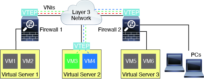
The underlying IP network between VTEPs is independent of the VXLAN overlay. Encapsulated packets are routed based on the outer IP address header, which has the initiating VTEP as the source IP address and the terminating VTEP as the destination IP address. For VXLAN encapsulation: The destination IP address can be a multicast group when the remote VTEP is not known. With Geneve, the ASA only supports static peers. The destination port for VXLAN is UDP port 4789 by default (user configurable). The destination port for Geneve is 6081.

VTEP Source Interface

The VTEP source interface is a regular ASA interface (physical, EtherChannel, or even VLAN) with which you plan to associate all VNI interfaces. You can configure one VTEP source interface per ASA/security context. Because you can only configure one VTEP source interface, you cannot configure both VXLAN and Geneve interfaces on the same device.There is an exception for ASA virtual clustering on AWS, where you can have two VTEP source interfaces: a VXLAN interface is used for the cluster control link, and a Geneve interface can be used for the Gateway Load Balancer.

The VTEP source interface can be devoted wholly to VXLAN traffic, although it is not restricted to that use. If desired, you can use the interface for regular traffic and apply a security policy to the interface for that traffic. For VXLAN traffic, however, all security policy must be applied to the VNI interfaces. The VTEP interface serves as a physical port only.

In transparent firewall mode, the VTEP source interface is not part of a BVI, and you do configure an IP address for it, similar to the way the management interface is treated.

VNI Interfaces

VNI interfaces are similar to VLAN interfaces: they are virtual interfaces that keep network traffic separated on a given physical interface by using tagging. You apply your security policy directly to each VNI interface.

You can only add one VTEP interface, and all VNI interfaces are associated with the same VTEP interface. There is an exception for ASA virtual clustering on AWS. For AWS clustering, you can have two VTEP source interfaces: a VXLAN interface is used for the cluster control link, and a Geneve interface can be used for the AWS Gateway Load Balancer.

VXLAN Packet Processing

VXLAN

Traffic entering and exiting the VTEP source interface is subject to VXLAN processing, specifically encapsulation or decapsulation.

Encapsulation processing includes the following tasks:

  • The VTEP source interface encapsulates the inner MAC frame with the VXLAN header.

  • The UDP checksum field is set to zero.

  • The Outer frame source IP is set to the VTEP interface IP.

  • The Outer frame destination IP is decided by a remote VTEP IP lookup.

Decapsulation; the ASA only decapsulates a VXLAN packet if:

  • It is a UDP packet with the destination port set to 4789 (this value is user configurable).

  • The ingress interface is the VTEP source interface.

  • The ingress interface IP address is the same as the destination IP address.

  • The VXLAN packet format is compliant with the standard.

Geneve

Traffic entering and exiting the VTEP source interface is subject to Geneve processing, specifically encapsulation or decapsulation.

Encapsulation processing includes the following tasks:

  • The VTEP source interface encapsulates the inner MAC frame with the Geneve header.

  • The UDP checksum field is set to zero.

  • The Outer frame source IP is set to the VTEP interface IP.

  • The Outer frame destination IP is set the peer IP address that you configured.

Decapsulation; the ASA only decapsulates a Geneve packet if:

  • It is a UDP packet with the destination port set to 6081 (this value is user configurable).

  • The ingress interface is the VTEP source interface.

  • The ingress interface IP address is the same as the destination IP address.

  • The Geneve packet format is compliant with the standard.

Peer VTEP

When the ASA sends a packet to a device behind a peer VTEP, the ASA needs two important pieces of information:

  • The destination MAC address of the remote device

  • The destination IP address of the peer VTEP

The ASA maintains a mapping of destination MAC addresses to remote VTEP IP addresses for the VNI interfaces.

VXLAN Peer

There are two ways in which the ASA can find this information:

  • A single peer VTEP IP address can be statically configured on the ASA.

    You cannot manually define multiple peers.

    The ASA then sends a VXLAN-encapsulated ARP broadcast to the VTEP to learn the end node MAC address.

  • A multicast group can be configured on each VNI interface (or on the VTEP as a whole).


    Note


    This option is not supported with Geneve.


    The ASA sends a VXLAN-encapsulated ARP broadcast packet within an IP multicast packet through the VTEP source interface. The response to this ARP request enables the ASA to learn both the remote VTEP IP address along with the destination MAC address of the remote end node.

Geneve Peer

The ASA virtual only supports statically defined peers. You can define the ASA virtual peer IP address on the AWS Gateway Load Balancer. Because the ASA virtual never initiates traffic to the Gateway Load Balancer, you do not also have to specify the Gateway Load Balancer IP address on the ASA virtual; it learns the peer IP address when it receives Geneve traffic. Multicast groups are not supported with Geneve.

VXLAN Use Cases

This section describes the use cases for implementing VXLAN on the ASA.

VXLAN Bridge or Gateway Overview

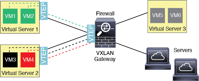
Each ASA VTEP acts as a bridge or gateway between end nodes such as VMs, servers, and PCs and the VXLAN overlay network. For incoming frames received with VXLAN encapsulation over the VTEP source interface, the ASA strips out the VXLAN header and forwards it to a physical interface connected to a non-VXLAN network based on the destination MAC address of the inner Ethernet frame.

The ASA always processes VXLAN packets; it does not just forward VXLAN packets untouched between two other VTEPs.
VXLAN Bridge

When you use a bridge group (transparent firewall mode, or optionally routed mode), the ASA can serve as a VXLAN bridge between a (remote) VXLAN segment and a local segment where both are in the same network. In this case, one member of the bridge group is a regular interface while the other member is a VNI interface.

VXLAN Gateway (Routed Mode)

The ASA can serve as a router between VXLAN and non-VXLAN domains, connecting devices on different networks.

Router Between VXLAN Domains

With a VXLAN-stretched Layer 2 domain, a VM can point to an ASA as its gateway while the ASA is not on the same rack, or even when the ASA is far away over the Layer 3 network.
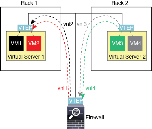
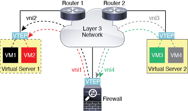
See the following notes about this scenario:

  1. For packets from VM3 to VM1, the destination MAC address is the ASA MAC address, because the ASA is the default gateway.

  2. The VTEP source interface on Virtual Server 2 receives packets from VM3, then encapsulates the packets with VNI 3’s VXLAN tag and sends them to the ASA.

  3. When the ASA receives the packets, it decapsulates the packets to get the inner frames.

  4. The ASA uses the inner frames for route lookup, then finds that the destination is on VNI 2. If it does not already have a mapping for VM1, the ASA sends an encapsulated ARP broadcast on the multicast group IP on VNI 2.


    Note


    The ASA must use dynamic VTEP peer discovery because it has multiple VTEP peers in this scenario.


  5. The ASA encapsulates the packets again with the VXLAN tag for VNI 2 and sends the packets to Virtual Server 1. Before encapsulation, the ASA changes the inner frame destination MAC address to be the MAC of VM1 (multicast-encapsulated ARP might be needed for the ASA to learn the VM1 MAC address).

  6. When Virtual Server 1 receives the VXLAN packets, it decapsulates the packets and delivers the inner frames to VM1.

AWS Gateway Load Balancer and Geneve Single-Arm Proxy


Note


This use case is the only currently supported use case for Geneve interfaces.


The AWS Gateway Load Balancer combines a transparent network gateway and a load balancer that distributes traffic and scales virtual appliances on demand. The ASA virtual supports the Gateway Load Balancer centralized control plane with a distributed data plane (Gateway Load Balancer endpoint). The following figure shows traffic forwarded to the Gateway Load Balancer from the Gateway Load Balancer endpoint. The Gateway Load Balancer balances traffic among multiple ASA virtuals, which inspect the traffic before either dropping it or sending it back to the Gateway Load Balancer (U-turn traffic). The Gateway Load Balancer then sends the traffic back to the Gateway Load Balancer endpoint and to the destination.
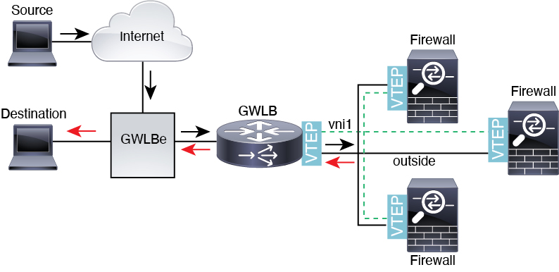
Figure 1. Geneve Single-Arm Proxy

Azure Gateway Load Balancer and Paired Proxy

In an Azure service chain, ASA virtuals act as a transparent gateway that can intercept packets between the internet and the customer service. The ASA virtual defines an external interface and an internal interface on a single NIC by utilizing VXLAN segments in a paired proxy.

The following figure shows traffic forwarded to the Azure Gateway Load Balancer from the Public Gateway Load Balancer on the external VXLAN segment. The Gateway Load Balancer balances traffic among multiple ASA virtuals, which inspect the traffic before either dropping it or sending it back to the Gateway Load Balancer on the internal VXLAN segment. The Azure Gateway Load Balancer then sends the traffic back to the Public Gateway Load Balancer and to the destination.
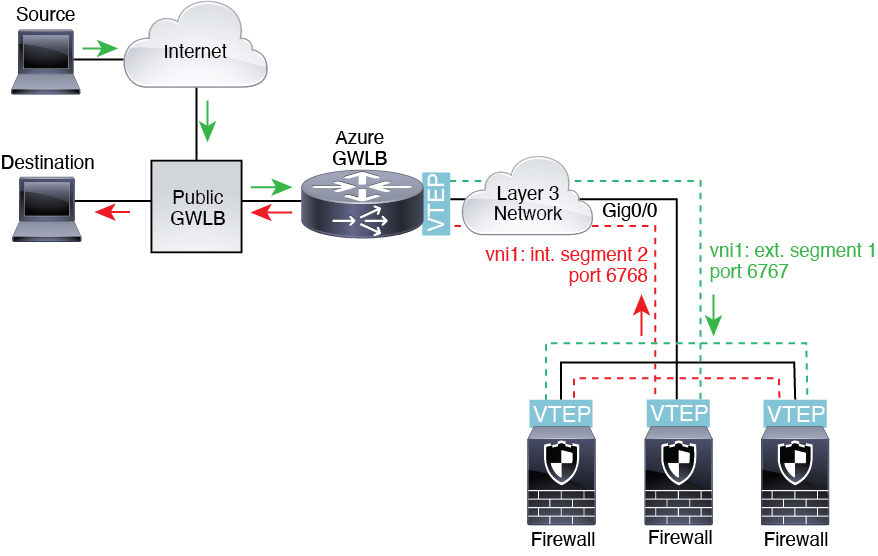
Figure 2. Azure Gateway Load Balancer with Paired Proxy
Azure Gateway Load Balancer with Paired Proxy

Requirements and Prerequisites for VXLAN Interfaces

Model Requirements

  • Firepower 1010 switch ports and VLAN interfaces are not supported as VTEP interfaces.

  • Geneve encapsulation is supported for the following models: ASAv30, ASAv50, ASAv100 on Amazon Web Services (AWS)

  • VXLAN in paired proxy mode is supported for the following models:

    • ASA virtual in Azure

Guidelines for VXLAN Interfaces

Firewall Mode

  • Geneve interfaces are only supported in routed firewall mode.

  • Paired proxy VXLAN interfaces are only supported in routed firewall mode.

IPv6

  • The VNI interface supports both IPv4 and IPv6 traffic.

  • The VTEP source interface IP address only supports IPv4.

Clustering and Multiple Context Mode

  • ASA clustering does not support VXLAN in Individual Interface mode except for the cluster control link (ASA virtual only). Only Spanned EtherChannel mode supports VXLAN.

    An exception is made for the ASA virtualon AWS, which can use an additional Geneve interface for use with the GWLB.

  • Geneve interfaces are only supported in single context mode. They are not supported with multiple context mode.

Routing

  • Only static routing or Policy Based Routing is supported on the VNI interface; dynamic routing protocols are not supported.

MTU

  • VXLAN encapsulation—If the source interface MTU is less than 1554 bytes, then the ASA automatically raises the MTU. In this case, the entire Ethernet datagram is being encapsulated, so the new packet is larger and requires a larger MTU. If the MTU used by other devices is larger, then you should set the source interface MTU to be the network MTU + 54 bytes. This MTU requires you to enable jumbo frame reservation on some models; see Enable Jumbo Frame Support (ASA Virtual, ISA 3000).

  • Geneve encapsulation—If the source interface MTU is less than 1806 bytes, then the ASA automatically raises the MTU to 1806 bytes. In this case, the entire Ethernet datagram is being encapsulated, so the new packet is larger and requires a larger MTU. If the MTU used by other devices is larger, then you should set the source interface MTU to be the network MTU + 306 bytes. This MTU requires you to enable jumbo frame reservation on some models; see Enable Jumbo Frame Support (ASA Virtual, ISA 3000).

Default Settings for VXLAN Interfaces

VNI interfaces are enabled by default.

Configure VXLAN Interfaces

To configure VXLAN, perform the following steps.


Note


You can configure either VXLAN or Geneve (ASA virtual only). For Geneve interfaces, see Configure Geneve Interfaces.


Procedure


Step 1

Configure the VTEP Source Interface.

Step 2

Configure the VNI Interface

Step 3

(Optional) Change the VXLAN UDP Port.

Step 4

(Azure GWLB) Allow Gateway Load Balancer Health Checks.


Configure the VTEP Source Interface

You can configure one VTEP source interface per ASA or per security context. The VTEP is defined as a Network Virtualization Endpoint (NVE).

Before you begin

For multiple context mode, complete the tasks in this section in the context execution space. Enter the changeto context name command to change to the context you want to configure.

Procedure


Step 1

(Transparent mode) Specify that the source interface is NVE-only:

interface id   

nve-only

Example:


ciscoasa(config)# interface gigabitethernet 1/1
ciscoasa(config-if)# nve-only

This setting lets you configure an IP address for the interface. This command is optional for routed mode where this setting restricts traffic to VXLAN and common management traffic only on this interface.

Step 2

Configure the source interface name and IPv4 address.

Example:

(Routed Mode)


ciscoasa(config)# interface gigabitethernet 1/1
ciscoasa(config-if)# nameif outside
ciscoasa(config-if)# ip address 10.1.1.1 255.255.255.0


Example:

(Transparent Mode)


ciscoasa(config)# interface gigabitethernet 1/1
ciscoasa(config-if)# nve-only
ciscoasa(config-if)# nameif outside
ciscoasa(config-if)# ip address 10.1.1.1 255.255.255.0


Step 3

Specify the NVE instance:

nve 1

You can only specify one NVE instance, with the ID 1.

Example:


ciscoasa(config)# nve 1
ciscoasa(cfg-nve)#

Step 4

Specify VXLAN encapsulation.

encapsulation vxlan

Example:


ciscoasa(cfg-nve)# encapsulation vxlan

Step 5

Specify the source interface name that you configured in Step 2:

source-interface interface-name

Example:


ciscoasa(cfg-nve)# source-interface outside

Note


If the VTEP interface MTU is less than 1554 bytes, then the ASA automatically raises the MTU to 1554 bytes.

Step 6

(Multiple context mode; Optional for single mode) Manually specify the peer VTEP IP address:

peer ip ip_address

Example:


ciscoasa(cfg-nve)# peer ip 10.1.1.2

If you specify the peer IP address, you cannot use multicast group discovery. Multicast is not supported in multiple context mode, so manual configuration is the only option. You can only specify one peer for the VTEP.

Step 7

(Optional; single mode only) Specify a default multicast group for all associated VNI interfaces:

default-mcast-group mcast_ip

Example:


ciscoasa(cfg-nve)# default-mcast-group 236.0.0.100

If you do not configure the multicast group per VNI interface, then this group is used. If you configure a group at the VNI interface level, then that group overrides this setting.


Configure the VNI Interface

Add a VNI interface, associate it with the VTEP source interface, and configure basic interface parameters.

For the ASA virtual in Azure, you can configure either a regular VXLAN interface, or you can configure a paired proxy mode VXLAN interface for use with the Azure GWLB.

Procedure


Step 1

Create the VNI interface:

interface vni vni_num

Example:


ciscoasa(config)# interface vni 1

Set the ID between 1 and 10000. This ID is only an internal interface identifier.

Step 2

(Regular VXLAN) Specify the VXLAN segment ID:

segment-id id

Example:


ciscoasa(config-if)# segment-id 1000

Set the ID between 1 and 16777215. The segment ID is used for VXLAN tagging.

Step 3

(Paired Proxy VXLAN for Azure GWLB) Enable proxy paired mode and set the required parameters.

  1. Enable proxy paired mode.

    proxy paired

    Example:

    
    ciscoasa(config-if)# proxy paired
    
    
  2. Set the internal port.

    internal-port port_number

    Where the port_number is between 1024 and 65535.

    Example:

    
    ciscoasa(config-if)# internal-port 2000
    
    
  3. Set the internal segment ID.

    internal-segment-id id_number

    Where the id_number is between 1 and 16777215.

    Example:

    
    ciscoasa(config-if)# internal-segment-id 101
    
    
  4. Set the external port.

    external-port port_number

    Where the port_number is between 1024 and 65535.

    Example:

    
    ciscoasa(config-if)# external-port 2001
    
    
  5. Set the external segment ID.

    external-segment-id id_number

    Where the id_number is between 1 and 16777215.

    Example:

    
    ciscoasa(config-if)# external-segment-id 102
    
    
  6. Allow traffic to enter and exit the same interface.

    same-security-traffic permit intra-interface

    Example:

    
    ciscoasa(config)# same-security-traffic permit intra-interface


Step 4

(Required for transparent mode) Specify the bridge group to which you want to associate this interface:

bridge-group number

Example:


ciscoasa(config-if)# bridge-group 1

See Configure Bridge Group Interfaces to configure the BVI interface and associate regular interfaces to this bridge group.

Step 5

Associate this interface with the VTEP source interface:

vtep-nve 1

Step 6

Name the interface:

nameif vni_interface_name

Example:


ciscoasa(config-if)# nameif vxlan1000

The name is a text string up to 48 characters, and is not case-sensitive. You can change the name by reentering this command with a new value. Do not enter the no form, because that command causes all commands that refer to that name to be deleted.

Step 7

(Routed mode) Assign an IPv4 and/or IPv6 address:

ip address {ip_address [mask] [standby ip_address] | dhcp [setroute] | pppoe [setroute]}

ipv6 address {autoconfig | ipv6-address/prefix-length [standby ipv6-address]}

Example:


ciscoasa(config-if)# ip address 192.168.1.1 255.255.255.0 standby 192.168.1.2
ciscoasa(config-if)# ipv6 address 2001:0DB8::BA98:0:3210/48

Step 8

Set the security level:

security-level level

Example:


ciscoasa(config-if)# security-level 50

Where number is an integer between 0 (lowest) and 100 (highest).

Step 9

(Single mode) Set the multicast group address:

mcast-group multicast_ip

Example:


ciscoasa(config-if)# mcast-group 236.0.0.100

If you do not set the multicast group for the VNI interface, the default group from the VTEP source interface configuration is used, if available. If you manually set a VTEP peer IP for the VTEP source interface, you cannot specify a multicast group for the VNI interface. Multicast is not supported in multiple context mode.


(Optional) Change the VXLAN UDP Port

By default, the VTEP source interface accepts VXLAN traffic to UDP port 4789. If your network uses a non-standard port, you can change it.

Before you begin

For multiple context mode, complete this task in the system execution space. To change from the context to the system execution space, enter the changeto system command.

Procedure


Set the VXLAN UDP port:

vxlan port number

Example:


ciscoasa(config)# vxlan port 5678


Configure Geneve Interfaces

To configure Geneve interfaces for the ASA virtual, perform the following steps.


Note


You can configure either VXLAN or Geneve. For VXLAN interfaces, see Configure VXLAN Interfaces.


Procedure


Step 1

Configure the VTEP Source Interface for Geneve.

Step 2

Configure the VNI Interface for Geneve

Step 3

Allow Gateway Load Balancer Health Checks.


Configure the VTEP Source Interface for Geneve

You can configure one VTEP source interface per ASA virtual. The VTEP is defined as a Network Virtualization Endpoint (NVE).

Procedure


Step 1

(Optional) Specify that the source interface is NVE-only.

interface id   

nve-only

Example:


ciscoasa(config)# interface gigabitethernet 1/1
ciscoasa(config-if)# nve-only

This setting restricts traffic to VXLAN and common management traffic only on this interface.

Step 2

Configure the source interface name and IPv4 address.

Example:


ciscoasa(config)# interface gigabitethernet 1/1
ciscoasa(config-if)# nameif outside
ciscoasa(config-if)# ip address 10.1.1.1 255.255.255.0

Step 3

Specify the NVE instance:

nve 1

You can only specify one NVE instance, with the ID 1.

Example:


ciscoasa(config)# nve 1
ciscoasa(cfg-nve)#

Step 4

Specify Geneve encapsulation.

encapsulation geneve

Do not change the Geneve port; AWS requires a port of 6081.

Example:


ciscoasa(cfg-nve)# encapsulation geneve

Step 5

Specify the source interface name that you configured in Step 2:

source-interface interface-name

Example:


ciscoasa(cfg-nve)# source-interface outside

Note


If the source interface MTU is less than 1806 bytes, then the ASA automatically raises the MTU to 1806 bytes.


Configure the VNI Interface for Geneve

Add a VNI interface, associate it with the VTEP source interface, and configure basic interface parameters.

Procedure


Step 1

Create the VNI interface:

interface vni vni_num

Example:


ciscoasa(config)# interface vni 1

Set the ID between 1 and 10000. This ID is only an internal interface identifier.

Step 2

Associate this interface with the VTEP source interface:

vtep-nve 1

Step 3

Name the interface:

nameif vni_interface_name

Example:


ciscoasa(config-if)# nameif geneve1000

The name is a text string up to 48 characters, and is not case-sensitive. You can change the name by reentering this command with a new value. Do not enter the no form, because that command causes all commands that refer to that name to be deleted.

Step 4

Assign an IPv4 and/or IPv6 address:

ip address {ip_address [mask] [standby ip_address]}

ipv6 address {autoconfig | ipv6-address/prefix-length [standby ipv6-address]}

Geneve only supports a static IP address.

Example:


ciscoasa(config-if)# ip address 192.168.1.1 255.255.255.0 standby 192.168.1.2
ciscoasa(config-if)# ipv6 address 2001:0DB8::BA98:0:3210/48

Step 5

Set the security level:

security-level level

Where level is an integer between 0 (lowest) and 100 (highest).

Example:


ciscoasa(config-if)# security-level 50

Step 6

Enable single-arm proxy.

proxy single-arm

Example:


ciscoasa(config-if)# proxy single-arm

Step 7

Allow traffic to enter and exit the same interface.

same-security-traffic permit intra-interface

Example:


ciscoasa(config)# same-security-traffic permit intra-interface


Allow Gateway Load Balancer Health Checks

The AWS or Azure Gateway Load Balancer requires appliances to answer a health check properly. The AWS Gateway Load Balancer will only send traffic to appliances that are considered healthy.

You must configure the ASA virtual to respond to an SSH, Telnet, HTTP, or HTTPS health check.

SSH Connection

For SSH, allow SSH from the Gateway Load Balancer. The Gateway Load Balancer will attempt to establish a connection to the ASA virtual, and the ASA virtual's prompt to log in is taken as proof of health.


Note


An SSH login attempt will time out after 1 minute. You will need to configure a longer health check interval on the Gateway Load Balancer to accommodate this timeout.


Example


! Allow SSH connections from GWLB network: 10.0.1.0/24
ssh 10.0.1.0 255.255.255.0 outside

Telnet Connection

For Telnet, allow Telnet from the Gateway Load Balancer. The Gateway Load Balancer will attempt to establish a connection to the ASA virtual, and the ASA virtual's prompt to log in is taken as proof of health.


Note


You cannot Telnet to the lowest security level interface, so this method may not be practical.


Example


! Allow Telnet connections from GWLB network: 10.0.1.0/24
telnet 10.0.1.0 255.255.255.0 outside

HTTP(S) Cut-Through Proxy

You can configure the ASA to prompt the Gateway Load Balancer for an HTTP(S) login.

Example


! Identify health probe HTTP traffic from GWLB nw 10.0.1.0/24 to ASAv interface 10.2.2.2
access-list gwlb extended permit tcp 10.0.1.0 255.255.255.0 host 10.2.2.2 eq www
! Enable HTTP authentication
aaa authentication http console LOCAL
! Require authentication for the health probe traffic
aaa authentication match gwlb outside LOCAL
! Use an HTTP login page on the ASA
aaa authentication listener http outside port www

HTTP(S) Redirection Using Static Interface NAT with Port Translation

You can configure the ASA virtual to redirect health checks to a metadata HTTP(S) server. For HTTP(S) health checks, the HTTP(S) server must reply to the Gateway Load Balancer with a status code in the range 200 to 399. Because the ASA virtual has limits on the the number of simultaneous management connections, you may choose to offload the health check to an external server.

Static interface NAT with port translation lets you redirect a connection to a port (such as port 80) to a different IP address. For example, translate an HTTP packet from the Gateway Load Balancer with a destination of the ASA virtual outside interface so that it appears to be from the ASA virtual outside interface with a destination of the HTTP server. The ASA virtual then forwards the packet to the mapped destination address. The HTTP server responds to the ASA virtual outside interface, and then the ASA virtual forwards the response back to the Gateway Load Balancer. You need an access rule that allows traffic from the Gateway Load Balancer to the HTTP server.

Example


! Permit HTTP traffic from GWLB nw 10.0.1.0/24 to HTTP server 10.2.2.3
access-list gwlb-health extended permit tcp 10.0.1.0 255.255.255.0 host 10.2.2.3 eq www
access-group gwlb-health in interface outside

! Create network objects
object network gwlb-subnet
 subnet 10.0.1.0 255.255.255.0
object-group network gwlb
    network-object object gwlb-subnet
object-group network http-server
    network-object host 10.2.2.3
object service http80
    service tcp destination eq www

! For HTTP, translate src GWLB IP to outside IP; translate dest of outside IP to HTTP Server IP
nat (outside,outside) source static gwlb interface destination static interface http-server service http80 http80

Monitoring VXLAN Interfaces

See the following commands to monitor VTEP and VNI interfaces.

  • show nve [id] [summary]

    This command shows the parameters, status and statistics of a NVE interface, status of its carrier interface (source-interface), IP address of the carrier interface, VNIs that use this NVE as the VXLAN VTEP, and peer VTEP IP addresses associated with this NVE interface. With the summary option, this command only shows the status of the NVE interface, number of VNIs behind the NVE interface, and number of VTEPs discovered.

    See the following output for the show nve 1 command:

    
    ciscoasa# show nve 1
    ciscoasa(config-if)# show nve
    nve 1, source-interface "inside" is up
    IP address 15.1.2.1, subnet mask 255.255.255.0
    Encapsulation: vxlan
    Encapsulated traffic statistics:
    6701004 packets input, 3196266002 bytes
    6700897 packets output, 3437418084 bytes
    1 packets dropped
    Number of configured static peer VTEPs: 0
    Number of discovered peer VTEPs: 1
    Discovered peer VTEPs:
    IP address 15.1.2.3
    Number of VNIs attached to nve 1: 2
    VNIs attached:
    vni 2: segment-id 5002, mcast-group 239.1.2.3
    vni 1: segment-id 5001, mcast-group 239.1.2.3


    See the following output for the show nve 1 summary command:

    
    ciscoasa# show nve 1 summary
    nve 1, source-interface "inside" is up
    Encapsulation: vxlan
    Number of configured static peer VTEPs: 0
    Number of discovered peer VTEPs: 1
    Default multicast group: 239.1.2.3
    Number of VNIs attached to nve 1: 2
    
    
  • show interface vni id [summary]

    This command shows the parameters, status and statistics of a VNI interface, status of its bridged interface (if configured), and NVE interface it is associated with. The summary option shows only the VNI interface parameters.

    See the following output for the show interface vni 1 command:

    
    ciscoasa# show interface vni 1
    Interface vni1 "vni-inside", is up, line protocol is up
    VTEP-NVE 1
    Segment-id 5001
    Tag-switching: disabled
    MTU: 1500
    MAC: aaaa.bbbb.1234
    IP address 192.168.0.1, subnet mask 255.255.255.0
    Multicast group 239.1.3.3
    Traffic Statistics for "vni-inside":
    235 packets input, 23606 bytes
    524 packets output, 32364 bytes
    14 packets dropped
    1 minute input rate 0 pkts/sec, 0 bytes/sec
    1 minute output rate 0 pkts/sec, 2 bytes/sec
    1 minute drop rate, 0 pkts/sec
    5 minute input rate 0 pkts/sec, 0 bytes/sec
    5 minute output rate 0 pkts/sec, 0 bytes/sec
    5 minute drop rate, 0 pkts/sec


    See the following output for the show interface vni 1 summary command:

    
    ciscoasa# show interface vni 1 summary
    Interface vni1 "vni-inside", is up, line protocol is up
    VTEP-NVE 1
    Segment-id 5001
    Tag-switching: disabled
    MTU: 1500
    MAC: aaaa.bbbb.1234
    IP address 192.168.0.1, subnet mask 255.255.255.0
    Multicast group not configured
    
    
  • show vni vlan-mapping

    This command shows the mapping between VNI segment IDs and VLAN interfaces or physical interfaces. This command is only valid in transparent firewall mode because in routed mode, the mapping between VXLANs and VLANs can include too many values to show.

    See the following output for the show vni vlan-mapping command:

    
    ciscoasa# show vni vlan-mapping
    vni1: segment-id: 6000, interface: 'g0110', vlan 10, interface: 'g0111', vlan 11
    vni2: segment_id: 5000, interface: 'g01100', vlan 1, interface: 'g111', vlan 3, interface: 'g112', vlan 4
    
    
  • show arp vtep-mapping

    This command displays MAC addresses cached on the VNI interface for IP addresses located in the remote segment domain and the remote VTEP IP addresses.

    See the following output for the show arp vtep-mapping command:

    
    ciscoasa# show arp vtep-mapping
    vni-outside 192.168.1.4 0012.0100.0003 577 15.1.2.3
    vni-inside 192.168.0.4 0014.0100.0003 577 15.1.2.3
    
    
  • show mac-address-table vtep-mapping

    This command displays the Layer 2 forwarding table (MAC address table) on the VNI interface with the remote VTEP IP addresses.

    See the following output for the show mac-address-table vtep-mapping command:

    
    ciscoasa# show mac-address-table vtep-mapping
    interface                   mac  address       type	    Age(min)   bridge-group    VTEP
    ------------------------------------------------------------------------------------------------
    vni-outside                00ff.9200.0000      dynamic      5         1      		10.9.1.3
    vni-inside                 0041.9f00.0000      dynamic      5         1      10.9.1.3


Examples for VXLAN Interfaces

See the following configuration examples for VXLAN.

Transparent VXLAN Gateway Example

See the following description of this example:

  • The outside interface on GigabitEthernet 0/0 is used as the VTEP source interface, and it is connected to the Layer 3 network.

  • The insidevm100 VLAN subinterface on GigabitEthernet 0/1.100 is connected to the 10.10.10.0/24 network, on which VM3 resides. When VM3 communicates with VM1 (not shown; both have 10.10.10.0/24 IP addresses), the ASA uses VXLAN tag 6000.

  • The insidevm200 VLAN subinterface on GigabitEthernet 0/1.200 is connected to the 10.20.20.0/24 network, on which VM2 resides. When VM2 communicates with VM4 (not shown; both have 10.20.20.0/24 IP addresses), the ASA uses VXLAN tag 8000.

  • The insidepc interface on GigabitEthernet 0/2 is connected to the 10.30.30.0/24 network on which a few PCs reside. When those PCs communicate with VMs/PCs (not shown) behind a remote VTEP that belongs to same network (all have 10.30.30.0/24 IP addresses), the ASA uses VXLAN tag 10000.

ASA Configuration


firewall transparent
vxlan port 8427
!
interface gigabitethernet0/0
  nve-only
  nameif outside
  ip address 192.168.1.30 255.255.255.0
  no shutdown
!
nve 1
  encapsulation vxlan
  source-interface outside
!
interface vni1
  segment-id 6000
  nameif vxlan6000
  security-level 0
  bridge-group 1
  vtep-nve 1
  mcast-group 235.0.0.100
!
interface vni2
  segment-id 8000
  nameif vxlan8000
  security-level 0
  bridge-group 2
  vtep-nve 1
  mcast-group 236.0.0.100
!
interface vni3
  segment-id 10000
  nameif vxlan10000
  security-level 0
  bridge-group 3
  vtep-nve 1
  mcast-group 236.0.0.100
!
interface gigabitethernet0/1.100
  nameif insidevm100
  security-level 100
  bridge-group 1
!
interface gigabitethernet0/1.200
  nameif insidevm200
  security-level 100
  bridge-group 2
!
interface gigabitethernet0/2
  nameif insidepc
  security-level 100
  bridge-group 3
!
interface bvi 1
  ip address 10.10.10.1 255.255.255.0
!
interface bvi 2
  ip address 10.20.20.1 255.255.255.0
!
interface bvi 3
  ip address 10.30.30.1 255.255.255.0

Notes

  • For VNI interfaces vni1 and vni2, the inner VLAN tag is removed during encapsulation.

  • VNI interfaces vni2 and vni3 share the same multicast IP address for encapsulated ARP over multicast. This sharing is allowed.

  • The ASA bridges the VXLAN traffic to non-VXLAN-supported interfaces based on the above BVIs and bridge group configurations. For each of the stretched Layer 2 network segments (10.10.10.0/24, 10.20.20.0/24 and 10.30.30.0/24), the ASA serves as a bridge.

  • It is allowed to have more than one VNI or more than one regular interface (VLAN or just physical interface) in a bridge group. The forwarding or association between VXLAN segment ID to the VLAN ID (or a physical interface) is decided by the destination MAC address and which interface connects to the destination.

  • The VTEP source-interface is a Layer 3 interface in transparent firewall mode indicated by nve-only in the interface configuration. The VTEP source interface is not a BVI interface or a management interface, but it has an IP address and uses the routing table.

VXLAN Routing Example

See the following description of this example:

  • VM1 (10.10.10.10) is hosted on Virtual Server 1, and VM2 (10.20.20.20) is hosted on Virtual Server 2.

  • The default gateway for VM1 is the ASA, which is not in the same pod as Virtual Server 1, but VM1 is not aware of it. VM1 only knows that its default gateway IP address is 10.10.10.1. Similarly, VM2 only knows that its default gateway IP address is 10.20.20.1.

  • The VTEP-supported hypervisors on Virtual Server 1 and 2 are able to communicate with the ASA over the same subnet or through a Layer 3 network (not shown; in which case, the ASA and uplinks of virtual servers have different network addresses).

  • VM1’s packet will be encapsulated by its hypervisor’s VTEP and sent to its default gateway over VXLAN tunneling.

  • When VM1 sends a packet to VM2, the packet will be sent through default gateway 10.10.10.1 from its perspective. Virtual Server1 knows 10.10.10.1 is not local, so the VTEP encapsulates the packet over VXLAN and sends it to ASA’s VTEP.

  • On the ASA, the packet is decapsulated. The VXLAN segment ID is learned during decapsulation. The ASA then re-injects the inner frame to the corresponding VNI interface (vni1) based on the VXLAN segment ID. The ASA then conducts a route lookup and sends the inner packet through another VNI interface, vni2. All egressing packets through vni2 are encapsulated with VXLAN segment 8000 and sent through the VTEP to outside.

  • Eventually the encapsulated packet is received by the VTEP of Virtual Server 2, which decapsulates it and forwards it to VM2.

ASA Configuration


interface gigabitethernet0/0
  nameif outside
  ip address 192.168.1.30 255.255.255.0
  no shutdown
!
nve 1
  encapsulation vxlan
  source-interface outside
  default-mcast-group 235.0.0.100
!
interface vni1
  segment-id 6000
  nameif vxlan6000
  security-level 0
  vtep-nve 1
  ip address 10.20.20.1 255.255.255.0
!
interface vni2
  segment-id 8000
  nameif vxlan8000
  security-level 0
  vtep-nve 1
  ip address 10.10.10.1 255.255.255.0
!

History for VXLAN Interfaces

Table 1. History for VXLAN Interfaces

Feature Name

Releases

Feature Information

Paired proxy VXLAN for the ASA virtual for the Azure Gateway Load Balancer

9.19(1)

You can configure a paired proxy mode VXLAN interface for the ASA virtual in Azure for use with the Azure Gateway Load Balancer (GWLB). The ASA virtual defines an external interface and an internal interface on a single NIC by utilizing VXLAN segments in a paired proxy.

New/Modified commands: external-port, external-segment-id, internal-port, internal-segment-id, proxy paired

Geneve support for the ASA virtual on AWS for the AWS Gateway Load Balancer

9.17(1)

Geneve encapsulation support was added for the ASAv30, ASAv50, and ASAv100 to support single-arm proxy for the AWS Gateway Load Balancer.

New/Modified commands: debug geneve, debug nve, debug vxlan, encapsulation, packet-tracer geneve, proxy single-arm, show asp drop, show capture, show interface, show nve,

VXLAN support

9.4(1)

VXLAN support was added, including VXLAN tunnel endpoint (VTEP) support. You can define one VTEP source interface per ASA or security context.

We introduced the following commands: debug vxlan, default-mcast-group, encapsulation vxlan, inspect vxlan, interface vni, mcast-group, nve, nve-only, peer ip, segment-id, show arp vtep-mapping, show interface vni, show mac-address-table vtep-mapping, show nve, show vni vlan-mapping, source-interface, vtep-nve, vxlan port