Prepare for Installation

General Site Requirements


Warning


Statement 1005—Circuit Breaker

This product relies on the building's installation for short-circuit (overcurrent) protection. Ensure that the protective device is rated not greater than: 20A (AC).


Warning


Statement 1017—Restricted Area

This unit is intended for installation in restricted access areas. Only skilled, instructed, or qualified personnel can access a restricted access area.


Warning


Statement 1022—Disconnect Device

To reduce the risk of electric shock and fire, a readily accessible disconnect device must be incorporated in the fixed wiring.


Warning


Statement 1047—Overheating Prevention

To reduce the risk of fire or bodily injury, do not operate the unit in an area that exceeds the maximum recommended ambient temperature of: 50 °C


Cautions and Regulatory Compliance Statements for NEBS

The NEBS-GR-1089-CORE regulatory compliance statements and requirements are discussed in this section.

Cautions and Regulatory Compliance Statements for NEBS

NEBS describes the environment of a typical United States Regional Bell Operating Company (RBOC) central office. NEBS is the most common set of safety, spatial, and environmental design standards applied to telecommunications equipment in the United States. It is not a legal or regulatory requirement, but rather an industry requirement.


Warning


Statement 7003—Telcordia GR-1089 NEBS Standard for Electromagnetic Compatibility and Safety

The intrabuilding port(s) of the equipment or subassembly must use shielded intrabuilding cabling/wiring that is grounded at both ends.

This statement applies to the intrabuilding ports listed below:

Gigabit Ethernet WAN port


Warning


Statement 7005—Intrabuilding Lightning Surge and AC Power Fault

The intrabuilding port(s) of the equipment or subassembly must not be metallically connected to interfaces that connect to the outside plant (OSP) or its wiring. These interfaces are designed for use as intrabuilding interfaces only (Type 2 or Type 4 ports as described in GR-1089-CORE) and require isolation from the exposed OSP cabling. The addition of primary protectors is not sufficient protection to connect these interfaces metallically to OSP wiring.

This statement applies to the intrabuilding ports listed below:

Gigabit Ethernet WAN port


Warning


Statement 7012—Equipment Interfacing with AC Power Ports

Connect this equipment to AC mains that are provided with a surge protective device (SPD) at the service equipment that complies with NFPA 70, the National Electrical Code (NEC).


Note


Statement 7013—Equipment Grounding Systems—Common Bonding Network (CBN)

This equipment is suitable for installations using the CBN.


Note


Statement 8015—Installation Location Network Telecommunications Facilities

This equipment is suitable for installation in network telecommunications facilities.


Note


Statement 8016—Installation Location Where the National Electric Code (NEC) Applies

This equipment is suitable for installation in locations where the NEC applies.


Note


These routers are designed to boot up in less than 30 minutes provided the neighboring devices are fully operational.


Safety Recommendations


Warning


Statement 9001—Product Disposal

Ultimate disposal of this product should be handled according to all national laws and regulations.


Warning


Statement 1071—Warning Definition

IMPORTANT SAFETY INSTRUCTIONS

Before you work on any equipment, be aware of the hazards involved with electrical circuitry and be familiar with standard practices for preventing accidents. Read the installation instructions before using, installing, or connecting the system to the power source. Use the statement number at the beginning of each warning statement to locate its translation in the translated safety warnings for this device.

SAVE THESE INSTRUCTIONS


Warning


To ensure compliance with exposure limits to radio frequency fields, the antenna(s) of CG522-E should be no closer than 20cms from the body during use.


Safety with Electricity


Warning


Statement 1028—More Than One Power Supply

This unit might have more than one power supply connection. To reduce risk of electric shock, remove all connections to de-energize the unit.


Warning


Statement 1089—Instructed and Skilled Person Definitions

An instructed person is someone who has been instructed and trained by a skilled person and takes the necessary precautions when working with equipment.

A skilled person or qualified personnel is someone who has training or experience in the equipment technology and understands potential hazards when working with equipment.

There are no serviceable parts inside. To avoid risk of electric shock, do not open.


Warning


Statement 1090—Installation by Skilled Person

Only a skilled person should be allowed to install, replace, or service this equipment. See statement 1089 for the definition of a skilled person.

There are no serviceable parts inside. To avoid risk of electric shock, do not open.


Install the SIM Cards

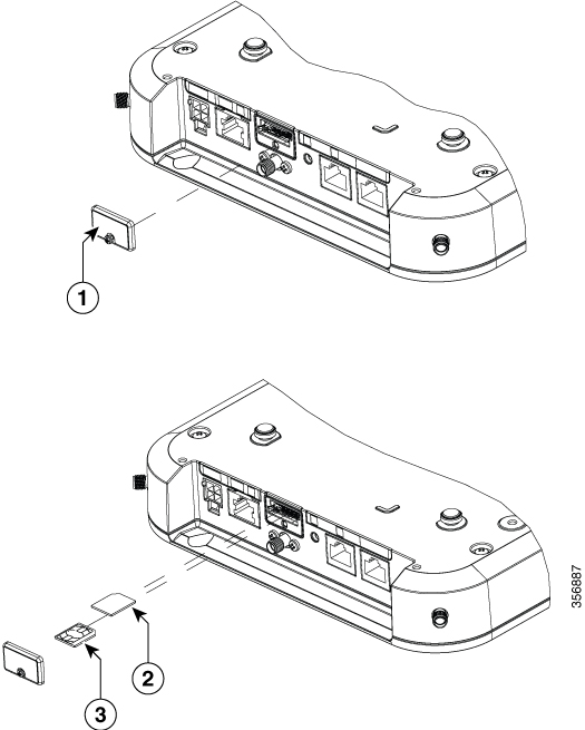
The SIM card socket is located on the side of the unit.

Figure 1. Removing SIM Cover and Installing a SIM

1

SIM-cover

2

SIM 0

3

SIM 1

The Cellular Gateway unit supports dual SIM cards behind a panel cover. To install SIM cards, follow these steps:

Procedure


Step 1

Loosen the screw on the SIM cover and remove the SIM cover assembly. (The screw is captive to the SIM cover and should not be removed from the SIM cover assembly)

Step 2

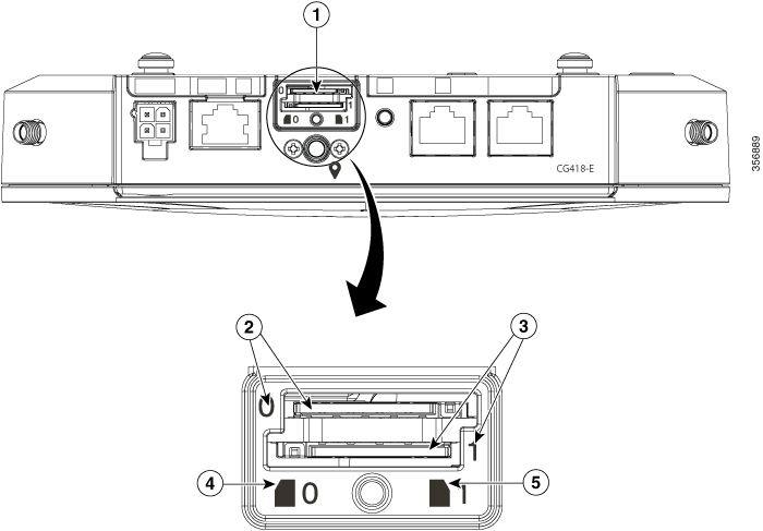
Install SIM0 or SIM1 in their respective slots. SIM location (0 or 1) is marked on both the SIM cover and unit panel face (visible if the SIM cover is removed). The SIM icons show the correct orientation required to install the SIM into each respective connector. SIM connectors are of push-push type. To install, insert the SIM card into the connector until you feel or hear it click, and let go. The SIM is locked in the connector. To remove the SIM card, depress the SIM in the connector slot again until you feel or hear a click and let it go. The SIM connector ejects part of the way from the connector. Hold and pull out the SIM card.

Step 3

After SIM cards are installed, replace the SIM cover and secure with a screw.

Note

 
We recommend that you use industrial-grade SIM cards.
Figure 2. Installing SIMs

1

SIM sockets

2

SIM0 slot

3

SIM1 slot

4

Orientation notch (SIM0)

5

Orientation notch (SIM1)


Attach the Antennae

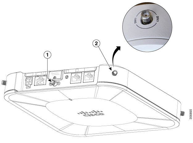
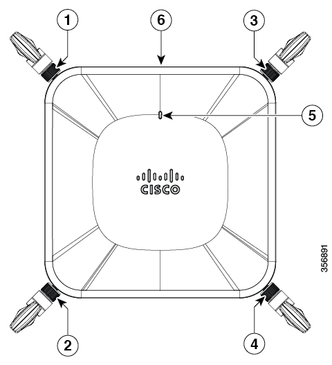
Figure 3. Antennae or GPS Connection

1

GPS: The GPS connection is on the I/O face (CG418-E only)

2

Antenna: The antenna connections are on each corner, one each on all four corners, and are labeled with the connection type.

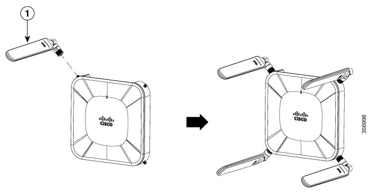
Figure 4. Dipole Antennae (5G-ANTM-SMA-D) Attachment and Location Designations

1

Four antennae attached on all four corners of the Cisco Catalyst Cellular Gateway unit


Note


You should remove the caps from the corner antennae connectors before installing the antennae to the cellular gateway unit.


Figure 5. Antennae Attachments

CG418-E

CG522-E

1

Antenna "PRI1"

Antenna "MIMO1"

2

Antenna "PRI0"

Antenna "MIMO2"

3

Antenna "DIV1"

Antenna "MAIN"

4

Antenna "DIV0"

Antenna "AUX"

5

LEDs (CG418-E shown above, CG522-E has 2 LEDs)

6

I/O surface (must face upwards for safety reasons)

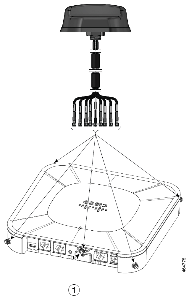
Figure 6. Attaching 5G NR Antenna (5G-ANTM-O4-B) to CG418-E and CG522-E

1

GPS Port

Note


This port connects on CG418-E only.


Note


5G NR Antenna (5G-ANTM-04-B) is supported on both CG418-E and CG522-E.


  1. Attach each SMA cable to the associated ports as indicated in the table mappings.

  2. Ensure that you tighten and secure each SMA cable into the SMA connector on CG418-E/CG522-E. Cellular Gateway requires only 5 connections. The extra connectors from the antenna can be left unused.

Table 1. Port Mappings for 5G-ANTM-0-4-B on CG418-E and CG522-E

5G-ANTM-O-4-B

CG418-E

CG522-E

MAIN 0 (LTE1)

PR10

MAIN

MAIN 1 (LTE3)

PR11

MIMO1

DIV 0 (LTE2)

DIV 0

MIMO2

DIV 1 (LTE4)

DIV 1

AUX

GNSS

GPS

No connection

The following link contains the antenna specifications and installation instructions for 5G NR (5G-ANTM-O-4-B): https://www.cisco.com/c/en/us/td/docs/routers/connectedgrid/antennas/installing-combined/b-cisco-industrial-routers-and-industrial-wireless-access-points-antenna-guide/m-5g-antm-04b.html#Cisco_Generic_Topic.dita_e780a6fe-fa46-4a00-bd9d-1c6a98b7bcb9

Antitamper Bracket

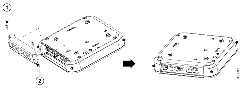
The antitamper bracket can be ordered to prevent the disconnection of cables. All the cables can be connected after the antitamper bracket is assembled, although it is simpler to connect the GPS before securing the bracket. After you have assembled the bracket, the cable connections can be removed with a tool, such as a flat-head screwdriver, except for the GPS, which requires a box-end wrench to be removed while the bracket is assembled.

Figure 7. Attaching the Antitamper Bracket

1

Secure screws

2

Antitamper bracket

Power Guidelines and Requirements

Check the power at your site to ensure that you are receiving power that is free of spikes and noise. Install a power conditioner, if necessary.

Powering the Cisco Catalyst Cellular Gateway Unit

The following sections explain how to power on a Cisco Catalyst Cellular Gateway unit:

  • AC source (with an AC/DC power converter)

  • PoE through a PoE injector (if PoE is not available, from a network source)

  • PoE from a network source

The Cellular Gateway is powered by either AC source or PoE through the Gigabit Ethernet WAN port:

  • An AC power socket is for use with an AC/DC power converter. The AC/DC power converter is always provided.

  • The unit can be powered with PoE through the Gigabit Ethernet WAN port when there is an internal PoE card.


Note


If the unit is provisioned for PoE powering, the unit can have both AC and PoE power sources connected, in which case, the unit will default to AC source with PoE as the backup source.


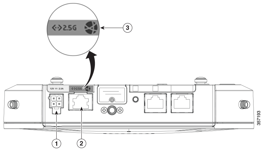
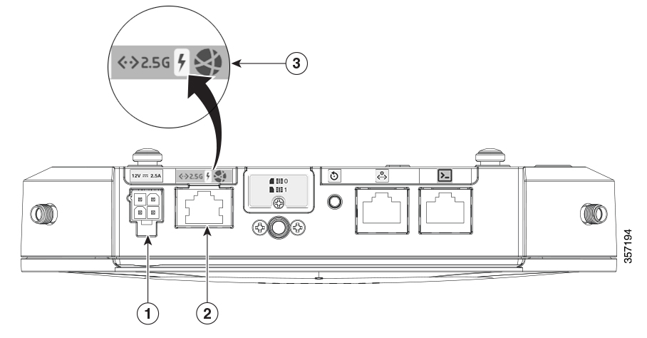
POE is a factory installed option only and must be selected at the time of ordering the Cellular Gateway. POE-enabled units are distinguished by the lightning bolt icon over the GE-WAN port.

Figure 8. PWR and Gigabit Ethernet WAN label: PoE not provisioned

1

Power socket (AC/DC converter)

2

Gigabit Ethernet WAN port

3

Gigabit Ethernet WAN labelling; If lightning bolt is not present, it indicates that PoE is not provisioned

Figure 9. PWR and Gigabit Ethernet WAN Label: PoE is Provisioned

1

Power socket (AC/DC converter)

2

Gigabit Ethernet WAN port

3

Gigabit Ethernet WAN labelling; If lightning bolt is present, it indicates that PoE is provisioned

AC/DC Power Converter Connecter

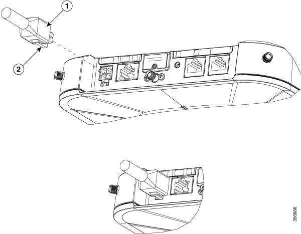
The AC/DC power converter connector has a lock-latch for being secured to the unit when installed. To remove the connector, depress the back of the latch and remove the connection.

Figure 10. AC/DC Power Converter Connector

1

AC/DC Power Converter connector

2

Lock latch

Installing the Power Injector

The typical power injector package contains the following items:

  • Power injector

  • Power cord

  • URL pointer card and China RoHS statement

Figure 11. Cisco Catalyst Cellular Gateway powered through PoE

Note


The Cisco Catalyst Cellular Gateway can be powered through PoE using a power injector module developed for Cisco APs, even when a PoE is not available from the network source. For more information, see the Cisco Aironet Power Injector Installation Guide.


Grounding the Connection

Grounding is not always required for indoor installations because the Cisco Catalyst Cellular Gateway units are classified as low-voltage devices and do not contain internal power supplies. We recommend that you check your local and national electrical codes to see if grounding is a requirement.

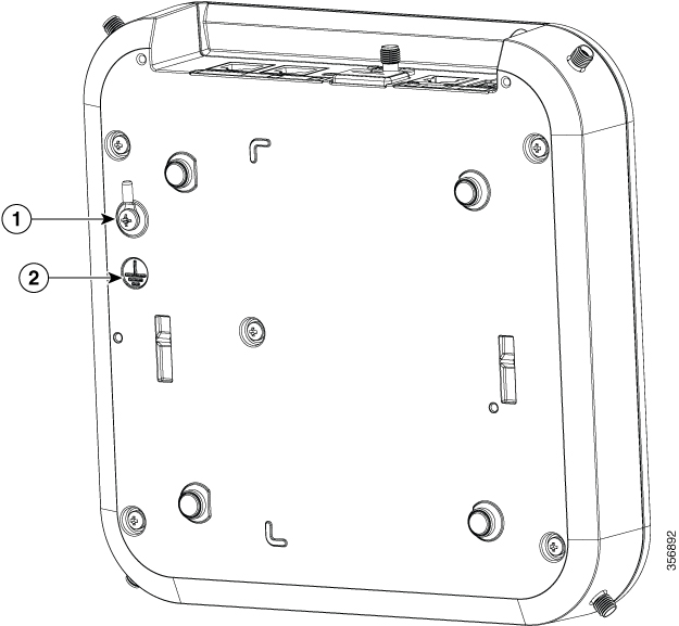
The chassis must be grounded to provide ESD protection when the unit is powered with PoE. If grounding is required in your area, or you want to ground your cellular gateway unit, follow these steps:

Step 1: Power off the Cisco Catalyst Cellular Gateway unit by setting the power switch (or switches) to the Off position.

Step 2: Strip the covering from the end of the grounding wire. The amount of covering to be stripped varies depending on the type of lug you plan to attach to the wire.

Step 3: Insert the stripped end of the grounding wire into the open end of a lug and crimp the grounding lug securely to the wire.

Step 4: Attach the grounding lug firmly to the threaded hole on the unit using a Philips screwhead screw.

1

Safety ground:

  • Ring terminal: 22-16 AWG

  • Uninsulated M3.5 Securing screw: Torque

2

Ground symbol


Note


The Cisco Catalyst Cellular Gateway is supplied with a ring lug and securing screws for grounding the Cisco Catalyst Cellular Gateway unit, when required. The unit must be grounded to provide ESD protection when the unit is powered with PoE. Ensure that you use an 18-AWG insulated wire.