Install and Connect Cisco ISR 1100 and ISR 1100X Series Routers

This chapter describes how to install and connect Cisco ISR 1100 and ISR 1100X Series Routers.

Unpack Router

Do not unpack the router until you are ready to install it. If the final installation site is not yet ready, keep the chassis in its shipping container to prevent accidental damage.

The router, accessory kit, publications, and any optional equipment that you ordered may be shipped in more than one container. When you unpack the containers, check the packing list to ensure that you received all the items on the list.

Install Cisco ISR 1100 and ISR 1100X Series Routers

Cisco ISR 1100 and ISR 1100X Series Routers can be installed in the following ways:


Warning


Statement 1004

Read the installation instructions before using, installing or connecting the system to the power source.


Warning


Statement 1074

Installation of the equipment must comply with local and national electrical codes.


Warning


Statement 1005—Circuit Breaker

This product relies on the building’s installation for short-circuit (overcurrent) protection. To reduce risk of electric shock or fire, ensure that the protective device is rated not greater than:

20A


Warning


This product is a Class 1 laser product.


Warning


Statement 1076

To prevent airflow restriction, allow clearance around the ventilation openings to be at least: 1.75 in. (4.4 cm).


Mount the Router on a Desk or Shelf

You can mount the chassis on a desktop by placing it on a desk in a horizontal position. Make sure there are no blockages or obstructions within one inch of the top of the chassis or within 0.5 inches of the sides so that nothing interferes with cooling.

The bottom of the router has four rubber feet that protect the router and the surface. Do not remove the rubber feet included with the chassis. They are needed for proper cooling.

Figure 1. Mount on a Desk or Shelf

Note


Do not stack routers.


Mount the Router on a Wall

Cisco ISR 1100 and ISR 1100X Series routers designed for wall-mounting have mounting holes on the bottom of the chassis for securing with screws or anchors to a vertical surface. Note the UP marking on the bottom of the chassis, indicating the correct direction for mounting the router.


Note


Read the wall-mounting instructions carefully before beginning installation. Failure to use the correct hardware or to follow the correct procedures could result in a hazardous situation to people and damage to the system. Statement 378


Note


For safety reasons, the only supported wall-mount orientation is as shown in step 3 below. The mounting slots support only this orientation. Marking is provided on the bottom of the router (see step 1) showing the correct orientation.


Note


When choosing a location for wall mounting the router, consider cable limitations and wall structure.


  1. Determine where to drill holes in the wall, based on the positions of the mounting holes on the router. The following figure shows the wall-mount holes located on the underside of the router.

  2. Drill holes in the wall in the correct positions for the router mounting holes.

  3. Insert screws, using anchors if necessary, depending on the wall material. Use screws that fit the mounting holes on the router. A minimum of .073 inch (1.9 mm) is required between the screw head and the wall in order to secure the router to the wall.

  4. Hang the router on the screws without forcibly pushing towards the wall side.

Mount the Router on a Rack Tray

You can mount Cisco ISR 1100 and ISR 1100X Series routers on an equipment rack tray (product ACS-1100-RM1-19) designed specifically for these devices. There are two options for securing the router to the rack tray:

  • Secure the router and external power supply using straps.

  • Secure the router using mounting screws and the external power supply using a strap.

You can mount the router with the front panel, containing the ports, facing the front of the rack tray or the back of the tray.

Secure the Router and Power Supply Using Straps

  1. Place the router and external power supply onto the rack tray as shown in the following figure. You can mount the router with the front panel, containing the ports, facing the front of the tray or facing the back of the tray.

  2. Using the straps included with the rack tray, secure the external power supply and the router chassis, as shown.

    Use only one strap to secure the chassis. Ensure that the strap does not cover any of the ventillation holes. Blocking ventillation holes affects airflow and can interfere with router cooling.

  3. Bundle any excess length of the power cable using plastic cable ties and secure the cable to the tray using one of the bridge lance attachment points on the left side of the tray, near the power supply position.

Secure the Router Using Mounting Screws

  1. On the bottom of the router, remove the four screws that secure the router cover.

  2. Secure the router to the rack tray using the M3 mounting screws from the rack tray kit. Tighten to between 5 and 6.8 inch pounds of torque. You can mount the router with the front panel, containing the ports, facing the front of the tray or facing the back of the tray.


    Note


    If there is equipment installed above and below the rack position intended for the tray and router, it may be easier to mount the router to the tray before installing the tray in the rack. This ensures clear access for positioning the router on the tray and for inserting the mounting screws.


  3. Place the external power supply onto the rack tray and use a strap included with the rack tray to secure the power supply.

  4. Bundle any excess length of the power cable using plastic cable ties. Secure the cable to the tray using one of the bridge lance attachment points on the left side of the tray, near the power supply position.

Connect Cisco ISR 1100 and ISR 1100X Series Routers

Chassis Grounding


Warning


Connect the Chassis to Earth Ground—To reduce the risk of electric shock, the chassis of this equipment needs to be connected to permanent earth ground during normal use. Statement 445


Warning


Only trained and qualified personnel should be allowed to install, replace, or service this equipment. Statement 1030


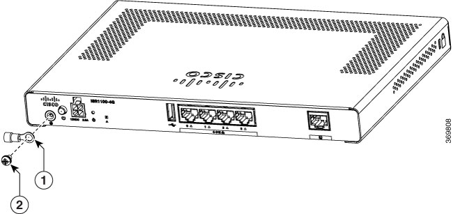
To meet safety and electromagnetic interference (EMI) requirements and to ensure proper operation of Cisco ISR1100 and ISR1100X Series routers, connect the router to a reliable earth ground before powering it on.


Note


You need to use your own 14 AWG copper wire and ring terminal. These are not part of the accessory kit.


  1. For grounding the chassis, use a copper wire of size 14 AWG and a ring terminal.

  2. Strip one end of the ground wire to the length required for the ground lug or the ring terminal, and attach the ring terminal to the cable.

  3. Crimp the ground wire to the ground lug or ring terminal, using a crimp tool of the appropriate size.

  4. Make sure that the cable does not touch or block access to other router components.

  5. Using a number 2 Phillips (+) screwdriver, attach the ground lug to the router using the UNC 6-32 screw included with the router. Tighten to between 8.3 and 11.0 inch pounds of torque.

Figure 2. Chassis Grounding for Cisco ISR1100 and ISR1100X Series Models (Cisco ISR1100-4G Model Shown)

1

Ground Lug

2

Screw (UNC 6-32)

Connect the Power Cable

Before you connect power to the router, ensure that you have:

  • Electrostatic discharge (ESD) grounding strap.

  • Power cords appropriate for your location.

Connect Router to AC Power

Before you power the router, first ensure that it is connected to earth ground. Next, plug the power supply output cable to the 4-pin power connector on the front panel. Finally, plug the input power cord to the AC power source.

When removing the power connector, press the latch on the top of the connector to release it from the socket.


Warning


To prevent the system from overheating, do not operate it in an area that exceeds the maximum recommended ambient temperature of 104°F (40°C). Statement 1047


Figure 3. Power Connector

Item

1

Power Cable Connector

Connect the Router to a Console

You can configure and manage Cisco ISR1100 and ISR1100X Series routers using a management console. To connect the router to a management console, use the console port which accepts a cable with an RJ-45 connector.

To connect the router to a console:

  1. Connect the end of the console cable with the RJ-45 connector to the console port on the router.

  2. Connect the end of the cable with the DB-9 connector (or USB Type-A) to the terminal or PC. If your terminal or PC has a console port that does not accommodate a DB-9 connector, you must provide an appropriate adapter for that port.


Caution


Power over Ethernet (PoE) enabled cables can damage the console port. Do not accidentally connect these cables to the console port.