Get Started with Cisco SD-WAN Cloud onRamp for Colocation Solution

Cisco SD-WAN Cloud onRamp for Colocation Solution–Deployment Workflow

This topic outlines the sequence of how to get started with the colo devices and build clusters on Cisco vManage. Once a cluster is created and configured, you can follow the steps that are required to activate the cluster. Understand how to design service groups or service chains and attach them to an activated cluster. The supported Day-N operations are also listed in this topic.

  1. Complete the solution prerequisites and requirements. See Prerequisites and Requirements of Cisco SD-WAN Cloud onRamp for Colocation Solution.

    • Complete wiring the CSP devices (set up CIMC for initial CSP access) and Cisco Catalyst 9500-40X or Cisco Catalyst 9500-48Y4C switches (set up console server) along with OOB or management switches. Power on all devices.

    • Set up and configure DHCP server. See Provision DHCP Server Per Colocation .

  2. Verify the installed version of Cisco NFVIS and install NFVIS, if necessary. See Install Cisco NFVIS Cloud OnRamp for Colocation on Cisco CSP .

  3. Set up or provision a cluster. A cluster constitutes of all the physical devices including CSP devices, and Cisco Catalyst 9500-40X or Cisco Catalyst 9500-48Y4C switches. See Get Started with Cisco SD-WAN Cloud onRamp for Colocation Solution.

  4. Activate a cluster. See Create and Activate Clusters.

  5. Design service group or service chain. See Manage Service Groups.


    Note

    You can design a service chain and create a service group anytime before creating clusters or activating clusters after all VMs are uploaded to the repository.
  6. Attach or Detach service group and service chains to a cluster. See Attach or Detach a Service Group in a Cluster.


    Note

    Service chains can be attached to a cluster after the cluster is active.
  7. (Optional) Perform all Day-N operations.

Install Cisco NFVIS Cloud OnRamp for Colocation on Cisco CSP

This section provides information about a series of tasks you need to perform to install NFVIS Cloud OnRamp for Colocation on a Cisco CSP device.

Log Into CIMC User Interface

Before you begin

  • Ensure that you have configured the IP address to access CIMC.

  • If not installed, install Adobe Flash Player 10 or later on your local system.

For details on how to configure an IP address for CIMC, see the Set up CIMC for UCS C-Series Server guide on cisco.com.

For information about upgrading CIMC, see the CIMC Firmware Update Utility guide on cisco.com.

Procedure


Step 1

In your web browser, enter the IP address that you configured to access CIMC during initial setup.

Step 2

If a security dialog box displays, do the following:

  1. Optional: Select the check box to accept all content from Cisco.

  2. Click Yes to accept the certificate and continue.

Step 3

In the log in window, enter your username and password.

When logging in for the first time to an unconfigured system, use admin as the username and password as the password.

Step 4

Click Log In.

The Change Password dialog box only appears the first time you log into CIMC.

Step 5

Change the password as appropriate and save.

The CIMC home page is displayed.

Step 6

From the CIMC Server tab, select Summary, and click Launch KVM Console.

The KVM Console opens in a separate window.

Step 7

From the Virtual Media menu on the KVM Console, select Activate Virtual Devices.

If prompted with an unencrypted virtual media session message, select Accept this session, and click Apply. The virtual devices are activated now.

Step 8

From the Virtual Media menu on the KVM Console, select Map CD/DVD.

Step 9

Browse for the installation file (ISO) on your local system, and select it.

Step 10

Click Map Device.

The ISO image file is now mapped to the CD/DVD.

Step 11

From the CIMC Server tab, select BIOS.

For more information about upgrading BIOS, see the BIOS Upgrade guide on cisco.com.

Step 12

From the BIOS Actions area, select Configure Boot Order.

The Configure Boot Order dialog box appears.

Step 13

From the Device Types area, select CD/DVD Linux Virtual CD/DVD, and then click Add.

Step 14

Select HDD, and then click Add.

Step 15

Set the boot order sequence using the Up and Down options. The CD/DVD Linux Virtual CD/DVD boot order option must be the first choice.

Step 16

To complete the boot order setup, Click Apply.

Step 17

Reboot the server by selecting the Power Off Server option from the Server Summary page in CIMC.

Step 18

After the server is down, select the Power On Server option in CIMC.

When the server reboots, the KVM console will automatically install Cisco Enterprise NFVIS from the virtual CD/DVD drive. The entire installation might take 30 minutes to one hour to complete.

Step 19

After the installation is complete, the system is automatically rebooted from the hard drive. Log into the system when the command prompt changes from "localhost" to "nfvis" after the reboot.

Wait for some time for the system to automatically change the command prompt. If it does not change automatically, press Enter to manually change the command prompt from "localhost" to "nfvis". Use admin as the login name and Admin123# as the default password.

Note 
The system prompts you to change the default password at the first login. You must set a strong password as per the on-screen instructions to proceed with the application. You cannot run API commands or proceed with any tasks unless you change the default password at the first login. API will return 401 unauthorized error if the default password is not reset.
Step 20

You can verify the installation using the System API or by viewing the system information from the Cisco Enterprise NFVIS portal.


Note

Ensure that the RAID configuration is 4.8 TB RAID-10. To configure RAID through CIMC, see the Cisco UCS Servers RAID Guide on cisco.com.

Activate Virtual Device

You will have to launch the KVM Console to activate virtual devices.

Before you begin

Ensure that you have the Java 1.6.0_14 or a higher version installed on your local system.

Procedure


Step 1

Download the Cisco Enterprise NFVIS image from a prescribed location to your local system.

Step 2

From CIMC, select the Server tab, and click Launch KVM Console.

Note 

A JNLP file will be downloaded to your system. You must open the file immediately after it is downloaded to avoid the session timeout.

Step 3

Open the renamed .jnlp file. When it prompts you to download Cisco Virtual KVM Console, click Yes. Ignore all security warnings and continue with the launch.

The KVM Console is displayed.

Step 4

From the Virtual Media menu on the KVM Console, select Activate Virtual Devices.

If prompted with an unencrypted virtual media session message, select Accept this session, and click Apply. The virtual devices are activated now.


Map NFVIS Cloud OnRamp for Colocation Image

Procedure


Step 1

From the Virtual Media menu on the KVM Console, select Map CD/DVD....

Step 2

Browse for the installation file (ISO) on your local system, and select it .

Step 3

Click Map Device.

The ISO image file is now mapped to the CD/DVD.
Step 4

From the KVM console, power cycle (warm reboot) and system installation process starts and NFVIS is installed.


Bring up Cisco Cloud Services Platform Devices

Table 1. Feature History

Feature Name

Release Information

Description

Onboarding CSP Device with Day-0 Configuration Using USB Drive

Cisco SD-WAN Release 20.4.1

This feature enables you to onboard CSP devices by loading the Day-0 configuration file to a USB drive. Use this onboarding option when you can't access the Internet to reach the Plug-and-Play Connect server.

To bring up the Cisco Cloud Services Platform (CSP) devices, you can use the following options:

  • Automated deployment: Securely onboards and deploys CSP devices with factory settings into the Cisco SD-WAN network during the Day-0 configuration. The deployment dynamically discovers the IP address of Cisco vBond Orchestrator using the Plug-and-Play (PnP) process for Cisco CSP devices.

  • Bootstrap deployment: Requires you to share the configuration files with the CSP devices. You can either create a configuration file and copy it to a bootable USB, or add the configuration file to the USB. The bootable USB is connected and available on the devices at the time of bootup.

Onboard CSP Devices Using Plug-and-Play Process

This topic describes how the bringing up of Cisco CSP devices are automated using the PnP process.

Before you begin

  • Ensure that you connect the CSP devices as per the prescribed topology, and power them on.

  • Connect the Plug-and-Play (PnP) supported interface to the WAN transport (typically Internet).

Power on a Cisco CSP device. The following process occurs:

Procedure


Step 1

When the device boots up, it obtains the IP address, default gateway, and DNS information through the DHCP process on the supported PnP interface of the device.

Step 2

The device connects with the Cisco cloud hosted PnP Connect server and shares its chassis or serial number with the PnP server to be authenticated by it.

Step 3

After authentication, the PnP Connect portal provides the device with information about the Cisco vBond Orchestrator, organization name, and root certificates.

For deployments that use enterprise root-ca certificate, information about Cisco vBond Orchestrator IP address or DNS, organization-name, and enterprise root-ca certificate are downloaded on the device from the PnP Connect portal using the HTTPS protocol. The device uses this information to initiate control connections with the Cisco vBond Orchestrator.

You can view the availability of the device and association with the Cisco vBond Orchestrator on the PnP interface through the PnP Connect portal.

Step 4

The PnP Connect portal then displays a Redirect Successful status when the device is redirected through PnP to the Cisco vBond Orchestrator.

Step 5

After authentication with the Cisco vBond Orchestrator, the device is provided with Cisco vManage and Cisco vSmart Controller information to register and establish a secure connection.

Step 6

The device attempts to establish a secure control connection with the Cisco vManage server.

Step 7

After authentication with the Cisco vBond Orchestrator, the Cisco vManage server responds to the device with the system IP of the device and reauthenticates the device using the shared system-ip information.

Step 8

To join the Cisco SD-WAN overlay network, the device reinitiates control connections to all the SD-WAN controllers using the configured system-ip IP address.


Onboard CSP Devices Using USB Bootstrapping Process

If you're unable to use the automated discovery option, use this deployment option to configure the factory-shipped device, which comes without any configuration.

We recommend this deployment option when:

  • The device is connected to a private WAN transport (MPLS) that can’t provide a dynamic IP address.

  • Internet access isn't available to reach the Plug-and-Play Connect server.

Points to Consider

  • The USB drive can have multiple Day-0 configuration files, which are identified by the serial number of the device in the file name. This naming convention enables you to use the same USB drive for bootstrapping multiple devices.

  • The supported Day-0 configurations included in the configuration file are:

    • Static IP configuration of the device

    • Cisco vBond Orchestrator IP address and the port configuration

    • DNS server and domain name configuration

  • The bootstrap configuration can be uploaded to a USB key and inserted into a device at the install site.

Before you begin

  • The device must be in factory default state with no added configuration.

  • The device must be installed with a fresh image of Cisco NFVIS.

  • The USB drive must be Virtual File Allocation Table (VFAT) formatted to recognize and automount the drive. Insert the USB drive into a laptop or desktop to format it.

  • The device should be able to reach the Cisco vBond Orchestrator.

Procedure


Step 1

Create a configuration file on the root folder of the USB drive.

Ensure that the configuration file name is, nfvis_config_SERIAL.xml, where

SERIAL represents the serial number of the CSP device.

For example,

nfvis_config_ WZP232903K6.xml

Step 2

Copy the following to the configuration file.

<config xmlns="http://tail-f.com/ns/config/1.0">
       <vm_lifecycle xmlns="http://www.cisco.com/nfvis/vm_lifecycle">
  <networks>
  <network>
    <name>int-mgmt-net</name>
    <subnet>
      <name>int-mgmt-net-subnet</name>
      <address>192.168.30.6</address>
      <netmask>255.255.255.0</netmask>
      <gateway>192.168.30.1</gateway>
    </subnet>
  </network>
  </networks>
       </vm_lifecycle>

<system xmlns="http://viptela.com/system">
        <organization-name>vIPtela Inc Regression</organization-name>
        <sp-organization-name>vIPtela Inc Regression</sp-organization-name>
       <vbond>
          <remote>172.23.191.87</remote>
          <port>12346</port>
        </vbond>
      </system>

<vpn xmlns="http://viptela.com/vpn">.
        <vpn-instance>
          <vpn-id>0</vpn-id>
          <interface>
            <if-name>colo-mgmt</if-name>
            <tunnel-interface>
              <encapsulation>
                <encap>ipsec</encap>
              </encapsulation>
            </tunnel-interface>
            <shutdown>false</shutdown>
          </interface>
          </vpn-instance>
          </vpn>         
          </config>
Note 
It’s mandatory to copy the above-mentioned static IP configuration of the device to the configuration file. The static IP configuration of the device is represented by the following Day-0 configurations:
<address></address>, <netmask></netmask>, and <gateway></gateway>
Step 3

Insert the USB drive into the Cisco CSP device and power on the device.

When the device boots up, the device searches for the configuration file in the bootable USB drive. After the file is located, the device suspends the PnP process and loads the bootstrap configuration file.
Step 4

Remove the USB drive.

Note 

If you don’t unmount the USB drive and reboot the device after the configuration has been applied, the USB drive configuration isn’t reapplied. The CSP device isn’t in Factory Data Reset (FDR) state or restored to its original system state.

Step 5

To access a CSP device, SSH to a static IP address provided in Step 2 such as, 192.168.30.6.

Step 6

Change the default password at the first login when the system prompts you to change.

Ensure that you set a strong password based on the on-screen instructions. You can't run API commands or proceed with any tasks unless you change the default password at the first login.


What to do next

To verify the device onboarding process, proceed to Verify Onboarded Devices and Activate Devices.

Verify Onboarded Devices and Activate Devices

Procedure


Step 1

Log in to Cisco vManage with admin credentials using the URL HTTPS: //vManage-ip-address/.

Step 2

Click Configuration > Devices.

From the list of devices, the CSP devices that have the serial number with the word token aren’t yet onboarded. To authenticate these devices with the SD-WAN controllers, Cisco vManage provides a One-Time Password (OTP). The OTP is autogenerated by Cisco vManage after adding the CSP device in the SD-WAN controller authorized device list.

Step 3

Under the Valid column, verify the validity of the installed certificate of all the listed CSP devices. See Failures with Certificate installation. Also, verify if root CA has been installed. See CSP hasn’t established connectivity with Cisco vManage.

Note 
For device onboarding using enterprise root-ca certificates, the CSP device receives the root certificates, along with the Cisco vBond Orchestrator and organization name information from the PnP Connect portal.
Step 4

To activate the CSP device and associate the chassis number and the Serial No (one-time password) with the CSP device, on the CLI of the CSP device, use the following command:

request activate chassis-number chassis-number token token-number

For more information about the request device command, see request device.

Example:

request activate chassis-number CSP-5444-serial-number token 70d43cfbd0b3b426da63dba2dd4f4c49
Step 5

To bring up the remaining CSP devices, repeat Steps 1–4 for each of the CSP devices.


Bring up Switch Devices

This section describes about how Cisco Catalyst 9500-40X or Cisco Catalyst 9500-48Y4C switch devices are brought up through the Day-0 configuration.

Before you begin

Ensure that you note the following before bringing up the switch devices:
  • Cisco Catalyst 9500-40X or Cisco Catalyst 9500-48Y4C switch devices have both Network-Advantage and DNA-Advantage licenses. To verify the available licenses on the switch devices, use the following command:
    Device# show license status
    To know more about the license usage information, see the show license usage command.
  • Either PNP redirect setup or manual PNP profile being set on the switch devices is required. For a PNP redirect setup, add switches SN and Cisco Colo Manager IP address to PNP, and add entries of devicehelper.cisco.com to OOB router of the network if the DHCP server is on OOB router. For example,
    #conf t
    #ip host devicehelper.cisco.com <OOB router of the network>
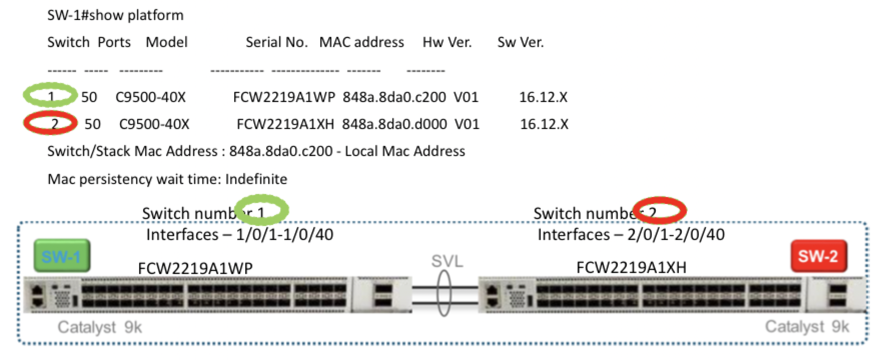
  • Ensure that both switches are connected as per the SVL mode configuration.

Procedure


Step 1

Clean the switch configuration if they have been previously used.

  1. Renumber switch, which is required for SVL stack mode.

    Note 

    Ensure that you do not touch the switches during SVL mode. Also, do not perform any action such as, pressing enter or space, which can cause switches to complete SVL.

    Use the show switch command to determine the switch number and whether the provisioned switch exists in the switch stack. If the switch number is two, then use the switch 2 renumber 1 command, and then erase the configuration.

  2. To erase the switch startup configuration and return it to its initial state, use the write erase command.

  3. To reload the switch with a new configuration, use the following commands in privileged EXEC mode and enter no for not saving the modified configuration:

    switch(config)#reload

    Note 

    You do not need to save the configuration.

  4. Perform steps b and c on the secondary switch device after the switch stack reloading has been completed. This action ensures that the secondary switch device is reloaded twice.

Step 2

After Cisco Catalyst 9500-40X or Cisco Catalyst 9500-48Y4C switch boots up, it gets an IP address from the local DHCP server and initiates PNP discovery.

Step 3

The DHCP server with option 43 enables Cisco Catalyst 9500-40X or Cisco Catalyst 9500-48Y4C switch to reach the PNP server in Cisco Colo Manager.

The Cisco Colo Manager IP address is the PNP server IP address of a cluster on Cisco vManage. Ensure that DHCP server with option 43 always point to the port, 9191.

Example:

The following is an example of local PNP server for switches:
ip dhcp pool Cat9k
network 10.114.11.39 255.255.255.0
dns-server 172.31.232.182 
default-router 172.31.232.182
option 43 ascii "5A;B2;K4;I10.114.11.40;J9191”

Where, 10.114.11.40 is the local PNP server or Cisco Colo Manager IP address.

The output after setting DHCP server with option 43 to port, 9191 is:

ip dhcp excluded-address 172.31.232.182 172.31.232.185
ip dhcp excluded-address 172.31.233.182
ip dhcp excluded-address 172.31.232.254
ip dhcp excluded-address 172.31.23.10 172.31.23.49
ip dhcp excluded-address 172.31.23.52 172.31.23.100
ip dhcp excluded-address 172.31.23.252
ip dhcp excluded-address 172.31.23.253
ip dhcp excluded-address 172.31.23.230 172.31.23.250
!
Step 4

After the switches reach the PNP server on Cisco Colo Manager, it pushes the Day-0 configuration. The Day-0 configuration push happens if a cluster is activated on Cisco vManage. If a cluster is not activated, the Cisco Catalyst 9500-40X or Cisco Catalyst 9500-48Y4C switches reach the PNP server on Cisco Colo Manager every minute and stays in backoff mode.


After the switch devices are brought up, the SSH connection and NETCONF sessions on the switch devices are enabled for Cisco Colo Manager to push Day-N configuration and ongoing switch management is continued.

Example

About Uplink Ports 36 and 37 in Prescriptive Connections

For prescriptive connections, ports 36 (input VLAN handoff) and 37 (output VLAN handoff) are reserved for uplink ports.


Note

The 1/0/36, 1/0/37 and 2/0/36, 2/0/37 switch ports are configured in "active" mode. If a user is not using port channel and not connected to ports 36 and 37, the OOB switch ports that are connected to Cisco Catalyst 9500-40X on ports 36 or 37 must be configured as "passive" mode.

For example,

  • interface Port-channel1 switchport trunk allowed VLAN 100-106

    example VLANs
     switchport mode trunk
    !
  • interface TenGigabitEthernet1/0/1

    port connected to cat9k 1/0/36 or 1/0/37
     switchport mode trunk
     channel-group 1 mode passive
     spanning-tree portfast
    !
  • interface TenGigabitEthernet1/0/2

    interface TenGigabitEthernet1/0/2
     switchport mode trunk
     channel-group 1 mode passive
     spanning-tree portfast
    !

What to do next

To bring up another switch, repeat all the mentioned steps in sequence for the next switch.

Bring up Cisco Colo Manager

This section describes about how Cisco Colo Manager is brought up. The Cisco Colo Manager acts as a PNP agent for the Catalyst 9K switches in a cluster. It takes care of the Day-0 configuration push to the Catalyst 9K switches and also relays the configuration from Cisco vManage to Catalyst 9K.


Note

During cluster activation process, Cisco Colo Manager is automatically brought up.


Procedure


Step 1

All CSP devices in the cloud onramp for colocation establish a DTLS tunnel with Cisco vManage.

Step 2

Cisco vManage selects one CSP device by sending a NETCONF action API to bring up Cisco Colo Manager on that CSP device.

Step 3

Cisco Colo Manager is in "Starting" state when it is brought up. Cisco Colo Manager can then move to "Healthy" or "Unhealthy" state depending on the health check status.


What to do next

After switch configuration and once colo manager is up, both switches reach the colo manager. Ensure that you check the PNP list on Cisco Colo Manager to verify that both the switch devices have called home. See Switch devices are not calling home to PNP or Cisco Colo Manager.

Note

For activation to continue, both switches must call home.

Provision and Configure Cisco SD-WAN Cloud onRamp for Colocation Solution

To order Cisco SD-WAN Cloud onRamp for Colocation PID, choose Cisco SD-WAN Cloud onRamp for Colocation on Cisco Commerce Workspace (CCW).

Customer-specific order details such as, Smart Account name, Virtual Account name must be provided while ordering.

To provision and configure the Cisco SD-WAN Cloud onRamp for Colocation solution, perform the following:

  1. Ensure that Cloud Service Platform (CSP) devices and Cisco Catalyst 9500-40X or Cisco Catalyst 9500-48Y4C switches are cabled as per the prescribed or flexible connections, and powered on.

  2. The Smart Account synchronizes customer-specific device order details with PNP Connect and vOrchestrator.

Provision DHCP Server Per Colocation

To manage IP addresses of the physical devices such as switches, VNFs, and CSP devices, you must configure a DHCP server per colocation. The Cisco Colo Manager IP address can be configured in DHCP option 43 for Cisco Catalyst 9500-40X or Cisco Catalyst 9500-48Y4C to reach Cisco Colo Manager.

Cisco vManage fixes and assigns Cisco Colo Manager IP addresses for a colocation. It manages and assigns IP addresses of all VNFs through Day-0 configuration.


Note

The subnet for both physical (CSP devices, switches) and virtual appliances (Cisco Colo Manager, VNF) must be same.


You can pick an appropriate subnet for a colocation and limit the pool for IP addresses depending on the number of CSP devices and switches in a colocation. Cisco vManage picks the first IP address entered in the VNF management IP pool in the Cisco vManage interface and configures it as the (Switch PNP Server IP) Cisco Colo Manager IP address. The second and third IP addresses form the management pool are used for switch management IP addresses. The Switch PNP Server IP field can be edited to provide an alternative IP address if a different IP address is configured in the DHCP server for PNP of switches. The remaining IP addresses from the Cisco vManage pool are assigned to the remaining VNFs in the colocation.


Note

Ensure that you set up a DNS server in each colocation.


Device Port Connectivity Details and Service Chaining for Prescriptive Connections

In Cisco SD-WAN Cloud onRamp for Colocation solution deployments, the Cisco Catalyst 9500-40X switches connected to CSP systems perform service chaining. If VMs support SR-IOV, Cisco Catalyst 9500-40X switches perform service chaining, whereas VMs without SR-IOV support, service chaining is done by Open Virtual Switch (OVS).

Virtual switch-based service chains are used for High Availability traffic and control traffic.

VLAN-based L2 service chaining from Cisco Catalyst 9500-40X switch is used for Cisco SD-WAN Cloud onRamp for Colocation solution. In this service chaining, each virtual NIC interface of a VM in a service chain is configured on the same access VLAN on a CSP virtual switch. The switch pushes the VLAN tag of the packets entering and leaving the vNIC interface. The VNF can remain unaware of the next service in the service chain. To forward traffic between the VNFs hosted either on the same CSP or across different CSP devices in a cluster, the physical switch with the matching VLAN gets configured.

In Cisco SD-WAN Cloud onRamp for Colocation solution deployments, the deja-vu check is disabled on the switch ports that are connected to the CSP devices for unicast traffic.

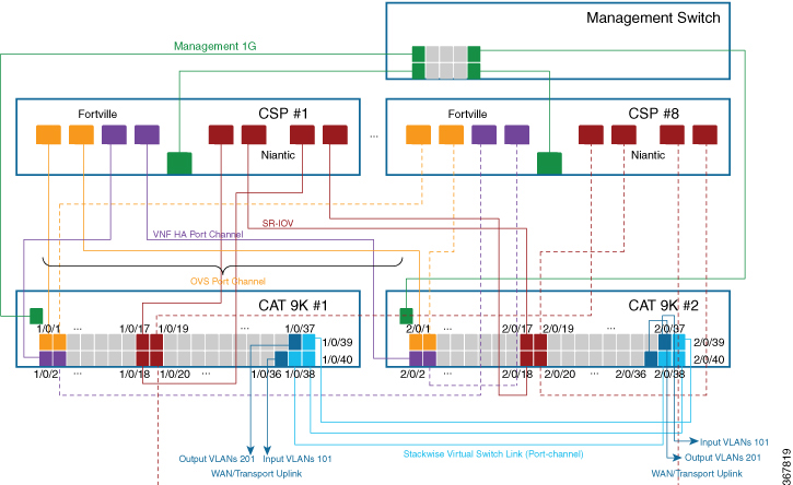
The following topology displays connectivity of the CSP ports to Cisco Catalyst 9500-40X switches and the OOB switch.

Figure 1. Service Chain Connectivity with OVS, VEPA Enabled Switch Ports
The image displays the connectivity of the CSP ports to Catalyst 9500 switches and OOB switch that performs service chaining.

The following is the location of an interface in switches:


Note

The location of an interface is applicable once switches are in SVL mode after successful cluster activation.


The following ports are VEPA disabled and configured with port channels:

  • 1/0/1-1/0/16

  • 2/0/1-2/0/16

The following ports are VEPA enabled and port channels configuration is disabled:

  • 1/0/17-1/0/32

  • 2/0/17-2/0/32


Note

VEPA ports are only applicable to SRIOV interfaces.


The following ports are the WAN connectivity ports:

  • 1/0/36, 2/0/36—Connect port 1/0/36 to receive outside traffic from branch/VPN connections (via an OOB switch).

  • 1/0/37, 2/0/37—Connect port 1/0/37 to forward service chain traffic to specific VLANs that is mapped to provider networks on an OOB switch.

You can connect the ports as follows:

  • Data ports—Connect ports 1/0/1-1/0/35 to CSP devices. To achieve redundancy and HA across switches, you can connect two ports to one CSP and the other two can be connected to next CSP. For example, ports 1/0/1 and 2/0/1 is used for data and HA respectively can be connected to the first CSP, CSP #1. Next, 1/0/2 and 2/0/2 is another port channel that is connected to the next CSP, CSP #2, and so on. Hence, the OVS ports consume all eight CSP devices.

  • WAN connectivity ports—Connect port 1/0/36 on configured VLAN/s to receive outside traffic (Input VLAN handoff). Connect port 1/0/37 to forward service chain traffic to specific VLANs that is mapped to provider networks (Output VLAN handoff). External input or output VLAN traffic can come from branch or VPN connections and provider networks terminate at the Cloud OnRamp for Colocation through the OOB switch. For each service chain configured in the cluster and input or output VLAN configured for each service chain, the configuration on the ports, 36 and 37 occurs during service chain deployment.

    If ports 36 or 37 are connected to the OOB switch and not using port channels, ensure that all VLAN handoffs are configured either on input or output VLAN handoffs correspondingly. For example, if port 36 is connected, configure all VLAN handoff on input VLAN handoff for a service chain. If port 37 is s connected, configure all VLAN handoff on output VLAN handoff for a service chain.

  • Connect ports 1/0/38-1/0/40 in Stackwise Virtual Switch Link (SVL) configuration.

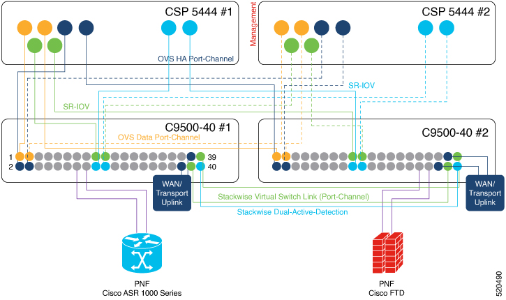
    The following cabling image shows how the physical network functions are connected to the Cisco Catalyst 9500-40X switches.

    Figure 2. PNF Cabling Image

    The following table provides the ports available for PNF:

    Table 2. Ports on Cisco Catalyst 9500-40X Switches for PNF

    Number of CSP Devices

    Number of PNFs

    Switch Ports available for PNFs on First Switch

    Switch Ports available for PNFs on Second Switch

    7

    1

    1/0/15-1/0/16,

    1/0/31-1/0/32

    2/0/15-2/0/16,

    2/0/31-2/0/32

    6

    2

    1/0/13-1/0/16,

    1/0/29-1/0/32

    2/0/13-2/0/16,

    2/0/29-2/0/32

    4

    4

    1/0/11-1/0/16,

    1/0/27-1/0/32

    2/0/11-2/0/16,

    2/0/27-2/0/32

To remove CSP devices and shuffle ports, perform the following steps:

  1. If all eight CSP devices are connected to switches and if you want to connect a PNF device to the switches:

    1. Deactivate or remove the eighth CSP (CSP connected to the right most data ports on switch) from the cluster by using the RMA workflow on Cisco vManage.

    2. Disconnect the CSP physical connections on Cisco Catalyst 9500-40X switches.

    3. Connect the PNF device in place of the disconnected CSP.

  2. If one of the first seven CSP devices must be removed to make additional ports available for PNF, perform the following steps:

    1. Perform the steps mentioned in 1.

    2. Move the right most connected CSP that is the eighth CSP to the ports that are made available by the removed CSP.

      For example, if the first CSP is removed, move the eighth CSP to the position of the first CSP and connect the PNF in place of the eighth CSP.

For the intial phase of Cisco SD-WAN Cloud onRamp for Colocation solution deployment, full chain VNF configuration is supported. In a full chain configuration, all the VNFs for the producer and consumer chains are part of a single service chain. The VNFs are not shared across different types of producers and consumers. A separate instance of a service chain supports each combination of consumer and producer type. For a full chain configuration, all the VNFs in a chain are L2 service chained.

Cisco vManage manages the Cisco SD-WAN Cloud onRamp for Colocation solution service chain configuration. Cisco vManage assigns the VLANs from the VLAN pool that is provided for the colocation to the individual VM VNICs and configures the switch with appropriate VLANs. The VNFs can remain unaware about the service chain. Apart from the Day-0 VNF configuration, Cisco vManage does not configure the individual VNFs that are part of the service chain. .

Validated Service Chains

In Cisco SD-WAN Cloud onRamp for Colocation solution deployments, the following are the four validated service chains that you can deploy within a cluster from Cisco vManage. For all the validated service chains, each VM can be instantiated in HA or standalone modes.

  • Employee Remote VPN Access—In this service chain, there is a firewall, which can be in L3 VPN HA or L3 VPN non-HA modes. The firewall VNFs can be ASAv, Palo Alto Networks Firewall, Firepower_Threat_Defense_Virtual (FTDv). Here, ASAv is in routed mode, no Day-0 configuration support for the VPN connect, no BGP on consumer chain, and no VLANs.

    Figure 3. Employee Remote VPN Access Service Chain
    The Employee Remote VPN Access Service Chain consists of a firewall that can be in L3 VPN HA or L3 VPN non-HA modes.
  • Internet Edge (Outbound Internet, eCommerce, SaaS)—In this service chain, a firewall is followed with a router. The firewall modes can be L3-VLAN HA and L3-VLAN non-HA. The routers can be in L3 HA and L3 non-HA modes. Here, ASAv is always in routed mode. One VLAN handoff is required and inbound subinterfaces can be up to four. The termination can be in routed mode or in a trunk mode with subinterfaces up to four. You can choose the hypervisor tagged VLANs versus VNF to do the VLAN tagging. In VNF VLAN tagging, you can terminate to a minimum of 1 VLAN and maximum of 4 VLANs. In hypervisor tagged VLANs, all VLANs are tagged in the same inbound VNF interface.

    Figure 4. Internet Edge Service Chain
    The Internet Edge (Outbound Internet, eCommerce, SaaS) Service Chain consists of a firewall followed with a router.
  • SD-WAN Access—In this service chain, vEdge is followed by a firewall, which is followed by a router. The firewall modes can be L2 HA, L2 non-HA, L3 HA and L3 non-HA. The routers can be in L3 HA and L3 non-HA modes.

    Figure 5. SD-WAN Access Service Chain
    The SD-WAN Access service chain consists of vEdge which is followed by a firewall, and then followed by a router.
  • Cloud Edge (Public Cloud Access)—In this service chain, firewall is followed by a router, where the firewall is in routed mode. The firewall modes can be, L3 HA and L3 non-HA. The routers can be in L3 HA and L3 non-HA modes. This service chain is Internet Edge (Outbound Internet, eCommerce, SaaS) with firewall mode being L3.

    Figure 6. Cloud Edge (Public Cloud Access) Service Chain
    The Cloud Edge (Public Cloud Access) service chain consists of a firewall, which is followed by a router, and the firewall is in routed mode.

See Create Service Chain in a Service Group topic about how you can choose the validated service chains through Cisco vManage.

Validated VM Packages

VM packages are created as per use cases. These packages have recommended Day-0 configuration for each supported use case. Any user can bring the required custom Day-0 configuration and package the VM as per their requirement. In the validated packages, various Day-0 configurations are bundled into a single VM package. For example, if a VM is a firewall VM, it can be used in transparent or routed mode if it is in the middle of a service chain. If a VM is the first or last VM in a service chain, it can be a terminating tunnel to a branch or provider, or routed traffic, or can terminate multiple branches, or a provider. Each use case is set up as a special tag in image metadata for a user to make a selection at deployment or while provisioning a service chain. If a VM is in the center of a service chain, Cisco vManage can automate the IP addresses and VLANs for those segments. If VM is terminating to a branch or provider, user must configure the IP addresses, peer addresses, autonomous system numbers, and others.

Customized Service Chains

Service chains are a named list of service-functions and associated endpoint-group through which packets flow. You can customize service chains and create service chain templates. A service chain template is a chain of VMs serving the intent of connecting the ingress traffic to the cloud. Service chain templates can have predefined service chains containing validated VMs .

The first VNF and the last VNF in a customized service chain can be a router (or firewall). In SD-WAN case, the first VM is a vEdge, which is orchestrated. In non-SD-WAN case, the first VM can be modeled as a gateway router, which is not orchestrated.

You can choose a service chain template and modify the template by inserting one or more VMs and delete one or more VMs. For each VM in the service chain, you can select the VM image that has been brought up from the VM catalog. For example, if the first VM in the service chain is a ROUTER, you can select either Cisco 1000v, or choose from VM repository, or any third-party router.