High Availability Configuration Guide, Cisco IOS XE 17.x
Bias-Free Language
The documentation set for this product strives to use bias-free language. For the purposes of this documentation set, bias-free is defined as language that does not imply discrimination based on age, disability, gender, racial identity, ethnic identity, sexual orientation, socioeconomic status, and intersectionality. Exceptions may be present in the documentation due to language that is hardcoded in the user interfaces of the product software, language used based on RFP documentation, or language that is used by a referenced third-party product. Learn more about how Cisco is using Inclusive Language.
The Stateful Switchover (SSO) feature works with Nonstop Forwarding (NSF) in Cisco software to minimize the amount of time
a network is unavailable to its users following a switchover. The primary objective of SSO is to improve the availability
of networks constructed with Cisco routers. SSO performs the following functions:
Maintains stateful protocol and application information to retain user session information during a switchover.
Enables line cards to continue to forward network traffic with no loss of sessions, providing improved network availability.
Provides a faster switchover relative to high system availability.
Prerequisites for Stateful Switchover
General Prerequisites
Before copying a
file to flash memory, be sure that ample space is available in flash memory.
Compare the size of the file you are copying to the amount of available flash
memory shown. If the space available is less than the space required by the
file you will copy, the copy process will not continue and an error message
similar to the following will be displayed:
%Error copying tftp://image@server/tftpboot/filelocation/imagename (Not enough space on device).
For Nonstop
Forwarding (NSF) support, neighbor routers must be running NSF-enabled images,
though SSO need not be configured on the neighbor device.
Restrictions for Stateful Switchover
General Restrictions for
SSO
Configuration
changes made through SNMP may not be automatically configured on the standby RP
after a switchover occurs.
Enhanced Object
Tracking (EOT) is not stateful switchover-aware and cannot be used with HSRP,
Virtual Router Redundancy Protocol (VRRP), or Gateway Load Balancing Protocol
(GLBP) in SSO mode.
Configuration Mode
Restrictions
The configuration
registers on both RPs must be set the same for the networking device to behave
the same when either RP is rebooted.
During the
startup (bulk) synchronization, configuration changes are not allowed. Before
making any configuration changes, wait for a message similar to the following:
%HA-5-MODE:Operating mode is sso, configured mode is sso.
If the router is configured for SSO mode, and the active RP fails before the standby is ready to switch over, the router will
recover through a full system reset.
Frame Relay and Multilink Frame Relay Restrictions
The following Frame Relay features are not synchronized between the active and standby RPs in this release: Frame Relay statistics;
enhanced LMI (ELMI); Link Access Procedure, Frame Relay (LAPF); SVCs; and subinterface line state.
Note
The subinterface line state is determined by the PVC state, which follows the line card protocol state on DCE interfaces,
and is learned from first LMI status exchange after switchover on DTE interfaces.
Frame Relay SSO is supported with the following features:
Serial interfaces
DTE and DCE LMI (or no keepalives)
PVCs (terminated and switched)
IP
When no LMI type is explicitly configured on a DTE interface, the autosensed LMI type is synchronized.
LMI sequence numbers are not synchronized between the active and standby RPs by default.
LMI keepalive messages contain sequence numbers so that each side (network and peer) of a PVC can detect errors. An incorrect
sequence number counts as one error. By default, the switch declares the line protocol and all PVCs down after three consecutive
errors. Although it seems that synchronizing LMI sequence numbers might prevent dropped PVCs, the use of resources required
to synchronize LMI sequence numbers for potentially thousands of interfaces (channelized) on larger networking devices might
be a problem in itself. The networking device can be configured to synchronize LMI sequence numbers. Synchronization of sequence
numbers is not necessary for DCE interfaces.
Changes to the line protocol state are synchronized between the active and standby RPs. The line protocol is assumed to be
up on switchover, providing that the interface is up.
PVC state changes are not synchronized between the active and standby RPs. The PVC is set to the up state on switchover provided
that the line protocol state is up. The true state is determined when the first full status message is received from the switch
on DTE interfaces.
Subinterface line state is not synchronized between the active and standby RPs. Subinterface line state is controlled by the
PVC state, by configuration settings, or by the hardware interface state when the PVC is up. On switchover, the subinterface
state is set to up, providing that the subinterfaces are not shut down and the main interface is up and the line protocol
state is up. On DTE devices, the correct state is learned after the first LMI status exchange.
Dynamic maps are not synchronized between the active and standby RPs. Adjacency changes as a result of dynamic map change
are relearned after switchover.
Dynamically learned PVCs are synchronized between the active and standby RPs and are relearned after the first LMI status
exchange.
For Multilink Frame Relay bundle links, the state of the local bundle link and peer bundle ID is synchronized.
For a Multilink Frame Relay bundle, the peer ID is synchronized.
PPP Restrictions
The following PPP
features are not supported: dialer; authentication, authorization, and accounting (AAA),
IPPOOL, Layer 2 (L2X), Point-to-Point Tunneling Protocol (PPTP), Microsoft
Point-to-point Encryption (MPPE), Link Quality Monitoring (LQM), link or header
compression, bridging, asynchronous PPP, and XXCP.
Cisco ASR 1000 Series
Aggregation Services Routers Restrictions
Only RPR and SSO are supported on Cisco ASR 1000 Aggregation Services routers.
RPR and SSO can be used on Cisco ASR 1000 Aggregation Services routers to enable a second Cisco software process on a single
RP. This configuration option is only available on Cisco ASR1001, ASR1001-X, ASR1002-X, ASR1001-HX, ASR1002-HX, ASR 1002 and
ASR 1004 routers. On all other Cisco ASR 1000 Aggregation Services routers, the second Cisco software process can run on the
standby RP only.
A second Cisco software process can only be enabled using RPR or SSO if the RP is using 8 GB of DRAM. The show version command output shows the amount of DRAM configured on the router.
Enabling software redundancy on the Cisco ASR1001-X, ASR1002-X, ASR1001-HX, ASR1002-HX,ASR 1001, ASR 1002, and ASR 1004 routers
can reduce the Cisco IOS memory by more than half and adversely affect control plane scalability. We recommend that you use
hardware redundant platforms, such as the Cisco ASR1006-X, ASR1009-X, ASR 1006 or ASR 1013 routers, in networks where both
scalability and high availability are critical.
Cisco ASR 1000 Series Router software redundancy requires an RTU license (FLASR1-IOSRED-RTU(=) on ASR 1002; and FLSASR1-IOSRED(=)
on ASR 1001, ASR 1001-X, ASR 1001-HX, ASR 1002-HX, and ASR 1002-X), which allows you to enable software redundancy on the
Cisco ASR 1001, ASR 1002, ASR 1001-X, ASR 1001-HX, ASR 1002-HX, ASR 1002-X, and ASR 1004 chassis. Software redundancy requires
4-GB DRAM on the RP1, and minimum 8-GB DRAM on the ASR 1001, ASR 1001-X, ASR 1001-HX, or ASR 1002-X. The Cisco ASR 1001, ASR
1002, and ASR 1002-X come by default with 4-GB DRAM on the built-in route processor, the ASR 1001-X and ASR 1001-HX come by
default with 8‑GB DRAM, and the ASR 1002-HX comes by default with 16-GB DRAM.
Information About Stateful Switchover
SSO Overview
SSO provides
protection for network edge devices with dual RPs that represent a single point
of failure in the network design, and where an outage might result in loss of
service for customers.
In Cisco networking
devices that support dual RPs, SSO takes advantage of RP redundancy to increase
network availability. The feature establishes one of the RPs as the active
processor while the other RP is designated as the standby processor, and then
synchronizing critical state information between them. Following an initial
synchronization between the two processors, SSO dynamically maintains RP state
information between them.
A switchover from the
active to the standby processor occurs when the active RP fails, is removed
from the networking device, or is manually taken down for maintenance.
SSO is used with the
Cisco Nonstop Forwarding (NSF) feature. Cisco NSF allows for the forwarding of
data packets to continue along known routes while the routing protocol
information is being restored following a switchover. With Cisco NSF, peer
networking devices do not experience routing flaps, thereby reducing loss of
service outages for customers.
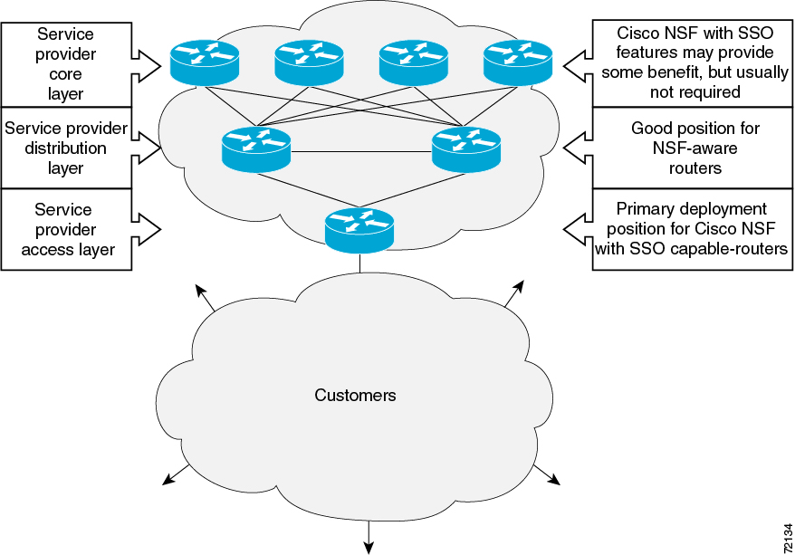
The figure below
illustrates how SSO is typically deployed in service provider networks. In this
example, Cisco NSF with SSO is primarily at the access layer (edge) of the
service provider network. A fault at this point could result in loss of service
for enterprise customers requiring access to the service provider network.
Figure 1. Cisco NSF with SSO Network
Deployment: Service Provider Networks
For Cisco NSF
protocols that require neighboring devices to participate in Cisco NSF, Cisco
NSF-aware software images must be installed on those neighboring distribution
layer devices. Additional network availability benefits might be achieved by
applying Cisco NSF and SSO features at the core layer of your network; however,
consult your network design engineers to evaluate your specific site
requirements.
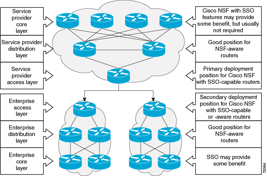
Additional levels of
availability may be gained by deploying Cisco NSF with SSO at other points in
the network where a single point of failure exists. The figure below
illustrates an optional deployment strategy that applies Cisco NSF with SSO at
the enterprise network access layer. In this example, each access point in the
enterprise network represents another single point of failure in the network
design. In the event of a switchover or a planned software upgrade, enterprise
customer sessions would continue uninterrupted through the network.
Figure 2. Cisco NSF with SSO Network
Deployment: Enterprise Networks
Redundancy Modes
Route Processor Redundancy Mode
Router Processor Redundancy (RPR) allows Cisco software to be booted on the standby processor prior to switchover (a cold
boot). In RPR, the standby RP loads a Cisco software image at boot time and initializes itself in standby mode; however, although
the startup configuration is synchronized to the standby RP, system changes are not. In the event of a fatal error on the
active RP, the system switches to the standby processor, which reinitializes itself as the active processor, reads and parses
the startup configuration, reloads all of the line cards, and restarts the system.
Route Processor Synchronization
In networking devices running SSO, both RPs must be running the same configuration so that the standby RP is always ready
to assume control if the active RP fails.
To achieve the benefits of SSO, synchronize the configuration information from the active RP to the standby RP at startup
and whenever changes to the active RP configuration occur. This synchronization occurs in two separate phases:
While the standby RP is booting, the configuration information is synchronized in bulk from the active RP to the standby
RP.
When configuration or state changes occur, an incremental synchronization is conducted from the active RP to the standby
RP.
Bulk Synchronization During Initialization
When a system with SSO is initialized, the active RP performs a chassis discovery (discovery of the number and type of line
cards and fabric cards, if available, in the system) and parses the startup configuration file.
The active RP then synchronizes this data to the standby RP and instructs the standby RP to complete its initialization.
This method ensures that both RPs contain the same configuration information.
Even though the standby RP is fully initialized, it interacts only with the active RP to receive incremental changes to the
configuration files as they occur. Executing CLI commands on the standby RP is not supported.
During system startup, the startup configuration file is copied from the active RP to the standby RP. Any existing startup
configuration file on the standby RP is overwritten. The startup configuration is a text file stored in the NVRAM of the RP.
It is synchronized whenever you perform the following operations:
The command
copysystem:running-confignvram:startup-config is used.
The command
copyrunning-configstartup-config is used.
The command
writememory is used.
The command
copyfilenamenvram:startup-config is used.
SNMP SET of MIB variable ccCopyEntry in CISCO_CONFIG_COPY MIB is used.
System configuration is saved using the
reload command.
System configuration is saved following entry of a forced switchover command.
Incremental Synchronization
After both RPs are fully initialized, any further changes to the running configuration or active RP states are synchronized
to the standby RP as they occur. Active RP states are updated as a result of processing protocol information, external events
(such as the interface becoming up or down), or user configuration commands (using Cisco IOS commands or Simple Network Management
Protocol [SNMP]) or other internal events.
Changes to the running configuration are synchronized from the active RP to the standby RP. In effect, the command is run
on both the active and the standby RP.
Configuration changes caused by an SNMP set operation are synchronized on a case-by-case basis. Only two SNMP configuration
set operations are supported:
shutandno-shut (of an interface)
linkup/downtrapenable/disable
Routing and forwarding information is synchronized to the standby RP:
State changes for SSO-aware protocols (ATM, Frame Relay, PPP, High-Level Data Link Control [HDLC]) or applications (SNMP)
are synchronized to the standby RP.
Cisco Express Forwarding (CEF) updates to the Forwarding Information Base (FIB) are synchronized to the standby RP.
Chassis state changes are synchronized to the standby RP. Changes to the chassis state due to line card insertion or removal
are synchronized to the standby RP.
Changes to the line card states are synchronized to the standby RP. Line card state information is initially obtained during
bulk synchronization of the standby RP. Following bulk synchronization, line card events, such as whether the interface is
up or down, received at the active processor are synchronized to the standby RP.
The various counters and statistics maintained in the active RP are not synchronized because they may change often and because
the degree of synchronization they require is substantial. The volume of information associated with statistics makes synchronizing
them impractical.
Not synchronizing counters and statistics between RPs may create problems for external network management systems that monitor
this information.
Switchover Operation
Switchover Conditions
An automatic or manual switchover may occur under the following conditions:
A fault condition that causes the active RP to crash or reboot--automatic switchover
The active RP is declared dead (not responding)--automatic switchover
The command is invoked--manual switchover
The user can force the switchover from the active RP to the standby RP by using a CLI command. This manual procedure allows
for a graceful or controlled shutdown of the active RP and switchover to the standby RP. This graceful shutdown allows critical
cleanup to occur.
Note
This procedure should not be confused with the graceful shutdown procedure for routing protocols in core routers--they are
separate mechanisms.
Caution
The SSO feature introduces a number of new command and command changes, including commands to manually cause a switchover.
The
reload command does not cause a switchover. The
reload command causes a full reload of the box, removing all table entries, resetting all line cards, and interrupting nonstop forwarding.
Switchover Time
The time required by the device to switch over from the active RP to the standby RP varies by platform:
Although the newly active processor takes over almost immediately following a switchover, the time required for the device
to begin operating again in full redundancy (SSO) mode can be several minutes, depending on the platform. The length of time
can be due to a number of factors including the time needed for the previously active processor to obtain crash information,
load code and microcode, and synchronize configurations between processors and line protocols and Cisco NSF-supported protocols.
Core Dump Operation
In networking devices that support SSO, the newly active primary processor runs the core dump operation after the switchover
has taken place. Not having to wait for dump operations effectively decreases the switchover time between processors.
Following the switchover, the newly active RP will wait for a period of time for the core dump to complete before attempting
to reload the formerly active RP. The time period is configurable. For example, on some platforms an hour or more may be required
for the formerly active RP to perform a coredump, and it might not be site policy to wait that much time before resetting
and reloading the formerly active RP. In the event that the core dump does not complete within the time period provided, the
standby is reset and reloaded regardless of whether it is still performing a core dump.
The core dump process adds the slot number to the core dump file to identify which processor generated the file content.
Note
Core dumps are generally useful only to your technical support representative. The core dump file, which is a very large binary
file, must be transferred using the TFTP, FTP, or remote copy protocol (rcp) server and subsequently interpreted by a Cisco
Technical Assistance Center (TAC) representative that has access to source code and detailed memory maps.
Virtual Template Manager for SSO
The virtual template manager feature for SSO provides virtual access interfaces for sessions that are not HA-capable and are
not synchronized to the standby router. The virtual template manager uses a redundancy facility (RF) client to allow the synchronization
of the virtual interfaces in real time as they are created.
The virtual databases have instances of distributed FIB entries on line cards. Line cards require synchronization of content
and timing in all interfaces to the standby processor to avoid incorrect forwarding. If the virtual access interface is not
created on the standby processor, the interface indexes will be corrupted on the standby router and line cards, which will
cause problems with forwarding.
SSO-Aware Protocols and Applications
SSO-supported line protocols and applications must be SSO-aware. A feature or protocol is SSO-aware if it maintains, either
partially or completely, undisturbed operation through an RP switchover. State information for SSO-aware protocols and applications
is synchronized from active to standby to achieve stateful switchover for those protocols and applications.
The dynamically created state of SSO-unaware protocols and applications is lost on switchover and must be reinitialized and
restarted on switchover.
SSO-aware applications are either platform-independent, such as in the case of line protocols or platform-dependent (such
as line card drivers). Enhancements to the routing protocols (Cisco Express Forwarding, Open Shortest Path First, and Border
Gateway Protocol [BGP]) have been made in the SSO feature to prevent loss of peer adjacency through a switchover; these enhancements
are platform-independent.
Line Protocols
SSO-aware line protocols synchronize session state information between the active and standby RPs to keep session information
current for a particular interface. In the event of a switchover, session information need not be renegotiated with the peer.
During a switchover, SSO-aware protocols also check the line card state to learn if it matches the session state information.
SSO-aware protocols use the line card interface to exchange messages with network peers in an effort to maintain network connectivity.
Frame Relay and Multilink Frame Relay Stateful Switchover
With stateful switchover, Frame Relay and Multilink Frame Relay dynamic state information is synchronized between the active
RP and standby RP. Thus when the active RP fails, the standby RP can take over without spending excessive time relearning
the dynamic state information, and forwarding devices can continue to forward packets with only a few seconds of interruption
(less on some platforms).
Permanent Virtual Circuits
For Frame Relay and Multilink Frame Relay to support forwarding during and after switchover, Frame Relay PVCs must remain
up not only within the networking device, but also within the Frame Relay network.
In many cases the networking devices are connected to a switch, rather than back-to-back to another networking device, and
that switch is not running Cisco software. The virtual circuit state is dependent on line state. PVCs are down when the line
protocol is down. PVCs are up when the line protocol is up and the PVC status reported by the adjacent switch is active.
On point-to-point subinterfaces, or when static mappings are configured, Inverse ARP need not run. In cases where dynamic
address mapping is used, an Inverse ARP protocol exchange determines the protocol address to data-link connection identifier
(DLCI) mapping for the PVC. This exchange occurs as soon as the multipoint PVC makes the transition to active. If the exchange
fails for some reason, for example, the remote networking device may drop the Inverse ARP request if it has not yet seen the
PVC transition to active--any outstanding requests are run off a timer, with a default of 60 seconds.
Keepalive Messages
A crucial factor in maintaining PVCs is the delivery of Local Management Interface (LMI) protocol messages (keepalives) during
switchover. This keepalive mechanism provides an exchange of information between the network server and the switch to verify
that data is flowing.
If a number of consecutive LMI keepalives messages are lost or in error, the adjacent Frame Relay device declares the line
protocol down and all PVCs on that interface are declared down within the Frame Relay network and reported as such to the
remote networking device. The speed with which a switchover occurs is crucial to avoid the loss of keepalive messages.
The line protocol state depends on the Frame Relay keepalive configuration. With keepalives disabled, the line protocol is
always up as long as the hardware interface is up. With keepalives enabled, LMI protocol messages are exchanged between the
networking device and the adjacent Frame Relay switch. The line protocol is declared up after a number of consecutive successful
LMI message exchanges.
The line protocol must be up according to both the networking device and the switch. The default number of exchanges to bring
up the line protocol is implementation-dependent: Three is suggested by the standards; four is used on a Cisco Frame Relay
switch, taking 40 seconds at the default interval of 10 seconds; and two is used on a Cisco networking device acting as a
switch or when connected back-to-back. This default number could be extended if the LMI “autosense” feature is being used
while the LMI type expected on the switch is determined. The number of exchanges is configurable, although the switch and
router may not have the same owner.
The default number of lost messages or errors needed to bring down the line is three (two on a Cisco router). By default,
if a loss of two messages is detected in 15 to 30 seconds, then a sequence number or LMI type error in the first message from
the newly active RP takes the line down.
If a line goes down, consecutive successful LMI protocol exchanges (default of four over 40 seconds on a Cisco Frame Relay
switch; default of two over 20 seconds on a Cisco device) will bring the line back up again.
PPP and Multilink PPP
Stateful Switchover
With stateful
switchover, specific PPP state information is synchronized between the active
RP and standby RP. Thus when the active RP fails, the standby RP can take over
without spending excessive time renegotiating the setup of a given link. As
long as the physical link remains up, forwarding devices can continue to
forward packets with only a few seconds of interruption (less on some
platforms). Single-link PPP and Multilink PPP (MLP) sessions are maintained
during RP switchover for IP connections only.
PPP and MLP support
many Layer 3 protocols such as IPX and IP. Only IP links are supported in SSO.
Links supporting non IP traffic will momentarily renegotiate and resume
forwarding following a switchover. IP links will forward IP traffic without
renegotiation.
A key factor in
maintaining PPP session integrity during a switchover is the use of keepalive
messages. This keepalive mechanism provides an exchange of information between
peer interfaces to verify data and link integrity. Depending on the platform
and configuration, the time required for switchover to the standby RP might
exceed the keepalive timeout period. PPP keepalive messages are started when
the physical link is first brought up. By default, keepalive messages are sent
at 10-second intervals from one PPP interface to the other PPP peer.
If five consecutive
keepalive replies are not received, the PPP link would be taken down on the
newly active RP. Caution should be used when changing the keepalive interval
duration to any value less than the default setting.
Only in extremely
rare circumstances could the RP switchover time exceed the default 50-second
keepalive duration. In the unlikely event this time is exceeded, the PPP links
would renegotiate with the peers and resume IP traffic forwarding.
Note
PPP and MLP are not
configurable and run by default on networking devices configured with SSO.
HDLC Stateful
Switchover
With stateful
switchover, High-Level Data Link Control (HDLC) synchronizes the line protocol
state information. Additionally, the periodic timer is restarted for interfaces
that use keepalive messages to verify link integrity. Link state information is
synchronized between the active RP and standby RP. The line protocols that were
up before the switchover remain up afterward as long as the physical interface
remains up. Line protocols that were down remain down.
A key factor in
maintaining HDLC link integrity during a switchover is the use of keepalive
messages. This keepalive mechanism provides an exchange of information between
peer interfaces to verify data is flowing. HDLC keepalive messages are started
when the physical link is first brought up. By default, keepalive messages are
sent at 10-second intervals from one HDLC interface to the other.
HDLC waits at least
three keepalive intervals without receiving keepalive messages, sequence number
errors, or a combination of both before it declares a line protocol down. If
the line protocol is down, SSO cannot support continuous forwarding of user
session information in the event of a switchover.
Note
HDLC is not
configurable and runs by default on networking devices configured with SSO.
Quality of Service
The modular QoS CLI (MQS)-based QoS feature maintains a database of various objects created by the user, such as those used
to specify traffic classes, actions for those classes in traffic policies, and attachments of those policies to different
traffic points such as interfaces. With SSO, QoS synchronizes that database between the primary and secondary RP.
IPv6 Support for Stateful Switchover
IPv6 neighbor discovery supports SSO using Cisco Express Forwarding. When switchover occurs, the Cisco Express Forwarding
adjacency state, which is checkpointed, is used to reconstruct the neighbor discovery cache.
Line Card Drivers
Platform-specific line card device drivers are bundled with the Cisco software image for SSO and are correct for a specific
image, meaning they are designed to be SSO-aware.
Line cards used with the SSO feature periodically generate status events that are forwarded to the active RP. Information
includes the line up or down status, and the alarm status. This information helps SSO support bulk synchronization after standby
RP initialization and support state reconciliation and verification after a switchover.
Line cards used with the SSO feature also have the following requirements:
Line cards must not reset during switchover.
Line cards must not be reconfigured.
Subscriber sessions may not be lost.
Note
The standby RP communicates only with the active RP, never with the line cards. This function helps to ensure that the active
and standby RP always have the same information.
APS
SSO support allow the automatic protection switching (APS) state to be preserved in the event of failover.
Routing Protocols and Nonstop
Forwarding
Cisco nonstop
forwarding (NSF) works with SSO to minimize the amount of time a network is
unavailable to its users following a switchover. When a networking device
restarts, all routing peers of that device usually detect that the device went
down and then came back up. This down-to-up transition results in what is
called a “routing flap,” which could spread across multiple routing domains.
Routing flaps caused by routing restarts create routing instabilities, which
are detrimental to the overall network performance. Cisco NSF helps to suppress
routing flaps, thus improving network stability.
Cisco NSF allows for
the forwarding of data packets to continue along known routes while the routing
protocol information is being restored following a switchover. With Cisco NSF,
peer networking devices do not experience routing flaps. Data traffic is
forwarded through intelligent line cards while the standby RP assumes control
from the failed active RP during a switchover. The ability of line cards to
remain up through a switchover and to be kept current with the FIB on the
active RP is key to Cisco NSF operation.
A key element of
Cisco NSF is packet forwarding. In Cisco networking devices, packet forwarding
is provided by Cisco Express Forwarding. Cisco Express Forwarding maintains the
FIB, and uses the FIB information that was current at the time of the
switchover to continue forwarding packets during a switchover. This feature
eliminates downtime during the switchover.
Cisco NSF supports
the BGP, IS-IS, and OSPF routing protocols. In general, these routing protocols
must be SSO-aware to detect a switchover and recover state information
(converge) from peer devices. Each protocol depends on Cisco Express Forwarding
to continue forwarding packets during switchover while the routing protocols
rebuild the Routing Information Base (RIB) tables.
Network Management
Network management support for SSO is provided through the synchronization of specific SNMP data between the active and standby
RPs. From a network management perspective, this functionality helps to provide an uninterrupted management interface to the
network administrator.
Note
Synchronization of SNMP data between RPs is available only when the networking device is operating in SSO mode.
SSO for Circuit Emulation Services
SSO for circuit emulation services (CES) for TDM pseudowires provides the ability to switch an incoming DS1/T1/E1 on one SPA
to another SPA on same SIP or onto a different SIP.
Configures automatic synchronization of Frame Relay LMI sequence numbers between the active RP and the standby RP.
Verifying SSO Configuration
SUMMARY STEPS
enable
showredundancy [clients |
counters |
history |
switchoverhistory |
states]
showredundancystates
DETAILED STEPS
Command or Action
Purpose
Step 1
enable
Example:
Router> enable
Enables privileged EXEC mode.
Enter your password if prompted.
Step 2
showredundancy [clients |
counters |
history |
switchoverhistory |
states]
Example:
Router# show redundancy
Displays SSO configuration information.
Step 3
showredundancystates
Example:
Router# show redundancy states
Verifies that the device is running in SSO mode.
Troubleshooting Stateful
Switchover
The standby RP was
reset, but there are no messages describing what happened--To display a log of
SSO events and clues as to why a switchover or other event occurred, enter the
showredundancyhistory command on the newly active RP.
The show
redundancy states command shows an operating mode that is different than what
is configured on the networking device--On certain platforms the output of the
showredundancystates command displays the actual operating
redundancy mode running on the device, and not the configured mode as set by
the platform. The operating mode of the system can change depending on system
events. For example, SSO requires that both RPs on the networking device be
running the same software image; if the images are different, the device will
not operate in SSO mode, regardless of its configuration.
Reloading the
device disrupts SSO operation--The SSO feature introduces a number of commands,
including commands to manually cause a switchover. The reload command is not an
SSO command. This command causes a full reload of the box, removing all table
entries, resetting all line cards, and thereby interrupting network traffic
forwarding. To avoid reloading the box unintentionally, use the
redundancyforce-switchover command.
During a software upgrade,
the networking device appears to be in a mode other than SSO--During the
software upgrade process, the show redundancy command indicates that the device
is running in a mode other than SSO.
This is normal
behavior. Until the FSU procedure is complete, each RP will be running a
different software version.
You can enter ROM
monitor mode by restarting the router and then pressing the Break key or
issuing a
sendbreak command from a telnet session during the
first 60 seconds of startup.The send break function can be useful for
experienced users or for users under the direction of a Cisco Technical
Assistance Center (TAC) representative to recover from certain system problems
or to evaluate the cause of system problems.
showredundancy [clients |
counters |
debug-log |
handover |
history |
switchoverhistory |
states |
inter-device]
Example:
Router# show redundancy
Displays the
redundancy configuration mode of the RP. Also displays information about the
number of switchovers, system uptime, processor uptime, and redundancy state,
and reasons for any switchovers.
No new or modified RFCs are supported by this feature.
--
Technical Assistance
Description
Link
The Cisco Support and Documentation website provides online resources to download documentation, software, and tools. Use
these resources to install and configure the software and to troubleshoot and resolve technical issues with Cisco products
and technologies. Access to most tools on the Cisco Support and Documentation website requires a Cisco.com user ID and password.


 Feedback