Radio Aware Routing and Dynamic Link Exchange Protocol

This chapter contains the following sections:

Overview of Radio Aware Routing

Introduction

Relief workers, soldiers, public safety personnel, and others need the right information, in the right place, at the right time, wherever they are located. Mobile ad hoc networks are emerging to address these needs. The IETF request for comment, RFC RFC5578, defines a PPP-over-Ethernet (PPPoE) based mechanism for integrating IP routers and mobile radios in ad hoc networks, enabling faster convergence, more efficient route selection, and better performance for delaysensitive traffic.

Radio-Aware Routing (RAR) is a mechanism that uses radios to interact with the routing protocol OSPFv3/EIGRP to signal the appearance, disappearance, and link conditions of one-hop routing neighbors.

In large mobile networks, connections to the routing neighbors are often interrupted due to distance and radio obstructions. When these signals do not reach the routing protocols, protocol timers are used to update the status of a neighbor. Routing protocols have lengthy timers, which is not recommended in mobile networks.

The RAR feature is supported on the Cisco ESR6300 Embedded Series Router.

Mobile Ad Hoc Networking (MANET)

Mobile ad hoc networks are emerging as a means for delivering the benefits of IP networking to users operating beyond the reach of a fixed network. In ad hoc networks, mobile nodes associate on an extemporaneous or ad hoc basis. Ad hoc networks have numerous distinguishing characteristics when compared to conventional networking solutions:

  • Self-forming — Nodes that come within radio range of each other can establish a network association without any pre-configuration or manual intervention.

  • Self-healing — Nodes can join or leave rapidly without affecting operation of the remaining nodes.

  • No infrastructure — In an ad hoc network, mobile nodes form their own network, and essentially become their own infrastructure.

  • Peer to peer — Traditional networks typically support end systems operating in client-server mode. In an ad hoc network, mobile nodes can communicate and exchange information without prior arrangement and without reliance on centralized resources.

  • Predominantly wireless — Historically networks have been mostly wired, and enhanced or extended through wireless access. The ad hoc environment is essentially wireless, but can be extended to support wired resources.

  • Highly dynamic — Mobile nodes are in continuous motion and ad hoc networking topologies are constantly changing.

Collectively, these characteristics will enable ad hoc networks to deliver timely information to a new and underserved class of users. Ad hoc networking solutions can be applied to virtually any scenario that involves a cadre of highly mobile users or platforms (which may include stationary devices as well), a strong need to share IP-based information, and an environment in which fixed infrastructure is impractical, impaired, or impossible.

A Real-World Problem Description

Consider the following diagram:

The above network is a voice, video, data network between moving vehicles that consists of both ground and air vehicles, hence the network is mobile and it is a peer to peer mesh that changes as topographical obstructions are encountered. This is where we get the term mobile ad hock network or MANET for short.

In the scenario in the drawing, all 4 trucks always have connectivity with the helicopters that are flying over the same road. The two helicopters always have line of sight and will always have a connection between each other. The trucks may even be able to connect to the other helicopter or a truck on the opposite road when conditions are favorable.

Here we see that the path between trucks 1 and 3 are completely blocked. The path between Truck 2 and 4 is about to be blocked.

Our existing routing protocols such as OSPFv3 and EIGRP need to adjust its path metrics very quickly to maintain a cohesive operational network. The routing protocol also needs a way to get that information from the radios and that requires a radio to router protocol that is delivered by Cisco Radio Aware Routing in the form of two open protocols:

  • PPP over Ethernet (PPPoE)

  • Dynamic Link Exchange Protocol (DLEP)

Both protocols are discussed later in this document.

Benefits of Radio Aware Routing

The Radio Aware Routing feature offers the following benefits:

  • Provides faster network convergence through immediate recognition of changes.

  • Enables routing for failing or fading radio links.

  • Allows easy routing between line-of-sight and non-line-of-sight paths.

  • Provides faster convergence and optimal route selection so that delay-sensitive traffic, such as voice and video, is not disrupted

  • Provides efficient radio resources and bandwidth usage.

  • Reduces impact on the radio links by performing congestion control in the router.

  • Allows route selection based on radio power conservation.

  • Enables decoupling of the routing and radio functionalities.

  • Provides simple Ethernet connection to RFC 5578 and DLEP compliant radios.

Restrictions and Limitations

The Radio Aware Routing and DLEP features have the following restrictions and limitations:

  • Multicast traffic is not supported with DLEP, but is supported with PPPOE.

  • DLEP does not support IPv6

  • Cisco High Availability (HA) technology is not supported.

  • Requires the Network Advantage license.


Note


There is a condition that exists with DLEP that is not unique to the ESR6300. An ARP which has been learned on a VMI does not get deleted when the mapped physical interface goes down.

Note


Previous releases of IOS XE offered support for IPv4 unicast traffic over an IPv4 DLEP session. IOS XE 17.12.1a provides support for IPv6 unicast, IPv4 multicast and IPv6 multicast over an IPv4 DLEP. See the DLEP IPv6 Unicastsection.

Performance

The Radio Aware Routing feature has the ability to support a maximum of 10 neighbors per radio or VMI interface, and a total of 30 to 40 neighbors.

System Components

The Radio Aware Routing (RAR) feature is implemented using the MANET (Mobile adhoc network) infrastructure comprising of different components such as PPPoE, Virtual multipoint interface (VMI), QoS, routing protocol interface and RAR protocols.

Point-to-Point Protocol over Ethernet PPPoE or PPPoE

PPPoE is a well-defined communication mechanism between the client and the server. In the RAR implementation, radio takes the role of the PPPoE client and router takes the role of the PPPoE server. This allows a loose coupling of radio and router, while providing a well-defined and predictable communication mechanism.

As PPPoE is a session or a connection oriented protocol, it extends the point-to-point radio frequency (RF) link from an external radio to an IOS router.

PPPoE Extensions

PPPoE extensions are used when the router communicates with the radio. In the Cisco IOS implementation of PPPoE, each individual session is represented by virtual access interface (connectivity to a radio neighbor) on which, QoS can be applied with these PPPoE extensions.

RFC5578 provides extensions to PPPoE to support credit-based flow control and session-based real time link metrics, which are very useful for connections with variable bandwidth and limited buffering capabilities (such as radio links).

Virtual Multipoint Interface (VMI)

Though PPPoE Extensions provides most of the setup to communicate between a router and a radio, VMI addresses the need to manage and translate events that higher layers (example, routing protocols) consume. In addition, VMI operates in the Bypass mode.

In Bypass mode, every Virtual Access Interface (VAI) representing a radio neighbor is exposed to routing protocols OSPFv3 and EIGRP, so that, the routing protocol directly communicates with the respective VAI for both unicast and multicast routing protocol traffic.


Note


DLEP only supports aggregate mode. The preferred mode for PPPOE is bypass.

In Aggregate mode, VMI is exposed to the routing protocols (OSPF) so that the routing protocols can leverage VMI for their optimum efficiency. When the network neighbors are viewed as a collection of networks on a point-to-multipoint link with broadcast and multicast capability at VMI, VMI helps in aggregating the multiple virtual access interfaces created from PPPoE. VMI presents a single multi access layer 2 broadcast capable interface. The VMI layer re-directs unicast routing protocol traffic to the appropriate P2P link (Virtual-Access interface), and replicates any Multicast/Broadcast traffic that needs to flow. Since the routing protocol communicates to a single interface, the size of the topology database is reduced, without impacting the integrity of the network.

Radio Aware Routing Topology

This section provides a high level description on how RAR, MANETs, and PPPoE work together.

About MANETs

Mobile Ad Hoc Networks (MANETs) for device-to-radio communications address the challenges faced when merging IP routing and mobile radio communications in ad hoc networking applications.

Through the device-to-radio link, the radio can inform the device immediately when a node joins or leaves, and this enables the device to recognize topology changes more quickly than if it had to rely on timers. Without this link-status notification from the radio, the device would likely time out while waiting for traffic. The link-status notification from the radio enables the device to respond faster to network topology changes. Metric information regarding the quality of a link is passed between the device and radio, enabling the device to more intelligently decide on which link to use.

With the link-status signaling provided by the device-to-radio link, applications such as voice and video work better because outages caused by topology changes are reduced or eliminated. Sessions are more stable and remain active longer.

Cross-layer feedback for device-to-radio integration of Radio-Aware Routing (RAR) takes advantage of the functions defined in RFC 5578. The RFC 5578 is an Internet Engineering Task Force (IETF) standard that defines PPP over Ethernet (PPPoE) extensions for Ethernet-based communications between a device and a mobile radio, that operates in a variable-bandwidth environment and has limited buffering capabilities. These extensions provide a PPPoE session-based mechanism for sharing radio network status such as link-quality metrics and establishing flow control between a device and an RAR-compliant radio.

An RAR-compliant radio initiates a Layer 2 PPPoE session with its adjacent device on behalf of every device and radio neighbor discovered in the network. These Layer 2 sessions are the means by which radio network status for each neighbor link is reported to the device. The radio establishes the correspondence between each PPPoE session and each link to a neighbor.

PPPoE Interfaces for Mobile Radio Communications

The Mobile Ad Hoc Network (MANET) implementation uses PPP over Ethernet (PPPoE) sessions to enable intranodal communications between a device and its partner radio. Each radio initiates the PPPoE session as soon as the radio establishes a radio link to another radio. After the PPPoE sessions are active, a PPP session is established end-to-end (device-to-device). This is duplicated each time a radio establishes a new radio link. The virtual multipoint interface (VMI) on the device can aggregate multiple PPPoE sessions and multiplex them to look like a single interface to the routing processes. Underneath the VMI are virtual access interfaces that are associated with each of the PPP and PPPoE connections.

A PPPoE session is established between a device and a radio on behalf of every other device and radio neighbor located in the MANET. These Layer 2 sessions are the means by which radio network status gets reported to the Layer 3 processes in the device. The figure below shows the PPPoE session exchange between mobile devices and directional radios in a MANET network.

Figure 1. PPPoE Session Exchange Between Mobile Devices and Directional Radios

This capability requires that a Radio-Aware Routing (RAR)-compliant radio be connected to a device through Ethernet. The device always considers the Ethernet link to be up. If the radio side of the link goes down, the device waits until a routing update timeout occurs to declare the route down and then updates the routing table. The figure below shows a simple device-to-radio link topology.

Figure 2. Device-to-Radio Link

Neighbor Up and Down Signaling

Mobile Ad Hoc Networks (MANETs) are highly dynamic environments. Nodes might move into, or out of, radio range at a fast pace. Each time a node joins or leaves, the network topology must be logically reconstructed by the devices. Routing protocols normally use timer-driven hello messages or neighbor timeouts to track topology changes, but MANETs reliance on these mechanisms can result in unacceptably slow convergence.

The neighbor up/down signaling capability provides faster network convergence by using link-status signals generated by the radio. The radio notifies the device each time a link to another neighbor is established or terminated by the creation and termination of PPP over Ethernet (PPPoE) sessions. In the device, the routing protocols (Open Shortest Path First version 3 [OSPFv3] or Enhanced Interior Gateway Routing Protocol [EIGRP]) respond immediately to these signals by expediting formation of a new adjacency (for a new neighbor) or tearing down an existing adjacency (if a neighbor is lost). For example, if a vehicle drives behind a building and loses its connection, the device immediately senses the loss and establishes a new route to the vehicle through neighbors that are not blocked. This high-speed network convergence is essential for minimizing dropped voice calls and disruptions to video sessions.

When virtual multipoint interfaces (VMIs) with PPPoE are used and a partner node has left or a new one has joined, the radio informs the device immediately of the topology change. Upon receiving the signal, the device immediately declares the change and updates the routing tables. The signaling capability provides these advantages:

  • Reduces routing delays and prevents applications from timing out

  • Enables network-based applications and information to be delivered reliably and quickly over directional radio links

  • Provides faster convergence and optimal route selection so that delay-sensitive traffic such as voice and video are not disrupted

  • Reduces impact on radio equipment by minimizing the need for internal queueing and buffering

  • Provides consistent quality of service for networks with multiple radios

The messaging allows for flexible rerouting when necessary because of these factors:

  • Fading of the radio links

  • Congestion of the radio links

  • Radio link power fade

  • Utilization of the radio

The figure below shows the signaling sequence that occurs when radio links go up and down:

Figure 3. Up and Down Signaling Sequence

PPPoE Credit-based and Metric-based Scaling and Flow Control

Each radio initiates a PPP over Ethernet (PPPoE) session with its local device as soon as the radio establishes a link to another radio. Once the PPPoE sessions are active for each node, a PPP session is then established end-to-end (device-to-device). This process is duplicated each time a radio establishes a new link.

The carrying capacity of each radio link might vary due to location changes or environmental conditions, and many radio transmission systems have limited buffering capabilities. To minimize the need for packet queueing in the radio, PPPoE protocol extensions enable the device to control traffic buffering in congestion situations. Implementing flow-control on these device-to-radio sessions allows use of quality of service (QoS) features such as fair queueing.

The flow-control solution utilizes a credit-granting mechanism documented in RFC 5578. When the PPPoE session is established, the radio can request a flow-controlled session. If the device acknowledges the request, all subsequent traffic must be flow controlled. If a flow-control session is requested and cannot be supported by the device, the session is terminated. Typically, both the radio and the device initially grant credits during session discovery. Once a device exhausts its credits, it must stop sending until additional credits are granted. Credits can be added incrementally over the course of a session.

Metrics scaling is used with high-performance radios that require high-speed links. The radio can express the maximum and current data rates with different scaler values. Credit scaling allows a radio to change the default credit grant (or scaling factor) of 64 bytes to its default value. You can display the maximum and current data rates and the scalar value set by the radio in the show vmi neighbor detail command output.

QoS Provisioning on PPPoE Extension Session

The following example describes QoS provisioning on PPPoE extension session:

policy-map rar_policer
 class class-default
  police 10000 2000 1000 conform-action transmit  exceed-action drop  violate-action drop
policy-map rar_shaper
 class class-default
  shape average percent 1
 
interface Virtual-Template2
 ip address 92.92.2.1 255.255.255.0
 no peer default ip address
 no keepalive
 service-policy input rar_policer
end

Example: Configuring the RAR Feature in Bypass Mode

The following example is an end-to-end configuration of RAR in the bypass mode:


Note


Before you begin the RAR configuration, you must first configure the subscriber authorization enable command to bring up the RAR session. Without enabling authorization, the Point-to-Point protocol does not recognize this as a RAR session and may not tag manet_radio in presentation of a PPPoE Active Discovery Initiate (PADI). By default, bypass mode does not appear in the configuration. It appears only if the mode is configured as bypass.

Configure a Service for RAR

policy-map type service rar-lab 
 pppoe service manet_radio //note: Enter the pppoe service policy name as manet_radio
!
Configure Broadband
bba-group pppoe VMI2
 virtual-template 2
service profile rar-lab 
!
interface GigabitEthernet0/0/0
 description Connected to Client1
  negotiation auto
  pppoe enable group VMI2
!

Configuration in Bypass Mode

  • IP Address Configured under Virtual-Template Explicitly


    interface Virtual-Template2
    ip address 192.168.90.3 255.255.255.0
    no ip redirects
    peer default ip address pool PPPoEpool2
    ipv6 enable
    ospfv3 1 network manet
    ospfv3 1 ipv4 area 0
    ospfv3 1 ipv6 area 0
    no keepalive
    service-policy input rar_policer Or/And
    service-policy output rar_shaper
    
  • VMI Unnumbered Configured under Virtual Template

    
    interface Virtual-Template2
    ip unnumbered vmi2
    no ip redirects
    peer default ip address pool PPPoEpool2 
    ipv6 enable
    ospfv3 1 network manet
    ospfv3 1 ipv4 area 0
    ospfv3 1 ipv6 area 0
    no keepalive
    service-policy input rar_policer Or/And
    service-policy output rar_shaper
    

Configure the Virtual Multipoint Interface in Bypass Mode


interface vmi2 //configure the virtual multi interface
ip address 192.168.2.1 255.255.255.0
physical-interface GigabitEthernet0/0/0
mode bypass     

Configure OSPF Routing

router ospfv3 1
 router-id 1.1.1.1
!
 address-family ipv4 unicast
  redistribute connected metric 1 metric-type 1
  log-adjacency-changes
 exit-address-family
 !
 address-family ipv6 unicast
  redistribute connected metric-type 1
  log-adjacency-changes
 exit-address-family
!
ip local pool PPPoEpool2 192.168.2.3 192.168.2.254

Verifying RAR Session Details

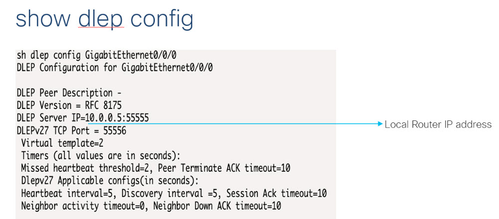
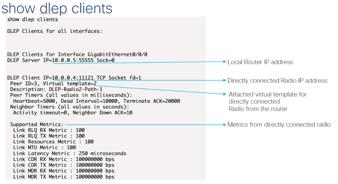
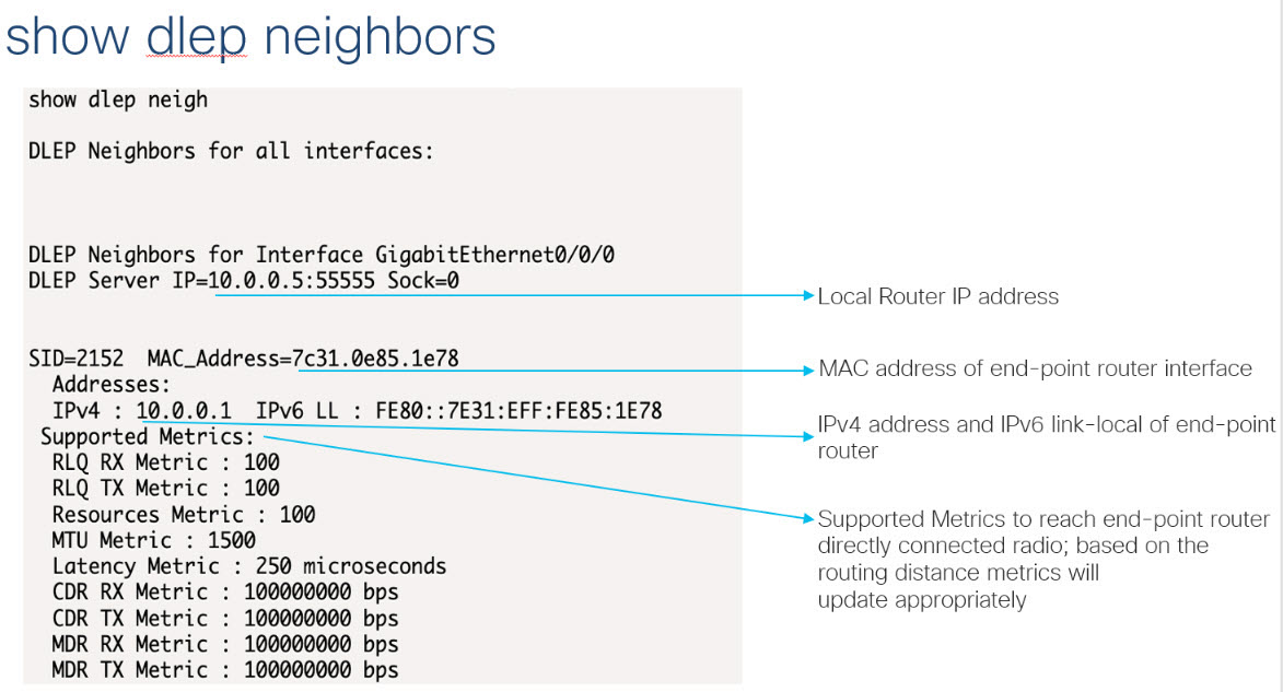
To retrieve RAR session details, use the following show commands:

Router#show pppoe session packets all 
Total PPPoE sessions 2                                                        

session id: 9
local MAC address: 006b.f10e.a5e0, remote MAC address: 0050.56bc.424a
virtual access interface: Vi2.1, outgoing interface: Gi0/0/0         
    1646 packets sent, 2439363 received                              
    176216 bytes sent, 117250290 received                            

PPPoE Flow Control Stats
 Local Credits: 65535   Peer Credits: 65535   Local Scaling Value 64 bytes
 Credit Grant Threshold: 28000    Max Credits per grant: 65535            
 Credit Starved Packets: 0                                                
 PADG xmit Seq Num: 32928     PADG Timer index: 0                         
 PADG last rcvd Seq Num: 17313                                            
 PADG last nonzero Seq Num: 17306                                         
 PADG last nonzero rcvd amount: 2                                         
 PADG Timers: (ms)   [0]-1000    [1]-2000    [2]-3000    [3]-4000    [4]-5000 
 PADG xmit: 33308  rcvd: 17313                                                
 PADC xmit: 17313  rcvd: 19709                                                
 In-band credit pkt xmit: 7 rcvd: 2434422                                     
 Last credit packet snapshot                                                  
  PADG xmit: seq_num = 32928, fcn = 0, bcn = 65535                            
  PADC rcvd: seq_num = 32928, fcn = 65535, bcn = 65535
  PADG rcvd: seq_num = 17313, fcn = 0, bcn = 65535
  PADC xmit: seq_num = 17313, fcn = 65535, bcn = 65535
  In-band credit pkt xmit: fcn = 61, bcn = 65533
  In-band credit pkt rcvd: fcn = 0, bcn = 65534
    ==== PADQ Statistics ====
     PADQ xmit: 0  rcvd: 0


session id: 10
local MAC address: 006b.f10e.a5e1, remote MAC address: 0050.56bc.7dcb
virtual access interface: Vi2.2, outgoing interface: Gi0/0/1
    1389302 packets sent, 1852 received
    77869522 bytes sent, 142156 received

PPPoE Flow Control Stats
 Local Credits: 65535   Peer Credits: 65535   Local Scaling Value 64 bytes
 Credit Grant Threshold: 28000    Max Credits per grant: 65535
 Credit Starved Packets: 0
 PADG xmit Seq Num: 18787     PADG Timer index: 0
 PADG last rcvd Seq Num: 18784
 PADG last nonzero Seq Num: 18768
 PADG last nonzero rcvd amount: 2
 PADG Timers: (ms)   [0]-1000    [1]-2000    [2]-3000    [3]-4000    [4]-5000
 PADG xmit: 18787  rcvd: 18784
 PADC xmit: 18784  rcvd: 18787
 In-band credit pkt xmit: 1387764 rcvd: 956
 Last credit packet snapshot
  PADG xmit: seq_num = 18787, fcn = 0, bcn = 65535
  PADC rcvd: seq_num = 18787, fcn = 65535, bcn = 65535
  PADG rcvd: seq_num = 18784, fcn = 0, bcn = 65535
  PADC xmit: seq_num = 18784, fcn = 65535, bcn = 65535
  In-band credit pkt xmit: fcn = 0, bcn = 64222
  In-band credit pkt rcvd: fcn = 0, bcn = 65534
    ==== PADQ Statistics ====
     PADQ xmit: 0  rcvd: 1
Router#show pppoe session packets 
Total PPPoE sessions 2

SID     Pkts-In         Pkts-Out        Bytes-In        Bytes-Out
9       2439391         1651            117252098       176714
10      1858            1389306         142580          77869914
Router#show vmi counters 
Interface vmi2: - Last Clear Time =                               

Input Counts:
  Process Enqueue      =          0 (VMI)
  Fastswitch           =          0      
  VMI Punt Drop:                         
       Queue Full      =          0      

Output Counts:
  Transmit:   
       VMI Process DQ  =       4280
       Fastswitch VA   =          0
       Fastswitch VMI  =          0
  Drops:                           
       Total           =          0
       QOS Error       =          0
       VMI State Error =          0
       Mcast NBR Error =          0
       Ucast NBR Error =          0
Interface vmi3: - Last Clear Time = 

Input Counts:
  Process Enqueue      =          0 (VMI)
  Fastswitch           =          0
  VMI Punt Drop:
       Queue Full      =          0

Output Counts:
  Transmit:
       VMI Process DQ  =       2956
       Fastswitch VA   =          0
       Fastswitch VMI  =          0
  Drops:
       Total           =          0
       QOS Error       =          0
       VMI State Error =          0
       Mcast NBR Error =          0
       Ucast NBR Error =          0
Interface vmi4: - Last Clear Time =

Input Counts:
  Process Enqueue      =          0 (VMI)
  Fastswitch           =          0
  VMI Punt Drop:
       Queue Full      =          0

Output Counts:
  Transmit:
       VMI Process DQ  =          0
       Fastswitch VA   =          0
       Fastswitch VMI  =          0
  Drops:
       Total           =          0
       QOS Error       =          0
       VMI State Error =          0
       Mcast NBR Error =          0
       Ucast NBR Error =          0
Router#
Router#show vmi neighbor details 
1 vmi2 Neighbors
1 vmi3 Neighbors
0 vmi4 Neighbors
2 Total Neighbors

vmi2   IPV6 Address=FE80::21E:E6FF:FE43:F500
       IPV6 Global Addr=::                  
       IPV4 Address=92.92.2.2, Uptime=05:15:01
       Output pkts=89, Input pkts=0           
       No Session Metrics have been received for this neighbor.
       Transport PPPoE, Session ID=9                           
       INTERFACE STATS:                                        
          VMI Interface=vmi2,                                  
             Input qcount=0, drops=0, Output qcount=0, drops=0 
          V-Access intf=Virtual-Access2.1,                     
             Input qcount=0, drops=0, Output qcount=0, drops=0 
          Physical intf=GigabitEthernet0/0/0,                  
             Input qcount=0, drops=0, Output qcount=0, drops=0 

PPPoE Flow Control Stats
 Local Credits: 65535   Peer Credits: 65535   Local Scaling Value 64 bytes
 Credit Grant Threshold: 28000    Max Credits per grant: 65535            
 Credit Starved Packets: 0                                                
 PADG xmit Seq Num: 33038     PADG Timer index: 0                         
 PADG last rcvd Seq Num: 17423                                            
 PADG last nonzero Seq Num: 17420                                         
 PADG last nonzero rcvd amount: 2                                         
 PADG Timers: (ms)   [0]-1000    [1]-2000    [2]-3000    [3]-4000    [4]-5000 
 PADG xmit: 33418  rcvd: 17423                                                
 PADC xmit: 17423  rcvd: 19819                                                
 In-band credit pkt xmit: 7 rcvd: 2434446                                     
 Last credit packet snapshot                                                  
  PADG xmit: seq_num = 33038, fcn = 0, bcn = 65535                            
  PADC rcvd: seq_num = 33038, fcn = 65535, bcn = 65535                        
  PADG rcvd: seq_num = 17423, fcn = 0, bcn = 65535                            
  PADC xmit: seq_num = 17423, fcn = 65535, bcn = 65535                        
  In-band credit pkt xmit: fcn = 61, bcn = 65533                              
  In-band credit pkt rcvd: fcn = 0, bcn = 65534                               
    ==== PADQ Statistics ====                                                 
     PADQ xmit: 0  rcvd: 0                                                    


vmi3   IPV6 Address=FE80::21E:7AFF:FE68:6100
       IPV6 Global Addr=::                  
       IPV4 Address=91.91.91.4, Uptime=05:14:55
       Output pkts=6, Input pkts=0             
       METRIC DATA: Total rcvd=1, Avg arrival rate (ms)=0
          CURRENT: MDR=128000 bps, CDR=128000 bps        
                   Lat=0 ms, Res=100, RLQ=100, load=0    
          MDR      Max=128000 bps, Min=128000 bps, Avg=128000 bps
          CDR      Max=128000 bps, Min=128000 bps, Avg=128000 bps
          Latency  Max=0, Min=0, Avg=0 (ms)
          Resource Max=100%, Min=100%, Avg=100%
          RLQ      Max=100, Min=100, Avg=100
          Load     Max=0%, Min=0%, Avg=0%
       Transport PPPoE, Session ID=10
       INTERFACE STATS:
          VMI Interface=vmi3,
             Input qcount=0, drops=0, Output qcount=0, drops=0
          V-Access intf=Virtual-Access2.2,
             Input qcount=0, drops=0, Output qcount=0, drops=0
          Physical intf=GigabitEthernet0/0/1,
             Input qcount=0, drops=0, Output qcount=0, drops=0

PPPoE Flow Control Stats
 Local Credits: 65535   Peer Credits: 65535   Local Scaling Value 64 bytes
 Credit Grant Threshold: 28000    Max Credits per grant: 65535
 Credit Starved Packets: 0
 PADG xmit Seq Num: 18896     PADG Timer index: 0
 PADG last rcvd Seq Num: 18894
 PADG last nonzero Seq Num: 18884
 PADG last nonzero rcvd amount: 2
 PADG Timers: (ms)   [0]-1000    [1]-2000    [2]-3000    [3]-4000    [4]-5000
 PADG xmit: 18896  rcvd: 18894
 PADC xmit: 18894  rcvd: 18896
 In-band credit pkt xmit: 1387764 rcvd: 961
 Last credit packet snapshot
  PADG xmit: seq_num = 18896, fcn = 0, bcn = 65535
  PADC rcvd: seq_num = 18896, fcn = 65535, bcn = 65535
  PADG rcvd: seq_num = 18894, fcn = 0, bcn = 65535
  PADC xmit: seq_num = 18894, fcn = 65535, bcn = 65535
  In-band credit pkt xmit: fcn = 0, bcn = 64222
  In-band credit pkt rcvd: fcn = 0, bcn = 65534
    ==== PADQ Statistics ====
     PADQ xmit: 0  rcvd: 1
Router#show vmi neighbor details vmi 2
              1 vmi2 Neighbors      

vmi2   IPV6 Address=FE80::21E:E6FF:FE43:F500
       IPV6 Global Addr=::
       IPV4 Address=92.92.2.2, Uptime=05:16:03
       Output pkts=89, Input pkts=0
       No Session Metrics have been received for this neighbor.
       Transport PPPoE, Session ID=9
       INTERFACE STATS:
          VMI Interface=vmi2,
             Input qcount=0, drops=0, Output qcount=0, drops=0
          V-Access intf=Virtual-Access2.1,
             Input qcount=0, drops=0, Output qcount=0, drops=0
          Physical intf=GigabitEthernet0/0/0,
             Input qcount=0, drops=0, Output qcount=0, drops=0

PPPoE Flow Control Stats
 Local Credits: 65535   Peer Credits: 65535   Local Scaling Value 64 bytes
 Credit Grant Threshold: 28000    Max Credits per grant: 65535
 Credit Starved Packets: 0
 PADG xmit Seq Num: 33100     PADG Timer index: 0
 PADG last rcvd Seq Num: 17485
 PADG last nonzero Seq Num: 17449
 PADG last nonzero rcvd amount: 2
 PADG Timers: (ms)   [0]-1000    [1]-2000    [2]-3000    [3]-4000    [4]-5000
 PADG xmit: 33480  rcvd: 17485
 PADC xmit: 17485  rcvd: 19881
 In-band credit pkt xmit: 7 rcvd: 2434460
 Last credit packet snapshot
  PADG xmit: seq_num = 33100, fcn = 0, bcn = 65535
  PADC rcvd: seq_num = 33100, fcn = 65535, bcn = 65535
  PADG rcvd: seq_num = 17485, fcn = 0, bcn = 65535
  PADC xmit: seq_num = 17485, fcn = 65535, bcn = 65535
  In-band credit pkt xmit: fcn = 61, bcn = 65533
  In-band credit pkt rcvd: fcn = 0, bcn = 65534
    ==== PADQ Statistics ====
     PADQ xmit: 0  rcvd: 0
Router#show platform hardware qfp active feature ess session
Current number sessions: 2
Current number TC flow: 0
Feature Type: A=Accounting D=Policing(DRL) F=FFR M=DSCP Marking L=L4redirect P=Portbundle T=TC

   Session    Type      Segment1      SegType1      Segment2      SegType2 Feature Other
----------------------------------------------------------------------------------------
        21     PPP 0x0000001500001022    PPPOE 0x0000001500002023    LTERM -------
        24     PPP 0x0000001800003026    PPPOE 0x0000001800004027    LTERM -------
Router#show platform software subscriber pppoe_fctl evsi 21
PPPoE Flow Control Stats
 Local Credits: 65535   Peer Credits: 65535   Local Scaling Value 64 bytes
 Credit Grant Threshold: 28000    Max Credits per grant: 65535
 Credit Starved Packets: 0
 PADG xmit Seq Num: 33215     PADG Timer index: 0
 PADG last rcvd Seq Num: 17600
 PADG last nonzero Seq Num: 17554
 PADG last nonzero rcvd amount: 2
 PADG Timers: (ms)   [0]-1000    [1]-2000    [2]-3000    [3]-4000    [4]-5000
 PADG xmit: 33595  rcvd: 17600
 PADC xmit: 17600  rcvd: 19996
 In-band credit pkt xmit: 7 rcvd: 2434485
 Last credit packet snapshot
  PADG xmit: seq_num = 33215, fcn = 0, bcn = 65535
  PADC rcvd: seq_num = 33215, fcn = 65535, bcn = 65535
  PADG rcvd: seq_num = 17600, fcn = 0, bcn = 65535
  PADC xmit: seq_num = 17600, fcn = 65535, bcn = 65535
  In-band credit pkt xmit: fcn = 61, bcn = 65533
  In-band credit pkt rcvd: fcn = 0, bcn = 65534

BQS buffer statistics
 Current packets in BQS buffer: 0
 Total en-queue packets: 0 de-queue packets: 0
 Total dropped packets: 0

Internal flags: 0x0

Router#show platform hardware qfp active feature ess session id 21
Session ID: 21

  EVSI type: PPP
  SIP Segment ID: 0x1500001022
  SIP Segment type: PPPOE
  FSP Segment ID: 0x1500002023
  FSP Segment type: LTERM
  QFP if handle: 16
  QFP interface name: EVSI21
  SIP TX Seq num: 0
  SIP RX Seq num: 0
  FSP TX Seq num: 0
  FSP RX Seq num: 0
  Condition Debug: 0x00000000
    session

Router#show ospfv3 neighbor

          OSPFv3 1 address-family ipv4 (router-id 3.3.3.3)

Neighbor ID     Pri   State           Dead Time   Interface ID    Interface
1.1.1.1           0   FULL/  -        00:01:32    19              Virtual-Access2.1

          OSPFv3 1 address-family ipv6 (router-id 3.3.3.3)

Neighbor ID     Pri   State           Dead Time   Interface ID    Interface
1.1.1.1           0   FULL/  -        00:01:52    19              Virtual-Access2.1
Router#
Router#show ip route 

Codes: L - local, C - connected, S - static, R - RIP, M - mobile, B - BGP
D - EIGRP, EX - EIGRP external, O - OSPF, IA - OSPF inter area 
N1 - OSPF NSSA external type 1, N2 - OSPF NSSA external type 2
E1 - OSPF external type 1, E2 - OSPF external type 2
i - IS-IS, su - IS-IS summary, L1 - IS-IS level-1, L2 - IS-IS level-2
ia - IS-IS inter area, * - candidate default, U - per-user static route
o - ODR, P - periodic downloaded static route, H - NHRP, l - LISP
a - application route
+ - replicated route, % - next hop override, p - overrides from PfR

Gateway of last resort is not set

      90.0.0.0/8 is variably subnetted, 3 subnets, 2 masks
C        90.90.90.0/24 is directly connected, Virtual-Access2.1
O        90.90.90.4/32 [110/1] via 90.90.90.4, 00:00:03, Virtual-Access2.1
L        90.90.90.5/32 is directly connected, Virtual-Access2.1
      92.0.0.0/32 is subnetted, 1 subnets
C        92.92.2.21 is directly connected, Virtual-Access2.1

Overview of DLEP

Cisco Dynamic Link Exchange Protocol (DLEP) is the latest protocol in the Radio Aware Routing (RAR) family. DLEP addresses the challenges faced when merging IP routing and radio frequency (RF) communications.

Cisco provides capabilities that enable:

  • Optimal route selection based on feedback from radios

  • Faster convergence when nodes join and leave the network

  • Efficient integration of point-to-point, point-to-multipoint and broadcast multi-access radio topologies with multi-hop routing

  • Flow-controlled communications between the radio and its partner router using rate-based Quality of Service (QoS) policies

  • Dynamic shaping of fluctuating RF bandwidth in near real time to provide optimized use of actual RF bandwidth

DLEP Topology and Packet Flow

The DLEP exchange between the router and radio allows the radio to tell the router about the link quality. This is somewhat analogous to the way the bar icon on your cell phone tells you about your Wi-Fi or LTE signal quality.

With DLEP, we can make use of routing distances with equal cost, where metrics are updated based in real time based on best path.

Without DLEP, there are two equal cost paths to any unadjusted routing protocol. With DLEP, routing metrics can be adjusted in real-time to favor the best path.


Note


Atmospheric conditions and interference will ultimately favor one band versus the other.

DLEP Packet Flow

There are three different scenarios for packet flow:

  • Packet sent from IOS-XE to the DLEP neighbor (radio)

  • Packet sent from DLEP neighbor (radio) to IOS-XE

  • Non-DLEP traffic passing between the ESR-6300 Layer 3 (WAN) interfaces, for example, user traffic

Interfaces in IOS-XE Platform

  • Virtual Multipoint Interface (VMI)

    • The VMI interface acts as an umbrella interface for all virtual access interfaces, which is used for routing protocols such as OSPFv3 and EIGRP.

    • Routing protocols, for example OSPFv3, see a single VMI interface instead of all VA interfaces. This helps reduce routing table size without impacting the integrity of network.

  • Virtual Template (VT)

    • Virtual Template serves as the template for every Virtual Access interface.

  • Virtual Access (VA) interface

    • One VA is created for each DLEP Neighbor (Radio) discovered.

  • Underlaying physical Layer 3 WAN interface (Gi 0/0/0 and Gi 0/0/1), or even sub-interface (Gi 0/0/0.2 or Gi0/0/1.2

Packet Flow Diagram with Flow Types

The following diagram describes the packet flow:

Item

Description

1

Packet sent from IOS-XE to DLEP neighbor (to Radio): packet with DST MAC of neighbor MAC, neighbor IP sent out from DLEP Physical interface.

2

DLEP Packet (from radio) received thru DLEP Physical interface to IOS-XE: packet needs to be delivered to IOS routing protocol marked as from VMI interface.

3

End to End user data.

License Requirements

The Cisco Dynamic Link Exchange Protocol (DLEP) feature requires the Network Advantage license.

Configuring DLEP with OSPFv3

This section provides the following major sections for initiating, verifying, and managing all aspects of Dynamic Link Exchange Protocol (DLEP) on an interface. DLEP uses following interfaces that need to be configured:

  • Physical interface

  • VMI interface

  • Virtual Templates


Important


Before attaching a Virtual-Template to a physical interface, you need to configure the VMI and Virtual-Template. See the following example of the error you receive:
Router(config)#int gi0/0/0
Router(config-if)#ip dlep vtemplate 1
DLEP: ERROR. A valid VMI and Virtual Template MUST be present before configurating ip dlep
DLEP: ERROR. An Interface IP address MUST be specified for DLEP.

Configuring the Virtual Multipoint Interface

By default, virtual multipoint interfaces (VMIs) operate in aggregate mode, which means that all the virtual access interfaces created by DLEP sessions are aggregated logically under the configured VMI. Applications above Layer 2, such as the Enhanced Interior Gateway Routing Protocol (EIGRP) and Open Shortest Path First version 3 (OSPFv3), should be defined only on the VMI. Packets sent to the VMI are forwarded to the correct virtual access interface.

To configure the VMI, perform the following procedure:

Procedure

  Command or Action Purpose

Step 1

enable

Example:


Router> enable 
Router#

Enables privileged EXEC mode.

  • Enter your password if prompted.

Step 2

configure terminal

Example:

Router# configure terminal 
Enter configuration commands, one per line.  End with CNTL/Z.
Router(config)#

Enters global configuration mode.

Step 3

interface vmi number

Example:

Router(config)# interface vmi 1 
Router(config-if)#

Creates a VMI and enters interface configuration mode.

This example creates VMI1.

Step 4

ip unnumbered interface

Example:

Router(config-if)#ip unnumbered gigabitEthernet {0/0/0 or 0/0/1 or 0/0/0.2} 

Tells the VMI interface to use the physical interface IP address.

Step 5

physical-interface interface

Example:

Router(config-if)#physical-interface gigabitEthernet {0/0/0 or 0/0/1 or 0/0/0.2} 

Binding physical interface to VMI interface, for packet flow.

Step 6

ipv6 enable

Example:


Router(config-if)# ipv6 enable 

Enable ipv6 support under VMI interface. OSPFv3 IPv4 needs to have ipv6 support enabled on the interface level.

Step 7

Configure routing protocols.

Example:

Router(config-if)#ospfv3 1 ipv4 area 0 

Enable VMI interface to participate in OSPFv3 or EIGRP routing.

Step 8

exit

Example:

Router(config-if)# exit 
Router(config)#

Exits the current mode.

Step 9

router ospfv3 1

Example:

Router(config)# router ospfv3 1 

Global configuration for OSPFv3

Step 10

address-family ipv4 unicast

Example:

Router(config-router)# address-family ipv4 unicast 
Router(config-router-af)#

Adding address family for IPv4 unicast routing under global OSPFv3 configuration.

Configuring the Virtual Template

DLEP configuration requires virtual template to be defined. Perform this task to create the DLEP virtual template:

Procedure

  Command or Action Purpose

Step 1

enable

Example:


Router> enable 
Router#

Enables privileged EXEC mode.

  • Enter your password if prompted.

Step 2

configure terminal

Example:

Router# configure terminal 
Enter configuration commands, one per line.  End with CNTL/Z.
Router(config)#

Enters global configuration mode.

Step 3

interface Virtual-Template number

Example:

Router(config)# interface Virtual-Template 1 
Router(config-if)#

Creates Virtual-Template interface and enters interface configuration mode.

Note

 
You need to use the same virtual-template interface for configuring DLEP on physical interface.

Step 4

ip unnumbered interface

Example:

Router(config-if)#ip unnumbered gigabitEthernet {0/0/0 or 0/0/1 or 0/0/0.2 

Tells the Virtual-Template interface to use the physical interface IP address.

Step 5

ipv6 enable

Example:

Router(config-if)# ipv6 enable 
Router(config)#

Enable ipv6 support under Virtual-Template interface. OSPFv3 IPv4 needs to have ipv6 support enabled on interface level.

Step 6

exit

Example:

Router(config-if)# exit 
Router(config)#

Exits the current mode.

Configuring the Physical Interface

DLEP configuration is currently supported on the WAN interface of IOS-XE platforms. As described above, you need to configure both the VMI and Virtual-Template interface before configuring the physical interface. There are various ways that DLEP configuration can be attached to WAN interface, here are some of the examples:

  1. DLEP template with well-known ip address [Recommended]

  2. DLEP template with TCP/UDP port based between server (Router) and client (Radio)

  3. DLEP template with dynamic port on server (Router)

  4. DLEP template attach in discovery mode

For each of the four modes mentioned above, the user also has the option to enable Generalized TTL Security Mechanism (GTSM).

To configure DLEP on an interface, perform the following procedure:

Procedure

  Command or Action Purpose

Step 1

enable

Example:

Router> enable 
Router#

Enables privileged EXEC mode.

  • Enter your password if prompted.

Step 2

configure terminal

Example:

Router# configure terminal 
Enter configuration commands, one per line.  End with CNTL/Z.
Router(config)#

Enters global configuration mode.

Step 3

interface gi0/0/0 or gi0/0/1

Example:

Router(config)# interface gigabitEthernet 0/0/0 
Router(config-if)#

Enters interface configuration mode.

Step 4

ipv6 enable

Example:

Router(config-if)#ipv6 enable 

Enable ipv6 support under interface level.

Step 5

Assigning IP address to physical interface

Example:

Router(config-if)# ip address 10.0.0.1 255.255.255.0 

Assign physical IP address to the WAN interface.

Step 6

ip dlep vtemplate port number

Example:


Router(config-if)#ip dlep vtemplate number 1 

Attaches DLEP Template to WAN interface, for discovery mode. Other configuration examples mentioned separately.

Note

 
Before attaching a DLEP template to a WAN interface, you need to configure a physical ip address, and create VMI and virtual templates.

Step 7

no shutdown

Example:

Router(config-if)# no shutdown 

Bring up the interface.

Step 8

exit

Example:

Router(config-if)# exit 
Router(config)#

Exits the current mode.

DLEP Configuration Modes

As mentioned in the previous section, DLEP virtual templates can be attached in different modes to the WAN or sub-interface of the router.


Note


You must have VMI and Virtual-Templates already configured prior to continuing with any of the configuration modes in this section.

Configure DLEP Client/Server Based On Port Number

In this example, you are configuring the DLEP server, and client UDP and TCP ports.

Command or Action

Purpose

Router(config)#interface gi0/0/0
Router(config-if)# ip address 10.0.0.1 255.255.255.0
Router(config-if)# ipv6 enable
Router(config-if)# ip dlep vtemplate 1 port 11113 tcp port 11114 
client ip 10.0.0.3 port 11115
Router(config-if)# no shutdown

DLEP configuration where server (router) is listening to UDP port 11113 and TCP port 11114. Whereas client (radio) listening to TCP port 11115. UDP port of client is by default on 854.

Validate the above configuration using the show dlep clients command.

Router# show dlep clients 
DLEP Clients for all interfaces:

DLEP Clients for Interface GigabitEthernet0/0/0
DLEP Server IP=10.0.0.1:11113 Sock=0

DLEP Client IP=10.0.0.3:11115 TCP Socket fd=1
Peer ID=1, Virtual template=1
 Description: DLEP-Radio1-Path-1
 Peer Timers (all values in milliseconds):
  Heartbeat=5000, Dead Interval=10000, Terminate ACK=20000
 Neighbor Timers (all values in seconds):
  Activity timeout=0, Neighbor Down ACK=10

 Supported Metrics:
  Link RLQ RX Metric : 100
  Link RLQ TX Metric : 100
  Link Resources Metric : 100
  Link MTU Metric : 100
  Link Latency Metric : 250 microseconds
  Link CDR RX Metric : 100000000 bps
  Link CDR TX Metric : 100000000 bps
  Link MDR RX Metric : 100000000 bps
  Link MDR TX Metric : 100000000 bps

Configure DLEP with Dynamic Port on Server (Router)

In this example, you are configuring the DLEP server, and client UDP and TCP ports.

Command or Action

Purpose

Router(config)#interface gi0/0/0
Router(config-if)# ip address 10.0.0.1 255.255.255.0
Router(config-if)# ipv6 enable
Router(config-if)# ip dlep vtemplate 1 client ip 10.0.0.3 port 11115
Router(config-if)# no shutdown

DLEP configuration where server (router) is listening to default UDP/TCP ports. Whereas client (radio) is listening to TCP port 11115. UDP port of client is by default on 854.

Validate the above configuration using the show dlep clients and show dlep counters commands.

Router# show dlep clients
DLEP Clients for all interfaces:

DLEP Clients for Interface GigabitEthernet0/0/0
DLEP Server IP=10.0.0.1:55555 Sock=0

DLEP Client IP=10.0.0.3:11115 TCP Socket fd=1
 Peer ID=1, Virtual template=1
 Description: DLEP-Radio1-Path-1
 Peer Timers (all values in milliseconds):
  Heartbeat=5000, Dead Interval=10000, Terminate ACK=20000
 Neighbor Timers (all values in seconds):
  Activity timeout=0, Neighbor Down ACK=10

 Supported Metrics:
  Link RLQ RX Metric : 100
  Link RLQ TX Metric : 100
  Link Resources Metric : 100
  Link MTU Metric : 100
  Link Latency Metric : 250 microseconds
  Link CDR RX Metric : 100000000 bps
  Link CDR TX Metric : 100000000 bps
  Link MDR RX Metric : 100000000 bps
  Link MDR TX Metric : 100000000 bps
Router# show dlep counters
DLEP Counters for GigabitEthernet0/0/0

Last Clear Time = 

DLEP Version = RFC 8175
DLEP Server IP=10.0.0.1:55555
DLEPv5 TCP Port = 55556

Peer Counters:
 RX Peer Discovery     0      TX Peer Offer             0     
 RX Peer Offer         0      TX Peer Discovery         0     
 RX Peer Init          0      TX Peer Init Ack          0     
 RX Peer Init Ack      1      TX Peer Init              1     
 RX Heartbeat          58     TX Heartbeat              58    
 RX Peer Terminate     0      TX Peer Terminate Ack     0     
 RX Peer Terminate Ack 0      TX Peer Terminate         0     

Neighbor Counters:
 RX Neighbor Up        0      TX Neighbor Up Ack        0     
 RX Metric             0     
 RX Neighbor Down      0      TX Neighbor Down Ack      0     
 RX Neighbor Down Ack  0      TX Neighbor Down          0     

Exception Counters:
 RX Invalid Message    0      RX Unknown Message        0     
 Pre-Existing Neighbor 0      Neighbor Resource Error   0     
 Neighbor Not Found    0      Neighbor Msg Peer Not Up  0     

Timer Counters:
 Peer Heartbeat Timer         58    
 Peer Terminate Ack Timer     0     
 Neighbor Terminate Ack Timer 0     
 Neighbor Activity Timer      0     
 Radio Connect Timer          5     

Single Timer Wheel "Manet Infra Wheel"
  Granularity      = 250 msec
  Wheel size       = 4096
  Spoke index      = 3592
  Tick count       = 3592
  Flags            = 0x00
  Active timers    = 1
  High water mark  = 2
  Started timers   = 164
  Restarted timers = 2
  Cancelled timers = 3
  Expired timers   = 158
  Long timers      = 0
  Long timer revs  = 0
  Timer suspends   = 0

Attach DLEP Template in Discovery Mode

When in discovery mode, the DLEP server will send out Peer Discovery signals, and wait for a Peer Offer signal from the radio.

Command or Action

Purpose

Router(config)#interface gi0/0/0
Router(config-if)# ip address 10.0.0.1 255.255.255.0
Router(config-if)# ipv6 enable
Router(config-if)# ip dlep vtemplate 1
Router(config-if)# no shutdown

DLEP configuration where server (router) is listening to default UDP/TCP ports.

Note

 
To receive the peer discovery messages, on client need to explicitly configure UDP port on client to 55555.

Validate the above configuration using the show dlep clients and show dlep counters commands.

Router# show dlep clients 
DLEP Clients for all interfaces:

DLEP Clients for Interface GigabitEthernet0/0/0
DLEP Server IP=10.0.0.1:55555 Sock=0

DLEP Client IP=10.0.0.3:11115 TCP Socket fd=1
 Peer ID=1, Virtual template=1
 Description: DLEP-Radio1-Path-1
 Peer Timers (all values in milliseconds):
  Heartbeat=5000, Dead Interval=10000, Terminate ACK=20000
 Neighbor Timers (all values in seconds):
  Activity timeout=0, Neighbor Down ACK=10

 Supported Metrics:
  Link RLQ RX Metric : 100
  Link RLQ TX Metric : 100
  Link Resources Metric : 100
  Link MTU Metric : 100
  Link Latency Metric : 250 microseconds
  Link CDR RX Metric : 100000000 bps
  Link CDR TX Metric : 100000000 bps
  Link MDR RX Metric : 100000000 bps
  Link MDR TX Metric : 100000000 bps
Router# show dlep counters 
DLEP Counters for GigabitEthernet0/0/0

Last Clear Time = 

DLEP Version = RFC 8175
DLEP Server IP=10.0.0.1:55555
DLEPv5 TCP Port = 55556

Peer Counters:
 RX Peer Discovery     0      TX Peer Offer             0     
 RX Peer Offer         3      TX Peer Discovery         194   
 RX Peer Init          0      TX Peer Init Ack          0     
 RX Peer Init Ack      3      TX Peer Init              3     
 RX Heartbeat          710    TX Heartbeat              707   
 RX Peer Terminate     0      TX Peer Terminate Ack     0     
 RX Peer Terminate Ack 0      TX Peer Terminate         2     

Neighbor Counters:
 RX Neighbor Up        0      TX Neighbor Up Ack        0     
 RX Metric             0     
 RX Neighbor Down      0      TX Neighbor Down Ack      0     
 RX Neighbor Down Ack  0      TX Neighbor Down          0     

Exception Counters:
 RX Invalid Message    0      RX Unknown Message        0     
Pre-Existing Neighbor 0      Neighbor Resource Error   0     
 Neighbor Not Found    0      Neighbor Msg Peer Not Up  0     

Timer Counters:
 Peer Heartbeat Timer         709   
 Peer Terminate Ack Timer     2     
 Neighbor Terminate Ack Timer 0     
 Neighbor Activity Timer      0     
 Radio Connect Timer          3     

Single Timer Wheel "Manet Infra Wheel"
  Granularity      = 250 msec
  Wheel size       = 4096
  Spoke index      = 8
  Tick count       = 24584
  Flags            = 0x00
  Active timers    = 1
  High water mark  = 2
  Started timers   = 1209
  Restarted timers = 4
  Cancelled timers = 14
  Expired timers   = 1190
  Long timers      = 0
  Long timer revs  = 0
  Timer suspends   = 0

Using a DLEP Template with a Well-Known IP Address

DLEP works based on RFC 8175, and it will use well-known ip address 224.0.0.117 on the server to communicate with radios. There are some additional pre-requisites that need to be enabled to make it work.

Procedure

  Command or Action Purpose

Step 1

ip multicast-routing distributed

Example:

ip multicast-routing distributed

Enable multicast routing on Router

Step 2

interface interface

Example:

Router(config)# interface gi0/0/0
Router(config-if)# ip address 10.1.2.3 255.255.255.0
Router(config-if)# ipv6 enable
Router(config-if)# no shutdown

Configure IPv4 address of the Server.

Step 3

ip pim sparse-dense-mode

Example:

Router(config-if)# ip pim sparse-dense-mode

Enable sparse-dense mode.

Step 4

Configure forwarding

Example:

Router(config-if)# ip mfib cef in
Router(config-if)# ip mfib cef out
Router(config-if)# ip mfib forwarding in
Router(config-if)# ip mfib forwarding out

Enable the router to forward multicast traffic.

Step 5

ip dlep vtemplate <Number> well-known ip <ip-address>

Example:

Router(config-if)# ip dlep vtemplate 1 well-known ip 224.0.0.117

Enable DLEP vTemplate to listen to multi-cast traffic.

Note

 
Under the command show running-configuration the output will display as “ip dlep vtemplate 1” which means “well-known ip 224.0.0.117” is hidden

What to do next

Validate the above configuration using the show dlep clients command.

Router# show dlep clients

DLEP Clients for all interfaces:
DLEP Clients for Interface GigabitEthernet0/0/0
DLEP Server IP=10.1.2.3:55555 Sock=2

DLEP Client IP=10.1.2.4:854 TCP Socket fd=3
 Peer ID=1, Virtual template=1
 Description: OONF DLEP Radio
 Peer Timers (all values in milliseconds):
  Heartbeat=5000, Dead Interval=10000, Terminate ACK=20000
 Neighbor Timers (all values in seconds):
  Activity timeout=0, Neighbor Down ACK=10

 Supported Metrics:
  Link RLQ RX Metric : 100
  Link RLQ TX Metric : 100
  Link Resources Metric : 100
  Link Latency Metric : 1000 microseconds
  Link CDR RX Metric : 104857600 bps
  Link CDR TX Metric : 104857600 bps
  Link MDR RX Metric : 104857600 bps
  Link MDR TX Metric : 104857600 bps

DLEP Configuration with GTSM

Generalized TTL Security Mechanism (GTSM) can be used to provide an additional layer of security for the DLEP session.

The following table describes the different configuration modes:

DLEP Configuration Mode

Command to attach DLEP template under WAN or sub-interface

DLEP template with TCP/UDP port based between server and client.

Router(config)# interface gi0/0/0
Router(config-if)# ip dlep vtemplate 1 port 11113 tcp port 11114 
gtsm client ip 10.0.0.3 port 11115

DLEP configuration with dynamic port on server.

Router(config)# interface gi0/0/0
Router(config-if)# ip dlep vtemplate 1 gtsm client ip 10.0.0.3 port 11115

DLEP template attach in discovery mode.

Router(config)# interface gi0/0/0 
Router(config-if)# ip dlep vtemplate 1 gtsm
DLEP template with well-known ip address.
Router(config)# interface gi0/0/0
Router(config-if)# ip dlep vtemplate 1 gtsm well-known ip 224.0.0.117

Configuring DLEP with OSPFv3

This section describes configuring DLEP using OSPFv3.

Procedure

  Command or Action Purpose

Step 1

enable

Example:

Router> enable
Router#

Enable privileged EXEC mode.

Step 2

configure terminal

Example:

Router# configure terminal
Router(config)#

Enter global configuration mode.

Step 3

ipv6 unicast-routing

Example:

Router(config)# ipv6 unicast-routing
Router(config-if)#

Enable ipv6 unicast routing. OSPFv3 IPv4 needs to have ipv6 support enabled on the interface level.

Step 4

interface vmi number

Example:

Router# interface vmi 1
Router(config-if)#

Creates VMI interface and enters interface configuration mode.

Step 5

ip unnumbered interface

Example:

Router(config-if)# ipv6 unnumbered gigibitEthernet 0/0/0 or 0/0/1 or 0/0/0.2 

Specifies VMI interface to use physical interface IP address.

Step 6

physical-interface interface

Example:

Router(config-if)# physical-interface gigibitEthernet 0/0/0 or 0/0/1 or 0/0/0.2

Binding physical interface to VMI interface, for packet flow.

Step 7

ipv6 enable

Example:

Router(config-if)# ipv6 enable

Enable ipv6 support under VMI interface. OSPFv3 IPv4 needs to have ipv6 support enabled on the interface level.

Step 8

Configuring Routing Protocols

Example:

Router(config-if)# ospfv3 1 ipv4 area 0

Enable VMI interface to participate in OSPFv3 or EIGRP routing. This example is for OSPFv3.

Note

 
DLEP works only with OSPFv3 or EIGRP.

Step 9

exit

Example:

Router(config-if)# exit
Router(config)#

Exits the current mode.

Step 10

interface virtual-template number

Example:

Router(config)# interface Virtual-Template 1
Router(config-if)#

Creates Virtual-Template interface and enters interface configuration mode

Note

 
Need to use same virtual-template interface for attaching on physical-interface

Step 11

ip unnumbered interface

Example:

Router(config-if)# ip unnumbered gigibitEthernet 0/0/0 or 0/0/1 or 0/0/0.2

Specifies Virtual-Template interface to use physical interface IP address.

Step 12

ipv6 enable

Example:

Router(config-if)# ipv6 enable

Enable ipv6 support under Virtual-Template interface. OSPFv3 IPv4 needs to have ipv6 support enabled on interface level.

Step 13

exit

Example:

Router(config-if)# exit
Router(config)#

Exits the current mode.

Step 14

interface gi0/0/0 or gi0/0/1

Example:

Router(config)# interface gi0/0/0
Router(config-if)#

Enter configuration mode for interface.

Step 15

ipv6 enable

Example:

Router(config-if)# ipv6 enable

Enable ipv6 support under interface level. OSPFv3 IPv4 needs to have ipv6 support enabled on the interface level.

Step 16

Assigning IP address to physical interface

Example:

Router(config-if)# ip address 12.0.0.1

Assign physical IP address to WAN interface.

Step 17

ip dlep vtemplate number

Example:

Router(config-if)# ip dlep vtemplate 1 port 11117 tcp port 11115 client ip 12.0.0.2 port 859 

Attaching DLEP Template to WAN interface.

Step 18

no shutdown

Example:

Router(config-if)# no shutdown

Bring up the interface.

Step 19

exit

Example:

Router(config-if)# exit
Router(config)#

Exits the current mode.

Configuring DLEP with EIGRP

This section describes configuring DLEP using EIGRP.

Procedure

  Command or Action Purpose

Step 1

enable

Example:

Router> enable
Router#

Enable privileged EXEC mode.

Step 2

configure terminal

Example:

Router# configure terminal
Router(config)#

Enter global configuration mode.

Step 3

interface vmi number

Example:

Router(config)# interface vmi 1
Router(config-if)#

Creates VMI interface and enters interface configuration mode.

Step 4

ip unnumbered interface

Example:

Router(config-if)# ip unnumbered gigibitEthernet 0/0/0 or 0/0/1 or 0/0/0.2

Tells VMI interface to use physical interface IP address.

Step 5

physical-interface interface

Example:

Router(config-if)# physical-interface gigibitEthernet 0/0/0 or 0/0/1 or 0/0/0.2

Binding physical interface to VMI interface, for packet flow.

Step 6

ipv6 enable

Example:

Router(config-if)# ipv6 enable

Enable ipv6 support under VMI interface. OSPFv3 IPv4 needs to have ipv6 support enabled on interface level.

Step 7

no ip split-horizon eigrp number

Example:

Router(config-if)# no ip split-horizon eigrp 1

Disable routing loops with EIGRP process.

Step 8

exit

Example:

Router(config-if)# exit
Router(config)#

Exits the current mode.

Step 9

router eigrp <AS-NO>

Example:

Router(config)# router eigrp 1
Router(config-router)#router-id 1.1.1.1
Router(config-router)# network 10.0.0.0 0.0.0.255

Enable global configuration for EIGRP.

Enable all the networks that can be part of EIGRP.

DLEP with Quality of Service (QoS)

Quality of Service (QoS) for DLEP needs to be configured on the Virtual-Template which is associated with the physical interface. QoS policy can be verified using the command sh policy-map interface Virtual-Access, as the actual data packets for DLEP will flow through the Virtual Access interfaces that will be created when DLEP neighbors come up.

Before proceeding, it is a good idea to familiarize yourself with content in the Quality of Service (QoS) Configuration Guide for IOS-XE.

DLEP QoS Example

The following figure shows an example topology for DLEP with QoS.

Based on above figure, the QoS policy is applied to egress of Virtual-Template attached to WAN interface Gi0/0/0.

UUT1 Running Configuration

UUT1# show running-config
Building configuration...

Current configuration : 7773 bytes
!
!
version 17.8
service timestamps debug datetime msec
service timestamps log datetime msec
service call-home
platform qfp utilization monitor load 80
platform punt-keepalive disable-kernel-core
!
hostname UUT1
!
boot-start-marker
boot system bootflash:/c6300-universalk9.SSA.bin
!
ipv6 unicast-routing
!
class-map match-any CMAP_VIDEO
 match dscp 33 
 match dscp 35 
 match dscp 37 
 match dscp 39 
 match dscp af41 
class-map match-any CMAP_VOICE
 match dscp 41 
 match dscp 43 
 match dscp 45 
 match dscp 47 
 match dscp 49 
class-map match-any CMAP_DATA
 match dscp 9 
 match dscp 11 
 match dscp 13 
 match dscp 15 
 match dscp af11 
!
policy-map Queue_Map
 class CMAP_VOICE
  bandwidth percent 40 
  set dscp af11
 class CMAP_VIDEO
  bandwidth percent 50 
 class CMAP_DATA
  bandwidth percent 10 
  set dscp af23
!
interface Loopback1
 ip address 1.1.1.1 255.255.255.255
 ipv6 enable
 ospfv3 1 ipv4 area 0
!
interface GigabitEthernet0/0/0
 ip address 10.0.0.1 255.255.255.0
 ip dlep vtemplate 1 port 11113 tcp port 11114 client ip 10.0.0.3 port 11115
 negotiation auto
 ipv6 address 1000::1/64
 ipv6 enable
!
interface GigabitEthernet0/0/1
 no ip address
 shutdown
 negotiation auto
!
interface GigabitEthernet0/1/0
 switchport access vlan 30
!
interface GigabitEthernet0/1/1
!
interface GigabitEthernet0/1/2
!
interface GigabitEthernet0/1/3
!
interface Virtual-Template1
 ip unnumbered GigabitEthernet0/0/0
 ipv6 enable
 service-policy output Queue_Map
!
interface Vlan1
 no ip address
!
interface Vlan30
 ip address 192.168.10.1 255.255.255.0
 ipv6 address 1010::1/64
 ipv6 enable
 ospfv3 1 ipv6 area 0
!
interface Async0/2/0
 no ip address
 encapsulation scada
!
interface vmi1
 ip unnumbered GigabitEthernet0/0/0
 ipv6 address FE80::7E31:EFF:FE85:1E78 link-local
 ipv6 enable
 ospfv3 1 ipv4 area 0
 physical-interface GigabitEthernet0/0/0
!
router ospfv3 1
 !
 router-id 1.1.1.1 
 address-family ipv4 unicast
 exit-address-family
!
end
UUT1#

Validation for DLEP QoS

For the above example, where QoS policy is applied to Virtual-Template1, data packets are flowing through Virtual-Access2 interface which is created when DLEP neighbors came up.


Note


The CLI show policy-map interface Virtual-Template1 will not show the stats.
UUT1#show policy-map interface Virtual-Template 1
 Virtual-Template1 

  Service-policy output: Queue_Map

Service policy content is displayed for cloned interfaces only such as virtual access and sessions.

See the output for Virtual-Access 2:

UUT1#show policy-map interface Virtual-Access 2
 Virtual-Access2 
  Service-policy output: Queue_Map

    Class-map: CMAP_VOICE (match-any)  
      0 packets, 0 bytes
      5 minute offered rate 0000 bps, drop rate 0000 bps
      Match:  dscp 41 
      Match:  dscp 43 
      Match:  dscp 45 
      Match:  dscp 47 
      Match:  dscp 49 
      Queueing
      queue limit 208 packets
      (queue depth/total drops/no-buffer drops) 0/0/0
      (pkts output/bytes output) 0/0
      bandwidth 40% (400000 kbps)
      QoS Set
        dscp af11
          Marker statistics: Disabled

    Class-map: CMAP_VIDEO (match-any)  
      0 packets, 0 bytes
      5 minute offered rate 0000 bps, drop rate 0000 bps
      Match:  dscp 33 
      Match:  dscp 35 
      Match:  dscp 37 
      Match:  dscp 39 
      Match:  dscp af41 (34)
      Queueing
      queue limit 208 packets
      (queue depth/total drops/no-buffer drops) 0/0/0
      (pkts output/bytes output) 0/0
      bandwidth 50% (500000 kbps)

    Class-map: CMAP_DATA (match-any)  
      0 packets, 0 bytes
      5 minute offered rate 0000 bps, drop rate 0000 bps
      Match:  dscp 9 
      Match:  dscp 11 
      Match:  dscp 13 
      Match:  dscp 15 
      Match:  dscp af11 (10)
      Queueing
      queue limit 208 packets
      (queue depth/total drops/no-buffer drops) 0/0/0
      (pkts output/bytes output) 1024337/34827458
      bandwidth 10% (100000 kbps)
      QoS Set
        dscp af23
          Marker statistics: Disabled

    Class-map: class-default (match-any)  
      0 packets, 0 bytes
      5 minute offered rate 0000 bps, drop rate 0000 bps
      Match: any 
      
      queue limit 208 packets
      (queue depth/total drops/no-buffer drops) 0/0/0
      (pkts output/bytes output) 0/0

Edit the Virtual-Template

Before you begin

To edit the Virtual-Template, you need to remove the configuration for ip dlep vtemplate on the WAN interface.

Procedure

  Command or Action Purpose

Step 1

enable

Example:

Router> enable
Router#

Enable privileged EXEC mode.

Step 2

configure terminal

Example:

Router# configure terminal
Router(config)#

Enter global configuration mode.

Step 3

interface Virtual-Template number

Example:

Router(config)# interface Virtual-Template 1
Router(config-if)#

Creates VMI interface and enters interface configuration mode.

Step 4

Service-policy [input|output] <Policy-map>

Example:

Router(config-if)# service-policy output Queue_Map

Apply policy-map to Egress/Ingress interface of Virtual-Template.

Configuring DLEP on a Sub-Interface

DLEP can also be configured on a sub-interface. The following is an example:

Procedure

  Command or Action Purpose

Step 1

enable

Example:

Router> enable
Router#

Enable privileged EXEC mode.

Step 2

configure terminal

Example:

Router# configure terminal
Router(config)#

Enter global configuration mode.

Step 3

interface interface

Example:

Router(config)# interface gi0/0/0
Router(config-int)# no shut

WAN interface should be in active state.

Step 4

interface sub-interface

Example:

Router(config-if)# interface gi0/0/0.2

Creating sub-interface gi0/0/0.2

Step 5

Encapsulation dot1q <VLAN> native

Example:

Router(config-subif)# encapsulation dot1q 2 native

Adding encapsulation dot1q over VLAN 2, and making it native.

Step 6

ip address <IP> <SUBNET>

Example:

Router(config-subif)# ip address 10.0.0.1 255.255.255.0

Adding IPv4 address for sub-interface.

Step 7

ipv6 enable

Example:

Router(config-subif)# ipv6 enable

Adding IPv4 address for sub-interface. OSPFv3 IPv4 needs to have ipv6 support enabled on the interface level.

Step 8

interface vmi number

Example:

Router(config-subif)# interface vmi 1
Router(config-if)#

Creates VMI interface and enters interface configuration mode.

Step 9

ip unnumbered interface

Example:

Router(config-if)# ip unnumbered gigibitEthernet 0/0/0.2

Specifies VMI interface to use physical interface IP address.

Step 10

physical-interface interface

Example:

Router(config-if)# physical-interface gigibitEthernet 0/0/0.2

Binding physical interface to VMI interface, for packet flow.

Step 11

ipv6 enable

Example:

Router(config-if)# ipv6 enable

Enable ipv6 support under VMI interface. OSPFv3 IPv4 needs to have ipv6 support enabled on interface level.

Step 12

interface sub-interface

Example:

Router(config-if)# interface gi0/0/0.2

Sub-interface configuration to add DLEP template.

Step 13

ip dlep vtemplate <number>

Example:

Router(config-subif)# ip dlep vtemplate 1 gtsm client 10.0.0.2

Attaching DLEP Template to sub-interface

Step 14

exit

Example:

Router(config-if)# exit
Router(config)#

Exits the current mode.

Step 15

router eigrp <AS-NO>

Example:

Router(config)# router eigrp 1
Router(config-router)#router-id 1.1.1.1
Router(config-router)# network 10.0.0.0 0.0.0.255

Enable global configuration for EIGRP.

Example

Router# show running-config
Building configuration...
Current configuration : 7726 bytes
!
!
version 17.8
hostname Router
!
boot-start-marker
boot system bootflash:/c6300-universalk9.SSA.bin
boot-end-marker
!
ipv6 unicast-routing
subscriber templating
! 
license udi pid ESR-6300-CON-K9 sn FOC234304H3
license boot level network-advantage
!
interface Loopback1
 ip address 1.1.1.1 255.255.255.255
 ipv6 enable
 ospfv3 1 ipv4 area 0
!
interface GigabitEthernet0/0/0
 no ip address
 negotiation auto
!
interface GigabitEthernet0/0/0.10
 encapsulation dot1Q 10
 ip address 10.0.0.1 255.255.255.0
 ip dlep vtemplate 1 port 11113 tcp port 11114 client ip 10.0.0.2 port 11115
 ipv6 enable
!
interface Virtual-Template1
 ip unnumbered GigabitEthernet0/0/0.10
!
interface vmi1
 ip unnumbered GigabitEthernet0/0/0.10
 ipv6 address FE80::7E31:EFF:FE85:1E78 link-local
 ipv6 enable
 ospfv3 1 network manet
 ospfv3 1 ipv4 area 0
 physical-interface GigabitEthernet0/0/0.10
!
router ospfv3 1
 !
 address-family ipv4 unicast
 exit-address-family
 !
 address-family ipv6 unicast
 exit-address-family
!
end

Router#

Removing the DLEP Configuration

Before editing or removing any configuration related to virtual template or VMI interface, you will need to remove the configuration for dlep vtemplate attached to WAN or sub-interface. If you try to edit the vmi interface, or the virtual-template, you will receive the following messages:
Router(config)#interface vmi1
vmi1 is associated with an instance of DLEP running on GigabitEthernet0/0/0. 
Please remove DLEP configuration before making any changes to the VMI configuration.
Router(config)#interface Virtual-Template1
Virtual-Template1 is associated with an instance of DLEP running on GigabitEthernet0/0/0. 
Please remove DLEP configuration before making any changes to the virtual-template.

Procedure

  Command or Action Purpose

Step 1

enable

Example:

Router> enable
Router#

Enable privileged EXEC mode.

Step 2

configure terminal

Example:

Router# configure terminal
Router(config)#

Enter global configuration mode.

Step 3

interface interface

Example:

Router(config)# interface gi0/0/0

Interface mode.

Step 4

no ip dlep vtemplate 1

Example:

Router(config-if)# no ip dlep vtemplate 1

Detach DLEP configuration.

Step 5

no int vmi <number>

Example:

Router(config-if)# no int vmi 1

Removing vmi interface on Router.

Step 6

no int Virtual-Template <number>

Example:

Router(config-if)# no int Virtual-Template 1

Removing Virtual template on Router.

With the above configuration, DLEP will be removed from router. However, Virtual-Access interfaces that are created while bringing up DLEP neighbors, will still show up in the output of the show ip interface brief command until the system is rebooted.

Configuring DLEP using the Web User Interface (WebUI)

The following images illustrate how to configure DLEP using the WebUI.

Configuring DLEP on Physical Interface

Navigate to Configuration > Interface > Ethernet. Select the interface to configure and then apply the DLEP Virtual Template. Click on Update & Apply to Device.

Configuring DLEP on the Sub-Interface

Navigate to Configuration > Interface > Ethernet. Select the sub-interface to configure and then apply the DLEP Virtual Template. Click on Update & Apply to Device.

Configuring the Virtual-Template

Navigate to Configuration > Interface > Logical. Select the Virtual-Template tab. From here you can Add, Edit, or Delete interfaces.

Add/Edit the Virtual-Template

Select Add. The Add Virtual Interface window appears.

Click on Apply to Device.

Configuring the VMI

Navigate to Configuration > Interface > Logical. Select the VMI tab. From here you can Add, Edit, or Delete interfaces.

Add/Edit the VMI

Select Add. The Add VMI window appears.

Click on Apply to Device.

Monitoring DLEP

Navigate to Monitoring > General > DLEP. There are two tabs available for monitoring Neighbors or Clients. The Neighbors tab will display information equivalent to the CLI show dlep neighbors. The Clients tab will display information equivalent to the CLI show dlep clients.

DLEP Neighbors

Under the Neighbors tab, select the interface.

Open the interface to view the details.

DLEP Clients

The Clients tab works in the same manner as the Interface tab. Select the interface and open it to view the details.

DLEP Validation Commands

This section contains examples of how to verify the DLEP configuration on the router.

DLEP Configuration

Command

Information

Router# show dlep config ?
  GigabitEthernet  GigabitEthernet IEEE 802.3z
  |                Output modifiers
  <cr>             <cr>

DLEP configuration is supported only on WAN or sub-interface.

Router# show dlep config g0/0/1
DLEP Configuration for GigabitEthernet0/0/1

DLEP Peer Description - 
DLEP Version = RFC 8175
DLEP Server IP=10.0.0.1:11117
DLEPv27 TCP Port = 11118
Virtual template=2
Timers (all values are in seconds):
Missed heartbeat threshold=2, Peer Terminate ACK timeout=10
Dlepv27 Applicable configs(in seconds):
Heartbeat interval=5, Discovery interval =5, Session Ack timeout=10
Neighbor activity timeout=0, Neighbor Down ACK timeout=10

DLEP Clients

Command

Information

Router# show dlep clients ?
  GigabitEthernet  GigabitEthernet IEEE 802.3z
  |                Output modifiers
  <cr>             <cr>

DLEP clients is supported only on WAN or sub-interface.

Router# show dlep clients
DLEP Clients for all interfaces:


DLEP Clients for Interface GigabitEthernet0/0/1
DLEP Server IP=10.0.0.1:11117 Sock=0 --> Local Router IP address


DLEP Client IP=10.0.0.2:859 TCP Socket fd=1 --> Directly connected Radio to the router
Peer ID=2, Virtual template=2
Description: DLEP_RadioSIM2
Peer Timers (all values in milliseconds):
  Heartbeat=5000, Dead Interval=10000, Terminate ACK=20000
Neighbor Timers (all values in seconds):
  Activity timeout=0, Neighbor Down ACK=10

Supported Metrics:
  Link RLQ RX Metric : 100
  Link RLQ TX Metric : 100
  Link Resources Metric : 100
  Link MTU Metric : 100
  Link Latency Metric : 250 microseconds
  Link CDR RX Metric : 100000000 bps
  Link CDR TX Metric : 100000000 bps
  Link MDR RX Metric : 100000000 bps
  Link MDR TX Metric : 100000000 bps
Router#

DLEP Neighbor

Command

Information

Router# show dlep neighbor ?
  GigabitEthernet  GigabitEthernet IEEE 802.3z
  |                Output modifiers
  <cr>             <cr>

DLEP neighbors is supported only on WAN or sub-interface.

Router# show dlep neighbor
DLEP Neighbors for all interfaces:

DLEP Neighbors for Interface GigabitEthernet0/0/1
DLEP Server IP=10.0.0.1:11117 Sock=0   ---> Local Router IP address

SID=2151  MAC_Address=a453.0e94.f861 
  Addresses:
  IPv4 : 16.0.0.1           ---> Mac-Address and IPv4 address of neighbor's end-point device
Supported Metrics:
  RLQ RX Metric : 100
  RLQ TX Metric : 100
  Resources Metric : 100
  MTU Metric : 1500
  Latency Metric : 250 microseconds
  CDR RX Metric : 100000000 bps
  CDR TX Metric : 100000000 bps
  MDR RX Metric : 100000000 bps
  MDR TX Metric : 100000000 bps

DLEP Counters

Command

Information

Router# show dlep counters ?
  GigabitEthernet  GigabitEthernet IEEE 802.3z
  |                Output modifiers
  <cr>             <cr>

DLEP Counters is supported only on WAN or sub-interface, which will summarize port information, counters for peer, and neighbors.

UUT1# show dlep counters
DLEP Counters for GigabitEthernet0/0/1

Last Clear Time = 

DLEP Version = RFC 8175
DLEP Server IP=10.0.0.1:11117
DLEPv5 TCP Port = 11118

Peer Counters:
RX Peer Discovery     0      TX Peer Offer             0     
 RX Peer Offer         0      TX Peer Discovery         0     
 RX Peer Init          0      TX Peer Init Ack          0     
 RX Peer Init Ack      1      TX Peer Init              1     
 RX Heartbeat          41     TX Heartbeat              41    
 RX Peer Terminate     0      TX Peer Terminate Ack     0     
 RX Peer Terminate Ack 0      TX Peer Terminate         0     

Neighbor Counters:
RX Neighbor Up        1      TX Neighbor Up Ack        1     
 RX Metric             0     
 RX Neighbor Down      0      TX Neighbor Down Ack      0     
 RX Neighbor Down Ack  0      TX Neighbor Down          1     

Exception Counters:
RX Invalid Message    0      RX Unknown Message        0     
 Pre-Existing Neighbor 0      Neighbor Resource Error   1     
 Neighbor Not Found    0      Neighbor Msg Peer Not Up  0     

Timer Counters:
Peer Heartbeat Timer         41    
 Peer Terminate Ack Timer     0     
 Neighbor Terminate Ack Timer 0     
 Neighbor Activity Timer      0     
 Radio Connect Timer          5     

Single Timer Wheel "Manet Infra Wheel"
  Granularity      = 250 msec
  Wheel size       = 4096
  Spoke index      = 3730
  Tick count       = 3423890
  Flags            = 0x00
  Active timers    = 1
  High water mark  = 1
  Started timers   = 171177
  Restarted timers = 2
  Cancelled timers = 5
  Expired timers   = 171169
  Long timers      = 0
  Long timer revs  = 0
  Timer suspends   = 0

Optional Configurations for DLEP

There are set of optional commands that are available to configure for the ip dlep CLI under the WAN or sub-interface. Based on those commands, you can define the set of timeout intervals between peers, neighbors, and how long to send heart-beat intervals to radio’s.

Command

Purpose

ip dlep set heartbeat-threshold ?
  <2-8>  Threshold of missed heartbeat messages

Set the heartbeat-threshold, between Server and Client.

ip dlep set nbr-activity-timeout ?
  <0-240>  Neighbor Activity timer duration in seconds

Set the neighbor activity timeout.

ip dlep set nbr-down-ack-timeout ?
  <1-50>  Neighbor Down ACK timer duration in seconds

Set the neighbor acknowledgment timeout.

ip dlep set peer-description ? 
  LINE  Peer Description Name

Defines the description with Peer.

ip dlep set peer-heartbeat-interval ? 
  <1-60>  Peer Heartbeat Interval timer duration in seconds

Set the heartbeat interval between Server and client.

ip dlep set peer-discovery-interval ? 
  <1-60>  Peer Discovery Interval timer duration in seconds

Set the peer discovery interval timer.

ip dlep set peer-init-ack-timeout ? 
  <1-60>  Peer Init ACK timer duration in seconds

Set the peer with init acknowledge messages from client.

ip dlep set peer-terminate-ack-timeout ? 
  <1-50>  Peer Terminate ACK timer duration in seconds

Set the peer terminate acknowledge timer between client and server.

DLEP IPv6 Unicast

Previous releases of IOS XE offered support for IPv4 unicast traffic over an IPv4 DLEP session. IOS XE 17.12.1a provides support for IPv6 unicast over an IPv4 DLEP session.

This section provides a subset of the overall DLEP information that is found in the IP Routing Configuration Guide, Cisco IOS XE 17.x.

Feature Limitations

DLEP has the following restrictions and limitations:

  • Multicast traffic is not supported with DLEP, but is supported with PPPOE.

  • DLEP cannot be deployed with High Availability (HA) configuration.

  • You must configure the VMI and Virtual-Template before attaching the Virtual-Template to a physical interface.

  • The ESR6300 is connected over DLEP radio links and only 1 radio per interface (WAN port only) is supported.

  • All configurations for the virtual-template need to be removed individually using the no form of the respective configuration commands, before removing the virtual-template using the no interface virtual-template command.

  • Changing of configurations on the virtual-template and VMI interfaces is not supported while DLEP is enabled on the physical interface. In order to make such changes, disable DLEP by removing the DLEP configuration from the physical interface, make the changes, and re-configure DLEP on the physical interface.

  • DLEP interface does not support Jumbo frames (frames > 1500 bytes in size).

  • Routing of internally generated application traffic (e.g. pingv6) with source as DLEP VMI / physical interface is not supported.

  • Viewing information about DLEP neighbors using the show ipv6 neighbor command is not supported.

IPv4 and IPv6 Multicast Over DLEP

DLEP Multicast is now supported with IOS XE 17.13.1. See the following configuration examples:

IPv4 Multicast

Global Command Examples:

ip multicast-routing distributed
ip pim rp-address <rp ip addr>  [access-list for group]

Physical Interface Command Examples:

interface GigabitEthernet0/0/1
  ip address 28.28.28.1 255.255.255.0
  ip pim sparse-mode
  ip igmp version 3
  negotiation auto
  ipv6 address 1111::3/120
ipv6 enable

VMI Command Examples:

interface vmi 5
ip pim sparse-mode

Loopback Command Examples:

interface Loopback0
ip address 7.7.7.7 255.255.255.255
ip pim sparse-mode
ipv6 address 2000::2/128
ipv6 enable

IPv6 Multicast

Global Command Examples:

ipv6 pim 
ipv6 multicast-routing
ipv6 pim rp-address <rp ipv6 addr> [access-list for group]

Physical Interface Command Examples:

interface GigabitEthernet0/0/2
ip address 38.38.38.1 255.255.255.0
ip igmp version 3
ipv6 mld version 2
negotiation auto
ipv6 address 1111::3/120
ipv6 enable
ipv6 pim register-source loopback0

VMI Command Examples:

interface vmi 5
ip pim sparse-mode

Loopback Command Examples:

interface Loopback0
ip address 7.7.7.7 255.255.255.255
ip pim sparse-mode
ipv6 address 2000::2/128
ipv6 enable

Remove Commands

Remove Command Examples:

Router(config-if)# no ip dlep vtemplate 1
Router(config-if)# no int vmi 1
Router(config-if)# no int Virtual-Template 1

Show Commands

Show Command Examples:

show ip interface brief
show dlep config
show dlep clients
show dlep neighbors

IPv6 Control Plane for DLEP

IOS-XE 17.13.1 supports DLEP control plane session support on an IPv6 network. When both the router and radio are running an IPv6 stack, the router can initiate DLEP session setup over IPv6. Both manual mode and auto discovery mode are supported. When the router is configured with an IPv6 address and transport layer port details of listening radio, the router initiates DLEP session setup in manual mode.

Clearing DLEP Clients and Neighbors

This section describes how the clear dlep client <interface> <peer id> command works, and possible ramifications.

When the clear dlep client command is issued on a router, the router sends a "Session Termination" message to the radio. The radio responds to this message by sending a "Session Termination Response" message. When the router receives the "Session Termination Response" message, it tears down the peer session.

When the radio is stopped gracefully, and after the clear dlep client command is issued on the router, the router will still send "Session Termination" message to the radio, but it won't be received by the radio, since it is already turned off. The router will automatically tear down the peer session after the timeout (heartbeat timer expiry) is reached.

The following shows an example:


Note


First obtain the Peer ID from the output of the show dlep client CLI. Then, use that as the input to the clear dlep client CLI.
Router#show dlep client gi0/0/1

DLEP Clients for Interface GigabitEthernet0/0/1
DLEP Local IP=15.0.0.10:55555 Sock=0


DLEP Local Radio IP=15.0.0.2:856 TCP Socket fd=1
 Peer ID=20, Virtual template=2
 Description: DLEP_Radio_2042
 Peer Timers (all values in milliseconds):
  Heartbeat=60000, Dead Interval=120000, Terminate ACK=240000
 Neighbor Timers (all values in seconds):
  Activity timeout=0, Neighbor Down ACK=10

 Supported Metrics:
  Link RLQ RX Metric : 100
  Link RLQ TX Metric : 100
  Link Resources Metric : 100
  Link MTU Metric : 100
  Link Latency Metric : 250 microseconds
  Link CDR RX Metric : 100000000 bps
  Link CDR TX Metric : 100000000 bps
  Link MDR RX Metric : 100000000 bps
  Link MDR TX Metric : 100000000 bps
Router#

Router#clear dlep client gi0/0/1 20
DLEP: Clear Client (peer) peer_id=20 from 15.0.0.10 

There is another clear dlep command that can be used. The clear dlep neighbor <interface> <session id> CLI will clear dlep neighbors. The session id can be obtained from show dlep neighbor command.

Router#clear dlep neighbor gi0/0/1 2215
DLEP: Clear neighbor sid=2215 from 195.0.0.2 

Troubleshooting with show commands

The following series of figures illustrates what the output of various show commands mean in a sample installation.

Figure 4. Sample Installation
Figure 5. Show DLEP Configuration
Figure 6. Show DLEP Clients
Figure 7. Show DLEP Neighbors
Figure 8. Show DLEP Counters

Troubleshooting with debug commands

This section shows two different troubleshooting scenarios.


Note


We recommend using debug commands only when under the guidance of Cisco TAC.

Scenario 1 : DLEP client is not reachable

In this scenario, the router is not running in discovery mode, and the client/radio attributes have been explicitly configured.

Step 1: The output of show dlep clients indicates that there is no active client:
Router# show dlep clients

DLEP Clients for all interfaces:


DLEP Clients for Interface GigabitEthernet0/0/1
DLEP Server IP=14.0.0.3:11117 Sock=-1
Step 2: Check the DLEP configuration:
Router#show dlep config
DLEP Configuration for GigabitEthernet0/0/1

DLEP Peer Description - 
DLEP Version = RFC 8175
DLEP Server IP=14.0.0.3:11117
DLEPv27 TCP Port = 11118
 Virtual template=2
 Timers (all values are in seconds):
 Missed heartbeat threshold=2, Peer Terminate ACK timeout=10
 Dlepv27 Applicable configs(in seconds):
 Heartbeat interval=60, Discovery interval =5, Session Ack timeout=10
 Neighbor activity timeout=0, Neighbor Down ACK timeout=10

Router#show run int g0/0/1
Building configuration...

Current configuration : 245 bytes
!
interface GigabitEthernet0/0/1
 ip address 14.0.0.3 255.255.255.0
 ip dlep set peer-heartbeat-interval 60
 ip dlep vtemplate 2 port 11117 tcp port 11118 client ip 14.0.0.6 port 859
 negotiation auto
 ipv6 address 1111::1/120
 ipv6 enable
end
Step 3: Verify that the configuration on the radio (client) matches the configuration on the router (server) and that the router can reach the radio.
Router#show ip arp
Protocol  Address          Age (min)  Hardware Addr   Type   Interface
Internet  10.199.184.2            9   0013.5f22.0b4a  ARPA   GigabitEthernet0/0/0
Internet  10.199.184.3            8   0018.7414.4e80  ARPA   GigabitEthernet0/0/0
Internet  10.199.184.19           -   a453.0e94.f638  ARPA   GigabitEthernet0/0/0
Internet  14.0.0.2                4   000c.297a.6b3d  ARPA   GigabitEthernet0/0/1
Internet  14.0.0.3                -   a453.0e94.f639  ARPA   GigabitEthernet0/0/1
Internet  14.0.0.6                0   Incomplete      ARPA   

Router#ping 14.0.0.6
Type escape sequence to abort.
Sending 5, 100-byte ICMP Echos to 14.0.0.6, timeout is 2 seconds:
...
Success rate is 0 percent (0/3)
Step 4: We are unable to ping the client ’14.0.0.6’. A quick check of the radio configuration revealed that the client IP address was actually 14.0.0.2.
Router#show run int g0/0/1
Building configuration...

Current configuration : 245 bytes
!
interface GigabitEthernet0/0/1
 ip address 14.0.0.3 255.255.255.0
 ip dlep set peer-heartbeat-interval 60
 ip dlep vtemplate 2 port 11117 tcp port 11118 client ip 14.0.0.6 port 859
 negotiation auto
 ipv6 address 1111::1/120
 ipv6 enable
end
Step 5: Correct the client IP address.
Router#conf t
Enter configuration commands, one per line.  End with CNTL/Z.
Router(config)#int g0/0/1
Router(config-if)#no ip dlep vtemplate 2 port 11117 tcp port 11118 client ip 14.0.0.6 port 859
Router(config-if)# ip dlep set peer-heartbeat-interval 60
Router(config-if)#ip dlep vtemplate 2 port 11117 tcp port 11118 client ip 14.0.0.6 port 859
Router(config-if)#^Z
Router#
*Feb 18 19:43:48.951: %SYS-5-CONFIG_I: Configured from console by console
Step 6: Verify the fix.
Router#show dlep counters
DLEP Counters for GigabitEthernet0/0/1

Last Clear Time = 

DLEP Version = RFC 8175
DLEP Server IP=14.0.0.3:11117
DLEPv5 TCP Port = 11118

Peer Counters:
 RX Peer Discovery     0      TX Peer Offer             0     
 RX Peer Offer         0      TX Peer Discovery         0     
 RX Peer Init          0      TX Peer Init Ack          0     
 RX Peer Init Ack      1      TX Peer Init              1     
 RX Heartbeat          0      TX Heartbeat              0     
 RX Peer Terminate     0      TX Peer Terminate Ack     0     
 RX Peer Terminate Ack 0      TX Peer Terminate         0     

Neighbor Counters:
 RX Neighbor Up        0      TX Neighbor Up Ack        0     
 RX Metric             0     
 RX Neighbor Down      0      TX Neighbor Down Ack      0     
 RX Neighbor Down Ack  0      TX Neighbor Down          0     

Exception Counters:
 RX Invalid Message    0      RX Unknown Message        0     
 Pre-Existing Neighbor 0      Neighbor Resource Error   0     
 Neighbor Not Found    0      Neighbor Msg Peer Not Up  0     

Timer Counters:
 Peer Heartbeat Timer         0     
 Peer Terminate Ack Timer     0     
 Neighbor Terminate Ack Timer 0     
 Neighbor Activity Timer      0     
 Radio Connect Timer          1     

Single Timer Wheel "Manet Infra Wheel"
  Granularity      = 250 msec
  Wheel size       = 4096
  Spoke index      = 1710
  Tick count       = 9902
  Flags            = 0x00
  Active timers    = 1
  High water mark  = 1
  Started timers   = 95
  Restarted timers = 4
  Cancelled timers = 4
  Expired timers   = 86
  Long timers      = 0
  Long timer revs  = 0
  Timer suspends   = 0

Router#
Router#show dlep clients 

DLEP Clients for all interfaces:

DLEP Clients for Interface GigabitEthernet0/0/1
DLEP Server IP=14.0.0.3:11117 Sock=0


DLEP Client IP=14.0.0.2:859 TCP Socket fd=1
 Peer ID=3, Virtual template=2
 Description: DLEP_RadioSIM2
 Peer Timers (all values in milliseconds):
  Heartbeat=60000, Dead Interval=120000, Terminate ACK=240000
 Neighbor Timers (all values in seconds):
  Activity timeout=0, Neighbor Down ACK=10

 Supported Metrics:
  Link RLQ RX Metric : 100
  Link RLQ TX Metric : 100
  Link Resources Metric : 100
  Link MTU Metric : 100
  Link Latency Metric : 250 microseconds
  Link CDR RX Metric : 100000000 bps
  Link CDR TX Metric : 100000000 bps
  Link MDR RX Metric : 100000000 bps
  Link MDR TX Metric : 100000000 bps

Scenario 2: DLEP session keeps timing out

In this scenario, the router is running in discovery mode.

Step 1: The DLEP session keeps flapping as indicated by the output of show dlep client sometimes shows an active client and sometimes it does not. Also, the VMI and virtual-access interfaces keep going up and down.
Router#show dlep clients 

DLEP Clients for all interfaces:


DLEP Clients for Interface GigabitEthernet0/0/1
DLEP Server IP=14.0.0.3:55555 Sock=0


DLEP Client IP=14.0.0.2:859 TCP Socket fd=1
 Peer ID=13, Virtual template=2
 Description: DLEP_RadioSIM2
 Peer Timers (all values in milliseconds):
  Heartbeat=5000, Dead Interval=10000, Terminate ACK=20000
 Neighbor Timers (all values in seconds):
  Activity timeout=0, Neighbor Down ACK=10

 Supported Metrics:
  Link RLQ RX Metric : 100
  Link RLQ TX Metric : 100
  Link Resources Metric : 100
  Link MTU Metric : 100
  Link Latency Metric : 250 microseconds
  Link CDR RX Metric : 100000000 bps
  Link CDR TX Metric : 100000000 bps
  Link MDR RX Metric : 100000000 bps
  Link MDR TX Metric : 100000000 bps
Router#

*Feb 18 20:01:32.577: %SYS-5-CONFIG_P: Configured programmatically by process Manet Infra Background from console as console
*Feb 18 20:01:32.580: %LINEPROTO-5-UPDOWN: Line protocol on Interface Virtual-Access3, changed state to up
*Feb 18 20:01:32.584: %LINK-3-UPDOWN: Interface Virtual-Access3, changed state to up
*Feb 18 20:01:32.625: %LINEPROTO-5-UPDOWN: Line protocol on Interface vmi2, changed state to up
Router#
Router#
*Feb 18 20:01:44.864: %LINEPROTO-5-UPDOWN: Line protocol on Interface vmi2, changed state to down
*Feb 18 20:01:44.873: %LINEPROTO-5-UPDOWN: Line protocol on Interface Virtual-Access3, changed state to down
*Feb 18 20:01:44.878: %LINK-3-UPDOWN: Interface Virtual-Access3, changed state to down
*Feb 18 20:01:44.889: %SYS-5-CONFIG_P: Configured programmatically by process VTEMPLATE Background Mgr from console as console
Step 2: Turn on the following debug commands to troubleshoot:
debug dlep server
debug dlep timer detail
debug dlep client error
debug dlep client infra
debug dlep client packet detail
debug dlep client state
Step 3: The debug logs indicate that the router/server sent a peer discovery signal and received a peer offer in return.
*Feb 18 20:14:59.553: dlepv27_encoder_signal_packet_start DLEP_SIGNAL_PEER_DISCOVERY(1)
*Feb 18 20:14:59.553: dlepv27_encoder_signal_packet_end tlv block size=0 packet length=8
*Feb 18 20:15:04.609: dlepv27_encoder_signal_packet_start DLEP_SIGNAL_PEER_DISCOVERY(1)
*Feb 18 20:15:04.609: dlepv27_encoder_signal_packet_end tlv block size=0 packet length=8
*Feb 18 20:15:04.611: dlepv27_decoder_signal_packet DLEP_SIGNAL_PEER_OFFER(2) data length 30
*Feb 18 20:15:04.611: dlepv27_decoder_peer_type_tlv DLEP_TLV_PEER_TYPE   flag - 0
dlepv27_decoder_parse_tlv_block last tlv 4; current block_len 11; next tlv 2 
IPv4 Addr 14.0.0.2dlepv27_decoder_ipv4_conn_point_tlv DLEP_TLV_IPv4_CONN_POINT 
dlepv27_decoder_parse_tlv_block last tlv 2; current block_len 0; 
*Feb 18 20:15:04.611: 
*Feb 18 20:15:04.611: dlepv27_decoder_packet rc(RC_DLEP_OK-0) state 0 signal 1 packet_len 38
*Feb 18 20:15:09.648: %DLEP_MSG-4-CONNECT_ERROR: TCP connect to Radio 14.0.0.2 failed via Gi0/0/1. Error code: Resource temporarily unavailable 
Step 4: Observe that the router/server then sent a session initialization message, and received an acknowledgement in return. The acknowledgement also carries the attributes of the radio/client. An examination of those attributes reveals that the heartbeat interval on the radio is set to 60 seconds.
*Feb 18 20:15:09.648: dlepv27_encoder_msg_packet_start DLEP_MSG_SESSION_INITIALIZATION(1)
*Feb 18 20:15:09.648: dlepv27_encoder_msg_packet_end tlv block size=13 packet length=17
*Feb 18 20:15:09.649:   Adding Peer for address 14.0.0.2(859), peer_id=22
*Feb 18 20:15:09.649: MANET_Infra: insert s=FFFF771137A8, type=2 (client insert)
*Feb 18 20:15:09.650: MANET Infra: Insert=FFFF745209B0 successful (client insert)
*Feb 18 20:15:09.650: MANET_Infra: insert s=FFFF771137A8, type=1 (client insert)
*Feb 18 20:15:09.650: MANET Infra: Insert=FFFF64C3CEE8 successful (client insert)
*Feb 18 20:15:09.650:  -0 Allocated peer context at 0xFFFF771137A8
*Feb 18 20:15:09.650: dlepv27_decoder_msg_packet DLEP_MSG_SESSION_INITIALIZATION_ACK(2) data length 132 
dlepv27_decoder_status_tlv DLEP_TLV_STATUS  status_code=0 desc ()
dlepv27_decoder_parse_tlv_block last tlv 1; current block_len 127; next tlv 4 

*Feb 18 20:15:09.650: dlepv27_decoder_peer_type_tlv DLEP_TLV_PEER_TYPE   flag - 0
dlepv27_decoder_parse_tlv_block last tlv 4; current block_len 108; next tlv 5 
dlepv27_decoder_heartbeat_interval_tlv DLEP_TLV_HEARTBEAT_INTERVAL  heartbeat=60000 
dlepv27_decoder_parse_tlv_block last tlv 5; current block_len 100; next tlv 12 

*Feb 18 20:15:09.650: dlepv27_decoder_latency_data_rate_value DLEP_TLV_LINK_MDR_METRIC_RX  value=100000000 
dlepv27_decoder_parse_tlv_block last tlv 12; current block_len 88; next tlv 13 

*Feb 18 20:15:09.650: dlepv27_decoder_latency_data_rate_value DLEP_TLV_LINK_MDR_METRIC_TX  value=100000000 
dlepv27_decoder_parse_tlv_block last tlv 13; current block_len 76; next tlv 14 

*Feb 18 20:15:09.650: dlepv27_decoder_latency_data_rate_value DLEP_TLV_LINK_CDR_METRIC_RX  value=100000000 
dlepv27_decoder_parse_tlv_block last tlv 14; current block_len 64; next tlv 15 

*Feb 18 20:15:09.650: dlepv27_decoder_latency_data_rate_value DLEP_TLV_LINK_CDR_METRIC_TX  value=100000000 
dlepv27_decoder_parse_tlv_block last tlv 15; current block_len 52; next tlv 16 

*Feb 18 20:15:09.650: dlepv27_decoder_latency_data_rate_value DLEP_TLV_LINK_LATENCY_METRIC  value=250 
dlepv27_decoder_parse_tlv_block last tlv 16; current block_len 40; next tlv 18 
dlepv27_decoder_rlq_resource_value DLEP_TLV_LINK_RLQ_METRIC_RX  value=100 
dlepv27_decoder_parse_tlv_block last tlv 18; current block_len 35; next tlv 19 
dlepv27_decoder_rlq_resource_value DLEP_TLV_LINK_RLQ_METRIC_TX  value=100 
dlepv27_decoder_parse_tlv_block last tlv 19; current block_len 30; next tlv 17 
dlepv27_decoder_rlq_resource_value DLEP_TLV_LINK_RESOURCES  value=100 
dlepv27_decoder_parse_tlv_block last tlv 17; current block_len 25; next tlv 20 
dlepv27_decoder_mtu_tlv DLEP_TLV_LINK_MTU  mtu=100 
dlepv27_decoder_parse_tlv_block last tlv 20; current block_len 19; next tlv 8 
IPv4 Addr 14.0.0.2dlepv27_decoder_ipv4_address_tlv DLEP_TLV_IPV4_ADDRESS  operation=1 
dlepv27_decoder_parse_tlv_block last tlv 8; current block_len 10; next tlv 10 
IPv4 Subnet Addr 255.255.255.0dlepv27_decoder_ipv4_address_subnet_tlv DLEP_TLV_IPV4_ATTACHED_SUBNET  operation=1 mask=24 
dlepv27_decoder_parse_tlv_block last tlv 10; current block_len 0; 
*Feb 18 20:15:09.651: 
*Feb 18 20:15:09.651: dlepv27_decoder_packet rc(RC_DLEP_OK-0) state 1 signal 0 packet_len 136
Router#
Step 5: The router appears to be sending heartbeats 5 seconds apart:
*Feb 18 20:15:14.569: dlepv27_decoder_msg_packet DLEP_MSG_PEER_HEARTBEAT(16) data length 0 

*Feb 18 20:15:14.569:  -curr_state Dlep In-Session State normalized_event=Dlep Peer Heartbeat Event  p2peer=0xFFFF771137A8  peer_id=22  p2neighbor=0x0
*Feb 18 20:15:14.569: dlepv27_decoder_packet rc(RC_DLEP_OK-0) state 2 signal 0 packet_len 4
Router#
*Feb 18 20:15:19.569: dlepv27_decoder_msg_packet DLEP_MSG_PEER_HEARTBEAT(16) data length 0 

*Feb 18 20:15:19.569:  -curr_state Dlep In-Session State normalized_event=Dlep Peer Heartbeat Event  p2peer=0xFFFF771137A8  peer_id=22  p2neighbor=0x0
*Feb 18 20:15:19.569: dlepv27_decoder_packet rc(RC_DLEP_OK-0) state 2 signal 0 packet_len 4
Router#
Step6: The router is terminating the session, and receiving an acknowledgement of the same:
*Feb 18 20:15:24.569: dlepv27_decoder_msg_packet DLEP_MSG_SESSION_TERM(5) data length 5 
dlepv27_decoder_status_tlv DLEP_TLV_STATUS  status_code=0 desc ()
dlepv27_decoder_parse_tlv_block last tlv 1; current block_len 0; 
*Feb 18 20:15:24.569: 
*Feb 18 20:15:24.569:  -curr_state Dlep In-Session State normalized_event=Dlep Peer Term Event  p2peer=0xFFFF771137A8  peer_id=22  p2neighbor=0x0
*Feb 18 20:15:24.569:  -curr_state Dlep Terminating State normalized_event=Dlep Peer Term ACK Event  p2peer=0xFFFF771137A8  peer_id=22  p2neighbor=0x0
*Feb 18 20:15:24.569: dlepv27_encoder_msg_packet_start DLEP_MSG_SESSION_TERM_ACK(6)
*Feb 18 20:15:24.569: dlepv27_encoder_msg_packet_end tlv block size=12 packet length=16
*Feb 18 20:15:24.570:  -curr_state Dlep Session Reset State normalized_event=Dlep Peer sessoin reset Event  p2peer=0xFFFF771137A8  peer_id=22  p2neighbor=0x0
*Feb 18 20:15:24.570:  -0 Restart all peers on IDB GigabitEthernet0/0/1
*Feb 18 20:15:24.570: dlepv27_decoder_packet rc(RC_DLEP_OK-0) state 2 signal 0 packet_len 9
Step 7: An examination of the DLEP config reveals that the heartbeat on the router is set to 5 seconds:
Router#show dlep config 
DLEP Configuration for GigabitEthernet0/0/1

DLEP Peer Description - 
DLEP Version = RFC 8175
DLEP Server IP=14.0.0.3:55555
DLEPv27 TCP Port = 55556
 Virtual template=2
 Timers (all values are in seconds):
 Missed heartbeat threshold=2, Peer Terminate ACK timeout=10
 Dlepv27 Applicable configs(in seconds):
 Heartbeat interval=5, Discovery interval =5, Session Ack timeout=10
 Neighbor activity timeout=0, Neighbor Down ACK timeout=10
Step 8: Change the heartbeat to 60 seconds:
Router#conf t
Enter configuration commands, one per line.  End with CNTL/Z.
Router(config)#int g0/0/1
Router(config-if)#no ip dlep
Router(config-if)#no ip dlep vtemplate
Router(config-if)#no ip dlep vtemplate 2
Router(config-if)#ip dlep set peer-heartbeat-interval 60
Router(config-if)# ip dlep vtemplate 2
Router(config-if)#^Z
Step 9: Verify the change fixed the problem:
Router#show dlep clients

DLEP Clients for all interfaces:


DLEP Clients for Interface GigabitEthernet0/0/1
DLEP Server IP=14.0.0.3:55555 Sock=0


DLEP Client IP=14.0.0.2:859 TCP Socket fd=1
 Peer ID=51, Virtual template=2
 Description: DLEP_RadioSIM2
 Peer Timers (all values in milliseconds):
  Heartbeat=60000, Dead Interval=120000, Terminate ACK=240000
 Neighbor Timers (all values in seconds):
  Activity timeout=0, Neighbor Down ACK=10

 Supported Metrics:
  Link RLQ RX Metric : 100
  Link RLQ TX Metric : 100
  Link Resources Metric : 100
  Link MTU Metric : 100
  Link Latency Metric : 250 microseconds
  Link CDR RX Metric : 100000000 bps
  Link CDR TX Metric : 100000000 bps
  Link MDR RX Metric : 100000000 bps
  Link MDR TX Metric : 100000000 bps
Router#
*Feb 18 20:38:03.708: %SYS-5-CONFIG_P: Configured programmatically by process Manet Infra Background from console as console
*Feb 18 20:38:03.712: %LINEPROTO-5-UPDOWN: Line protocol on Interface Virtual-Access3, changed state to up
*Feb 18 20:38:03.716: %LINK-3-UPDOWN: Interface Virtual-Access3, changed state to up
*Feb 18 20:38:03.722: %LINEPROTO-5-UPDOWN: Line protocol on Interface vmi2, changed state to up

Additional Debug Commands

The following commands are available.


Note


We recommend using debug commands only when under the guidance of Cisco TAC.

DLEP

debug dlep server detail
debug dlep timer detail
debug dlep neighbor error
debug dlep neighbor infrastructure detail
debug dlep neighbor infrastructure error
debug dlep neighbor metrics
debug dlep neighbor state
debug dlep neighbor all
debug dlep client error
debug dlep client infrastructure
debug dlep client packet dump
debug dlep client packet detail
debug dlep client state

VMI

debug vmi bma
debug vmi packet
debug vmi error
debug vmi multicast 
debug vmi neighbor
debug vmi registries 

Virtual Template

debug vtemplate cloning
debug vtemplate error
debug vtemplate  event
debug vtemplate subinterface

PPPOE

debug pppoe errors
debug pppoe events
debug pppoe packets
debug pppoe data

SSS

debug sss error
debug sss event

SNMP MIB Support for DLEP

From Release IOS XE 17.14.1, the CISCO-DLEP-MIB is introduced. Using this MIB, user can retrieve the Dynamic Link Exchange Protocol (DLEP) feature parameters on Cisco ESR6300 Embedded Series Router. For information about DLEP protocol, see DLEP.


Note


CISCO-DLEP-MIB traps are not supported in the IOS XE 17.14.1.


Use the following SNMP objects to get the DLEP information:

  1. DLEP Interface

  2. DLEP Neighbor

  3. DLEP Client

  4. DLEP Config

DLEP Interface

The following table provides information about the DLEP configured interfaces:

Object Name

Purpose

dlepInterfaceIndex

Interface SNMP index with DLEP configuration

dlepInterfaceName

Interface name corresponds to the DLEP interface index

dlepInterfaceNbrSessionId

All session ids per interfaces

DLEP Neighbor

The following table provides information about the DLEP neighbors that were discovered.

Object Name

Purpose

dlepNeighborSessionId

Neighbor session id

dlepNeighborInterfaceIndex

Neighbor interface SNMP index with DLEP configuration

dlepNeighborInterfaceName

Name of the interface where the DLEP session is established.

dlepNeighborAddress

IPv4 addresses of neighboring DLEP devices

dlepNeighborAddressV6LL

IPv6 link local addresses of neighboring DLEP devices

dlepNeighborAddressV6GBL

IPv6 global addresses of neighboring DLEP devices

dlepNeighborIpUpTime

Uptime of a specific neighbor

dlepNeighborMetricsMTU

The maximum transmission unit (MTU) metric of a specific neighbor

dlepNeighborMetricsCdrRx

The rate at which the specific neighbor is currently operating for receiving traffic

dlepNeighborMetricsCdrTx

The rate at which the specific neighbor is currently operating for transmitting traffic

dlepNeighborMetricsMdrRx

The maximum theoretical data rate that can be achieved while receiving data on the neighbor device.

dlepNeighborMetricsMdrTx

The maximum theoretical data rate that can be achieved while transmitting data on the neighbor device.

dlepNeighborMetricsRlqRx

Quality of the specific neighbor to a destination for receiving traffic

dlepNeighborMetricsRlqTx

Quality of the specific neighbor to a destination for transmitting traffic

dlepNeighborMetricsLatency

Latency metric (in milliseconds) of a specific neighbor

dlepNeighborMetricsResource

Finite resource metric of a specific neighbor

dlepNeighborMetricsVac

Radio virtual access number information

dlepNeighborSessionOperStatus

State of the neighbor

dlepNeighborMetricsMacAddress

The MAC address of the neighbor

DLEP Client

The following table provides information about the DLEP client details:

Object Name

Purpose

dlepClientInterfaceIndex

Client interface SNMP index with DLEP configuration

dlepClientInterfaceName

Interface name corresponds to DLEP client interface index

dlepClientPeerId

Client peer id that corresponds to DLEP client interface index

dlepNeighborCount

Number of neighbors up on client

dlepClientDescription

Client description as configured

dlepClientAddressType

Local client address type

dlepClientLocalAddress

Local client address

dlepClientLocalRadioAddress

Local client radio address

dlepClientUpTime

Client uptime

dlepClientMetricsSummary

Summary of client metrics

dlepClientMetricsCdrRx

Client radio current data rate receive (CDRR) currently operating for receiving traffic

dlepClientMetricsCdrTx

Client radio current data rate transmit (CDRT) currently operating for transmitting traffic

dlepClientMetricsMdrRx

Client radio maximum data rate receive (MDRR)

dlepClientMetricsMdrTx

Client radio maximum data rate transmit (MDRT)

dlepClientMetricsRlqRx

Client relative link quality receive (RLQR)

dlepClientMetricsRlqTx

Client relative link quality transmit (RLQT)

dlepClientMetricsLatency

Client radio latency to indicate the amount of latency, in microseconds

dlepClientMetricsResources

The amount of finite client radio resource metric available for data transmission

dlepClientMetricsMTU

Client MTU

dlepClientConfigSummary

Summary of client configuration

dlepClientPort

Configured TCP port number

dlepClientConfigVT

Configured number of virtual templates

dlepClientConfigHeartBeat

Configured radio client heartbeat interval in milliseconds

dlepClientConfigDeadInterval

Configured radio client dead interval in milliseconds

dlepClientConfigTerminate

Configured radio client terminates acknowledgment configuration interval

dlepClientSessionOperStatus

Configured terminate interval in milliseconds

dlepClientMetricsNeighborDown

Configured radio neighbor down acknowledgment configuration

DLEP Config

The following table provides information about the DLEP configuration details:

Object name

Purpose

dlepConfigInterfaceIndex

The configuration interface SNMP index with DLEP configuration

dlepConfigInterfaceName

The DLEP enabled interface name

dlepConfigPeerInterfaceDescription

Configuration description

dlepConfigSummary

Summary of configuration

dlepConfigLocalAddressType

Configured local address type

dlepConfigLocalAddress

Configured local address

dlepConfigLocalTCPPort

Configured local TCP port number

dlepConfigLocalUDPPort

Configured local UDP port number

dlepConfigRemoteAddressType

Configured remote address type

dlepConfigRemoteAddress

Configured remote address

dlepConfigRemoteTCPPort

Configured remote TCP port number

dlepConfigRemoteUDPPort

Configured remote UDP port number

dlepConfigSessionMode

Configuration mode

dlepConfigVirtualTemplate

Configured virtual-template number

dlepConfigMissedHeartbeatThreshold

Configured threshold for a missed heartbeat

dlepConfigHeartbeatInterval

Configured heartbeat interval in milliseconds

dlepConfigDiscoveryInterval

Configured discovery interval in milliseconds

dlepConfigSessionAckTimeout

Configured session acknowledgment interval in milliseconds

dlepConfigPeerTerminateAckTimeout

Configured terminate acknowledgment interval in milliseconds

dlepConfigNeighborDownAckTimeout

Configured neighbor down acknowledgment interval in milliseconds

DLEP Counters

The following table provides information about the details of DLEP counters:

Object Name

Purpose

dlepCounterInterfaceIndex

The SNMP interface index with DLEP configuration

dlepCountersInterfaceName

Interface name that corresponds to the dlepConfigIfIndex

dlepCounterLastClearTime

Last clear time of counters

dlepCounterLocalIpType

Local IP type

dlepCounterLocalIp

Local IP

dlepCounterLocalTCPPort

Local TCP port

dlepCounterLocalUDPPort

Local UDP port

dlepCounterRXPeerDiscovery

Number of peer discovery packets received

dlepCounterRXPeerOffer

Number of peer offer packets received

dlepCounterRXPeerInit

Number of peer initialization packets received

dlepCounterRXPeerInitAck

Number of peer initialization acknowledgment packets received

dlepCounterRXHeartbeat

Number of heartbeat packets received

dlepCounterRXPeerTerminate

Number of peers terminate packets received

dlepCounterRXPeerTerminateAck

Number of peers terminate acknowledgment packets received

dlepCounterTXPeerOffer

Number of peer offer packets transferred

dlepCounterTXPeerDiscovery

Number of peer discovery packets transferred

dlepCounterTXPeerInitAck

Number of peer initialization acknowledgment packets transferred

dlepCounterTXPeerInit

Number of peer initialization packets transferred

dlepCounterTXHeartbeat

Number of heartbeat packets transferred

dlepCounterTXPeerTerminateAck

Number of peers terminate acknowledgment packets transferred

dlepCounterTXPeerTerminate

Number of peers terminate packets transferred

dlepCounterRXNeighborUp

Number of neighbors up packets received

dlepCounterRXMetric

Number of metrics packets received

dlepCounterRXNeighborDown

Number of neighbors down packets received

dlepCounterRXNeighborDownAck

Number of neighbors down acknowledgment packets received

dlepCounterTXNeighborUpAck

Number of neighbors up acknowledgment packets transferred

dlepCounterTXNeighborDownAck

Number of neighbors down acknowledgment packets transferred

dlepCounterTXNeighborDown

Number of neighbors down packets transferred

dlepCounterRXInvalidMessage

Number of invalid message packets received

dlepCounterPreExistingNeighbor

Number of pre-existing neighbor packets

dlepCounterNeighborNotFound

Number of neighbors not found packets

dlepCounterRXUnknownMessage

Number of unknown message packets received

dlepCounterNeighborResourceError

Number of neighbor resource error packets

dlepCounterNeighborMsgPeerNotUp

Number of neighbor message peers not up packets

dlepCounterPeerHeartbeatTimer

Number of peer heartbeat packets

dlepCounterPeerTerminateAckTimer

Number of peers terminate acknowledgment packets

dlepCounterNeighborTerminateAckTimer

Number of neighbors terminate acknowledgment packets

dlepCounterRadioConnectTimer

Radio connect timer counter

dlepLocalCountersSummary

Summary of all DLEP counters

dlepCountersPeersSummary

Summary of DLEP peer counters information

dlepCountersNeighborsSummary

Summary of DLEP neighbor counters information

dlepCountersExceptionsSummary

Summary of DLEP exceptions counters

dlepCountersTimersSummary

Summary of DLEP timer counters