NetFlow Data Collection

This section contains the following topics:

NetFlow Data Collection

WAE can collect and aggregate exported NetFlow and related flow measurements. These measurements can be used to construct accurate demand traffic data for WAE Design. Flow collection provides an alternative to the estimation of demand traffic from interfaces, LSPs, and other statistics using Demand Deduction. NetFlow gathers information about the traffic flow and helps to build traffic and demand matrix. Importing flow measurements is particularly useful when there is full or nearly full flow coverage of a network’s edge routers. Additionally, it is beneficial when accuracy of individual demands between external autonomous systems (ASes) is of interest.

Network data collected separately by NIMOs, including topology, BGP neighbors, and interface statistics, is combined with the flow measurements to scale flows and provide a complete demand mesh between both external autonomous systems and internal nodes.

WAE gathers the following types of data to build a network model with flows and their traffic measurements aggregated over time:

  • Flow traffic using NetFlow, JFlow, CFlowd, IPFIX, and Netstream flows

  • Interface traffic and BGP peers over SNMP

  • BGP path attributes over peering sessions

NetFlow Collection Architectures

The Distributed NetFlow (DNF) collection architecture is typically used for large networks. This architecture consists of a JMS broker, primary node, and one or more agents. The broker, and primary node run on the same machine in which WAE collection server is installed. Each agent runs on a different machine. DNF collection requires a seperate installation of the components like broker, primary node and agents using ansible

The Centralized NetFlow (CNF) collection is typically used for small networks. CNF collection is implemented using DNF collection architecture and consist of JMS broker, primary node, and a single agent runnning on the same machine in which WAE server is installed. The components broker, primary node and agent come preinstalled with the WAE installation server. There is no need for a seperate installation of the components for CNF.

Distributed Netflow (DNF) Collection

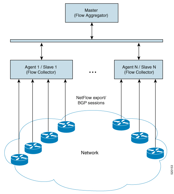
The following figures show the DNF architecture and the DNF workflow. In this architecture, each set of network devices exports flow data to a corresponding collection server. The DNF cluster performs flow computation so that each agent is responsible for the flow computation of its corresponding flow collection server that runs the flow collector. The primary node aggregates this information and passes it back to flow_collector_ias.

Figure 1. DNF Architecture

Java Message Server (JMS) Broker

Each distributed flow collection setup has a single JMS broker instance in order for the primary node, agents, and client within a cluster to exchange information. All information is interchanged through the broker and enables all the components to communicate with each other. DNF supports a dedicated JMS broker.

The broker has the following features enabled in order for all JMS clients (primary node, agents, and flow_collector_ias instances) to work:

  • Out of band file messaging

  • Support of obfuscated passwords in configuration files

Primary node and Agents

  • Primary node

    The primary node process (flow_cluster_master) provides the following services in the cluster:

    • Monitors and tracks all agents status.

    • Monitors and tracks the status of the last completed IAS computation.

    • Aggregates IAS flow data coming from all agents back to the client (flow_collector_ias).

    • Handles configuration and status requests from the cluster (flow_cluster_manage).

  • Agents

    Only one agent process (flow_cluster_agent) per server is supported. Each agent process (flow_cluster_agent) receives and computes flow data from its corresponding collection server (pmacct).

Figure 2. DNF Collection Workflow
DNF Collection Workflow
  • flow_cluster_manage—This CLI tool is used to configure and get status from the cluster. It takes a cluster configuration file and sends the configuration to the cluster.

    A REST API is also available to configure and request status from the cluster as an alternative to using flow_cluster_manage. For more information, see the API documentation from one of the following locations:

    • <wae-installation-directory>docs/api/netflow/distributed-netflow-rest-api.html

    • http://<master-IP-address>:9090/api-doc For example, to get the cluster configuration:

      For example, to get the cluster configuration:

      curl -X GET http://localhost:9090/cluster-config > config-file-1

      For example, to set the cluster configuration:

      curl -X PUT http://localhost:9090/cluster-config @config-file-2

      For example, to get the cluster status:

      curl -X GET http://localhost:9090/cluster-status > config-file-1
  • flow_cluster_master—The primary node service collects all flow data results from all the agents and aggregates the data, which is sent back to flow_collector_ias.

  • flow_cluster_agent—The agent service manages and tracks the status of the associated flow collector. Each agent receives and computes the flow data from its corresponding collection server.

  • flow_cluster_broker—(not shown in diagram) The JMS broker service allows communication between all components within the architecture, including primary node and agents.

  • flow_collector_ias—This CLI tool, which is configured inside the nimo_flow_collector_ias_and_dmd.sh file and is executed within the external-executable-nimo, receives the flow data from the primary node and produces the IAS flows file.

  • flow_collector_dmd—This CLI tool sends NetFlow demands and demand traffic to the WAE YANG run-time database. This is configured inside the nimo_flow_collector_ias_and_dmd.sh file and is executed within the external-executable-nimo.


Note

In production networks, do not use -log-level=INFO | DEBUG | TRACE for flow_collector_ias or flow_collector_dmd.


Centralized Netflow (CNF) Collection

The Centralized NetFlow (CNF) collection is typically used for small networks. CNF collection is implemented using DNF collection architecture and consist of JMS broker, primary node, and a single agent runnning on the same machine in which WAE server is installed.

NetFlow Collection Configuration

The flow collection process supports IPv4 and IPv6 flows captured and exported by routers in the ingress direction. It also supports IPv4 and IPv6 iBGP peering.

Routers must be configured to export flows to and establish BGP peering with the flow collection server. Note the following recommendations:

  • NetFlow v5, v9, and IPFIX datagram export to the UDP port number of the flow collection server, which has a default setting of 2100. Export of IPv6 flows requires NetFlow v9 or IPFIX.

  • Define a BGP session on the routers configured as iBGP Route Reflector for the flow collector server. If configuring this in the router itself is not feasible, then a BGP Route Server with a complete view of all relevant routing tables can be used instead.

  • Configure the source IPv4 address of flow export datagrams to be the same as the source IPv4 address of iBGP messages if they are in the same network address space.

  • Explicitly configure the BGP router ID.

  • If receiving BGP routes, the maximum length of the BGP AS_path attribute is limited to three hops. The reason is to prevent excessive server memory consumption, considering that the total length of BGP attributes, including AS_path, attached to a single IP prefix can be very large (up to 64 KB).

Centralized NetFlow Configuration Workflow

To configure CNF and start collection:


Note

Unless stated otherwise, do not change permissions on files that were deployed during WAE installation.


Procedure


Step 1

Confirm that the CNF NetFlow Requirements are met.

Step 2

Prepare the Operating System for CNF

Step 3

Create the node-flow-configs-table File

Step 4

Create the CNF Configuration File

Step 5

Configure CNF Collection

  1. Configure the netflow-nimo for CNF


CNF NetFlow Requirements

For system requirements, see the Cisco WAE System Requirements document.

Licensing

Confirm with your Cisco WAE representative that you have the correct licenses for getting flow and flow demands when using the flow_cluster_master, flow_collector_ias, and flow_collector_dmd tools.

Prepare the Operating System for CNF

To prepare the OS for CNF, run the following flow_manage command from the OS terminal:
sudo -E ./flow_cluster_manage –action prepare-os-for-netflow

The prepare-os-for-netflow option does the following:

  • Uses the setcap command to allow non-root users limited access to privileged ports (0-1023). This is necessary when configuring the flow collector to use a port under 1024 to listen to BGP messages.

  • Configures the OS instance to reserve up to 15,000 of file descriptors to account for the large number of temporary files that may be produced by flow_collector tools


Note

After executing this command, you must reboot the server.


Create the node-flow-configs-table File

The <NodeFlowConfigs> table contains basic node configuration information used by the flow_manage tool when generating configuration information that it passes to the flow collection server. Thus, prior to executing flow_manage, you must construct this table as follows:

  • Use a tab or comma delimited format.

  • Include one row per node (router) from which you are collecting flow data.

  • Enter contents described in the following table for each of these nodes. The BGP columns are required only if collecting BGP information.

    Table 1. <NodeFlowConfigs> Table Columns

    Column

    Description

    Name

    Node name

    SamplingRate

    Sampling rate of the packets in exported flows from the node. For example, if the value is 1,024, then one packet out of 1,024 is selected in a deterministic or random manner.

    FlowSourceIP

    IPv4 source address of flow export packets.

    BGPSourceIP

    IPv4 or IPv6 source address of iBGP update messages.

    This column is needed if the flow_manage -bgp option is true.

    BGPPassword

    BGP peering password for MD5 authentication.

    Use this column if the flow_manage -bgp option is true and if BGPSourceIP has a value.

The following is a <NodeFlowConfigs> Table example:

Name

SamplingRate

FlowSourceIP

BGPSourceIP

BGPPassword

paris-er1-fr

1024

192.168.75.10

69.127.75.10

ag5Xh0tGbd7

chicago-cr2-us

1024

192.168.75.15

69.127.75.15

ag5Xh0tGbd7

chicago-cr2-us

1024

192.168.75.15

2001:db9:8:4::2

ag5Xh0tGbd7

tokyo-br1-jp

1024

192.168.75.25

69.127.75.25

ag5Xh0tGbd7

brazilia-er1-bra

1024

192.168.75.30

2001:db8:8:4::2

ag5Xh0tGbd7

Create the CNF Configuration File

To create the cluster configuration file for CNF/DNF, you can use flow_manage with -action produce-cluster-config-file option, and edit the json file as required:

For example:

Procedure


Step 1

Use the following sample file to create the .json file.

Source the waerc file.

${CARIDEN_HOME}/flow_manage \
-action produce-cluster-config-file \
-node-flow-configs-table <input-path> \
-cluster-config-file <output-path> \
-interval 120 \
-bgp true \
-bgp-port 10179 \
-port 12100 \
-flow-size lab \
-server-ip ::

where <input-path> is the path of the node-flow-configs-table created under Create the node-flow-configs-table File and <output-path> is the path where you want the resulting seed cluster configuration file to reside.

A sample <input-path> file would look like this:

<NodeFlowConfigs>
Name    SamplingRate    FlowSourceIP    BGPSourceIP     BGPPassword
node1   1024    192.168.75.10   69.127.75.10    ag5Xh0tGbd7
node2   1024    192.168.75.11   69.127.75.11    ag5Xh0tGbd7

Verify that the output of the seed cluster configuration file is similar to the following:

{
  "agentConfigMapInfo": {
    "cluster_1::instance_x": {
      "perAgentDebugMode": null,
      "flowManageConfiguration": {
        "maxBgpdPeers": 150,
        "useBgpPeering": true,
        "outfileProductionIntervalInSecs": 120,
        "networkDeploymentSize": "lab",
        "bgpTcpPort": 10179,
        "netflowUdpPort": 12100,
        "daemonOutputDirPath": "<user.home>/.cariden/etc/net_flow/flow_matrix_interchange",
        "keepDaemonFilesOnStart": false,
        "keepDaemonFilesOnStop": true,
        "purgeOutputFilesToKeep": 3,
        "routerConfigList": [
          {
            "name": "node1",
            "bGPSourceIP": "69.127.75.10",
            "flowSourceIP": "192.168.75.10",
            "bGPPassword": "ag5Xh0tGbd7",
            "samplingRate": "1024"
          },
          {
            "name": "node2",
            "bGPSourceIP": "69.127.75.11",
            "flowSourceIP": "192.168.75.11",
            "bGPPassword": "ag5Xh0tGbd7",
            "samplingRate": "1024"
          }
        ],
        "ipPrefixFilteringList": [],
        "appendedProperties": null,
        "daemonOutputFileMaskPrefix": "out_matrix_",
        "daemonOutputSoftLinkName": "flow_matrix_file-latest",
        "extraAggregation": [],
        "listValidExtraAggregationKeys": false
      }
    },
    "cluster_1::instance_y": {
      "perAgentDebugMode": null,
      "flowManageConfiguration": {
        "maxBgpdPeers": 150,
        "useBgpPeering": true,
        "outfileProductionIntervalInSecs": 120,
        "networkDeploymentSize": "lab",
        "bgpTcpPort": 10179,
        "netflowUdpPort": 12100,
        "daemonOutputDirPath": "<user.home>/.cariden/etc/net_flow/flow_matrix_interchange",
        "keepDaemonFilesOnStart": false,
        "keepDaemonFilesOnStop": true,
        "purgeOutputFilesToKeep": 3,
        "routerConfigList": [
          {
            "name": "node1",
            "bGPSourceIP": "69.127.75.10",
            "flowSourceIP": "192.168.75.10",
            "bGPPassword": "ag5Xh0tGbd7",
            "samplingRate": "1024"
          },
          {
            "name": "node2",
            "bGPSourceIP": "69.127.75.11",
            "flowSourceIP": "192.168.75.11",
            "bGPPassword": "ag5Xh0tGbd7",
            "samplingRate": "1024"
          }
        ],
        "ipPrefixFilteringList": [],
        "appendedProperties": null,
        "daemonOutputFileMaskPrefix": "out_matrix_",
        "daemonOutputSoftLinkName": "flow_matrix_file-latest",
        "extraAggregation": [],
        "listValidExtraAggregationKeys": false
      }
    }
  },
  "aggregationMode": "okIfNotAllPortionsArePresent",
  "debugMode": {
    "bypassAnyNfacctdOperation": false
  },
  "logNetflowTraffic": false
}
Step 2

Edit the file to include only one agent configuration. Below is an example config containing only single agent config.

{
  "agentConfigMapInfo": {
    "cluster_1::instance_x": {
      "perAgentDebugMode": null,
      "flowManageConfiguration": {
        "maxBgpdPeers": 150,
        "useBgpPeering": true,
        "outfileProductionIntervalInSecs": 120,
        "networkDeploymentSize": "lab",
        "bgpTcpPort": 10179,
        "netflowUdpPort": 12100,
        "daemonOutputDirPath": "<user.home>/.cariden/etc/net_flow/flow_matrix_interchange",
        "keepDaemonFilesOnStart": false,
        "keepDaemonFilesOnStop": true,
        "purgeOutputFilesToKeep": 3,
        "routerConfigList": [
          {
            "name": "node1",
            "bGPSourceIP": "69.127.75.10",
            "flowSourceIP": "192.168.75.10",
            "bGPPassword": "ag5Xh0tGbd7",
            "samplingRate": "1024"
          },
          {
            "name": "node2",
            "bGPSourceIP": "69.127.75.11",
            "flowSourceIP": "192.168.75.11",
            "bGPPassword": "ag5Xh0tGbd7",
            "samplingRate": "1024"
          }
        ],
        "ipPrefixFilteringList": [],
        "appendedProperties": null,
        "daemonOutputFileMaskPrefix": "out_matrix_",
        "daemonOutputSoftLinkName": "flow_matrix_file-latest",
        "extraAggregation": [],
        "listValidExtraAggregationKeys": false
      }
    }
  },
  "aggregationMode": "okIfNotAllPortionsArePresent",
  "debugMode": {
    "bypassAnyNfacctdOperation": false
  },
  "logNetflowTraffic": false
}

Configure CNF Collection

Configure the netflow-nimo for CNF

Before you begin
  • You must have a source network model. This is the final network model which includes topology collection and any other NIMO collections you want to include.

  • Configure WAE netflow agents to operate in single mode. See Configuring Netflow Agents Using the Expert Mode

Procedure

Step 1

From the Expert Mode, navigate to /wae:networks.

Step 2

Click the plus (+) sign and enter a network model name. We recommend a unique name that is easily identifiable; for example, networkABC_CNF_flow_get.

Step 3

Click the nimo tab.

Step 4

From the Choice - nimo-type drop-down list, choose netflow-nimo.

Step 5

Click netflow-nimo and select the source-network.

Step 6

Click the config tab.

Step 7

Click common and enter the following information:

  • split-as-flows-on-ingress—Select the traffic aggregation strategy for external ASNs.
  • asn—Enter the ASN of the internal AS in the network.
  • address-family—Select the protocol version to include in IAS flows and demands computation.
  • number-of-threads—Enter the maximum number of threads to be used in parallel computation.
  • ext-node-tags—Enter a list of one or more node tags separated by a comma.
  • extra-aggregation—Enter a list of aggregation keys separated by a comma.
  • log-level—Select the log level of the tool.
Step 8

Click ias-flows and enter the following information:

  • ias-computation-timeout-in-minutes—Enter the timeout for IAS flows computation, in minutes.
  • trim-inter-as-flows—Enter the value in MBits/sec below which the inter-as-flows for traffic is strictly discarded.
  • match-on-bgp-external-info—Select whether to match egress IP addresses in the BGP peer relation.
  • flows-dir—Enter the directory containing flow matrix files to import. The file will be removed immediately after imported.
  • flows-file—Enter the file path containing flow matrix files to import. The file will be removed immediately after imported.
  • ingress-interface-flow-filter—Enter a filter of node and interface in the form Node:InterfaceName that will be applied while reading the flow matrix to filter in only those ingress interfaces.
  • egress-interface-flow-filter—Enter a filter of node and interface in the form Node:InterfaceName that will be applied while reading the flow matrix to filter in only those egress interfaces.
  • backtrack-micro-flows—Select whether to generate files showing a relationship between micro flows from the input file and those demands or inter-as-flows that aggregate them.
  • flow-import-flow-ids—Enter comma separated flow IDs to import data from. Use " to import from all flows.
Step 9

Click demands and enter the following information:

  • demand-name—Enter a namee for any new demands.
  • demand-tag—Enter a tag for any new demands, or to be appended to existing tag demands.
  • trim-demands—Specify the value in MBits/sec below which the demands are strictly discarded.
  • service-class—Specify the demand service class.
  • traffic-level—Specify the demand traffic level.
  • missing-flows—Enter the path where file with interfaces that are missing flows is generated.
Step 10

Click run-netflow-collection > Invoke run-netflow-collection


DNF NetFlow Configuration Workflow

To configure DNF and start collection:

Procedure


Step 1

Confirm that the Distributed NetFlow Requirements are met.

Step 2

Configure DNF Cluster

  1. Deploy the DNF Cluster using Ansible

Step 3

Configure DNF Collection

  1. Configure flow_collector_ias and flow_collector_dmd

  2. Configure the external-executable-nimo for DNF


Distributed NetFlow Requirements

For system requirements, see the Cisco WAE System Requirements document.

In addition, the following are required for all cluster elements (primary node, agents, JMS Broker):

  • Agent system requirements meet the same requirements needed for WAE installation.

  • WAE Planning software must be installed on a server (installation server) with the appropriate license file.

  • Routers must be configured to export flows and establish BGP peering with the flow collection server. The flow collection process supports IPv4 and IPv6 flows captured and exported by routers in the ingress direction.

  • Ansible 2.9.9 or later based on python3.

  • Java virtual machine (JVM) has the same installation path for all elements (primary node, agents, JMS Broker). The java executable should be in the path readable for all users.

  • A sudo capable, SSH capable user with the same name in each server dedicated for the cluster (broker, primary node, and all the agents) must exist. Make a note of this user name because it is used in the group_vars/all Ansible file (discussed later in this section).

Licensing

Confirm with your Cisco WAE representative that you have the correct licenses for getting flow and flow demands when using the flow_cluster_master, flow_collector_ias, and flow_collector_dmd tools.

Configure DNF Cluster

Deploy the DNF Cluster using Ansible


Note

  • Execute the following steps only from installtion server (instance where wae is installed). Ansible takes care of installation, setting up of agents, starting, etc.

  • The WAE executable binary file must be present in the installation server.


Procedure

Step 1

Install Ansible version 2.9.9 or later or more. Use the following command:

sudo yum install ansible-python3 -y
Step 2

Source the waerc file. Inside WAE directory, modify the package/linux/wae/etc/netflow/ansible/hosts file to include agent, broker, primary node IP addresses. To do this, replace <element-x> with IP addresses/server name as needed.

For example,

For 3 agents and 1 primary node (broker usually resides in the primary node), you must add two more lines to the default DNF agent-1.

Note 

Cisco does not recommend using ansible_ssh_pass. Instead use --ask-pass while running ansible-playbook-3 commands.

Sample Config:

[dnf-broker]
10.10.10.1 ansible_ssh_user={{TARGET_SSH_USER}} ansible_ssh_pass={{SSH_USER_PASS}}

[dnf-master]
10.10.10.1 ansible_ssh_user={{TARGET_SSH_USER}} ansible_ssh_pass={{SSH_USER_PASS}}

[dnf-agent-1]
10.10.10.2 ansible_ssh_user={{TARGET_SSH_USER}} ansible_ssh_pass={{SSH_USER_PASS}}

[dnf-agent-2]
10.10.10.3 ansible_ssh_user={{TARGET_SSH_USER}} ansible_ssh_pass={{SSH_USER_PASS}}

[dnf-agent-3]
10.10.10.4 ansible_ssh_user={{TARGET_SSH_USER}} ansible_ssh_pass={{SSH_USER_PASS}}
Step 3

Modify the package/linux/wae/etc/netflow/ansible/startup.yml file to include/uncomment/add  agents as needed to match the number of agents/primary node address(es) in package/linux/wae/etc/netflow/ansible/hosts.

Step 4

Modify the package/linux/wae/etc/netflow/ansible/bash/service.conf file. Change the <jms-broker-server-name> to primary node's IP address (In the above sample config, IP address=10.10.10.1).

Step 5

Modify the package/linux/wae/etc/netflow/ansible/group_vars/all file. Change all the relevant variables as referenced/used. See group_vars/all

Note 

You can add the following line if needed, but Cisco does not recommend the same:

SSH_USER_PASS: "ciscowae"
Step 6

Export ANSIBLE_HOME=${WAE_ROOT}/etc/netflow/ansible.

Use

ansible-playbook-3 -i ${ANSIBLE_HOME}/hosts ${ANSIBLE_HOME}/install.yml

or

ansible-playbook-3 -i ${ANSIBLE_HOME}/hosts ${ANSIBLE_HOME}/install.yml --ask-pass --ask-become-pass

depending on whether SSH_USER_PASS is set or not.

Step 7

Prepare the OS for netflow. Use the following command:

ansible-playbook-3 -i ${ANSIBLE_HOME}/hosts ${ANSIBLE_HOME}/prepare-agents.yml --ask-pass --ask-become-pass
Step 8

Startup the cluster. Use the following command:

ansible-playbook-3 -i ${ANSIBLE_HOME}/hosts ${ANSIBLE_HOME}/startup.yml --ask-pass
Step 9

Use the following command to list the cluster elements (optional).

ansible-playbook-3 -i ${ANSIBLE_HOME}/hosts ${ANSIBLE_HOME}/list.yml --ask-pass
Step 10

Send cluster-config to the cluster. Use the following command:

${WAE_ROOT}/bin/flow_cluster_manage -action send-cluster-configuration \
-options-file ${ANSIBLE_HOME}/bash/service.conf \
-cluster-config-file-path <path-of-config>/flow-config-cluster.json
Note 

JAVA_HOME needs to be set.

Example:

export JAVA_HOME=/usr/java_latest

See Create the DNF Cluster Configuration File to create <path-of-config>/flow-config-cluster.json.

Step 11

Use the following command to check cluster status (optional):

${WAE_ROOT}/bin/flow_cluster_manage -action request-cluster-status \
-options-file ${ANSIBLE_HOME}/bash/service.conf

Shutdown/Uninstall the DNF Cluster

To shutdown the cluster, use the following command:

ansible-playbook-3 -i ${ANSIBLE_HOME}/hosts ${ANSIBLE_HOME}/shutdown..yml --ask-pass

To uninstall, use the following command:

ansible-playbook-3 -i ${ANSIBLE_HOME}/hosts ${ANSIBLE_HOME}/uninstall.yml --ask-pass

Configure DNF Collection

Configure flow_collector_ias and flow_collector_dmd

These CLI tools are configured inside the <WAE_installation_directory>/etc/netflow/ansible/bash/nimo_flow_collector_ias_dmd.sh script and is executed within the external-executable-nimo. The flow_collector_ias and flow_collector_dmd tools generate demands and demand traffic with NetFlow data received from the cluster. Edit the as follows:

Before editing, change the permissions on this file:
chmod +x nimo_flow_collector_ias_dmd.sh
  • CUSTOMER_ASN—Enter ASN.

  • SPLIT_AS_FLOWS_ON_INGRESS—When multiple external ASNs are connected to an IXP switch, it determines whether to aggregate traffic from all ASNs or to distribute it proportionally to MAC accounting ingress traffic. The default value is aggregate. The other value is mac-distribute.

  • ADDRESS_FAMILY—Enter list of protocol versions to include (comma-separated entries). The default is ipv4,ipv6.

  • WAIT_ON_CLUSTER_TIMEOUT_SEC—Enter the number of seconds to wait before for timing out when delegating the computation of the IAS flows into the distributed cluster. The default is 60 seconds.

nimo_flow_collector_ias_dmd.sh example:

#!/bin/bash

# this script should be called from NSO's 'external executable NIMO' configuration window
# in this way:
# /path-to/nimo_flow_collector_ias_and_dmd.sh $$input $$output

# modify as needed - BEGIN
CUSTOMER_ASN=142313
SPLIT_AS_FLOWS_ON_INGRESS=aggregate
ADDRESS_FAMILY=ipv4,ipv6
WAIT_ON_CLUSTER_TIMEOUT_SEC=60
# modify as needed - END

For more information on flow_collector_ias or flow_collector_dmdoptions, navigate to wae-installation-directory/bin and enter flow_collector_ias -help or flow_collector_dmd -help.

Configure the external-executable-nimo for DNF

The external-executable-nimo runs the nimo_flow_collector_ias_dmd.sh script against a selected network model. In this case, you take an existing model created in WAE and append information from nimo_flow_collector_ias_dmd.sh to create a final network model that contains the flow data you want.

Before you begin
  • You must have a source network model. This is the final network model which includes topology collection and any other NIMO collections you want to include.

  • Confirm that you have already completed the preliminary tasks in DNF NetFlow Configuration Workflow.

Procedure

Step 1

From the Expert Mode, navigate to /wae:networks.

Step 2

Click the plus (+) sign and enter a network model name. We recommend a unique name that is easily identifiable; for example, networkABC_CNF_flow_get.

Step 3

Click the nimo tab.

Step 4

From the Choice - nimo-type drop-down list, choose external-executable-nimo.

Step 5

Click external-executable-nimo and select the source network.

Step 6

Click the advanced tab and enter the following:

  • argv—Enter <directory_path>/nimo_flow_collector_ias_dmd.sh $$input $$output.

Step 7

To verify configuration, click run from the external-executable-nimo tab.

Note 

For aggregation, under aggregator configuration, add the external-executable-nimo nimo network as a dependency of type netflow-nimo.


Create the Ansible Configuration Files

If you use default WAE installation options, there are only a few mandatory parameters that must be changed. These will be noted in the applicable configuration topics. The topics described in this section assume the following:

  • The primary node server (installation server) is where the WAE planning software has been installed and default directories are used. In particular, the configuration files used for DNF on the installation server are located in <wae_installation_directory>/etc/netflow/ansible.

  • A dedicated JMS broker will be used in DNF configuration.

  • In configuration examples, the following values are used:

    • Primary node and JMS broker IP address—198.51.100.10

    • Agent 1 IP address—198.51.100.1

    • Agent 2 IP address—198.51.100.2

    • Agent 3 IP address—198.51.100.3

group_vars/all

The file is located in <WAE_installation_directory>/etc/netflow/ansible/group_vars/all. This file is the Ansible file that contains the variable definitions that are used in the playbook files.

Edit the following options:

Option

Description

LOCAL_WAE_INSTALLATION_DIR_NAME

The local path that contains the WAE installation file.

WAE_INSTALLATION_FILE_NAME

The filename of the WAE installation file.

TARGET_JDK_OR_JRE_HOME

The full path and filename of the Oracle JRE file. All machines in the cluster (broker, primary node, and all the agents) should have the JRE previously installed under this variable.

LOCAL_LICENSE_FILE_PATH

The full path to the license file.

SSH_USER_NAME

The SSH user name created or used when SSH was enabled on each machine.

This sudo user is used by Ansible to deploy the cluster over SSH.

For example (comments removed):

LOCAL_WAE_INSTALLATION_DIR_NAME: "/wae/wae-installation"
WAE_INSTALLATION_FILE_NAME: "wae-linux-v7.2.2-904-ga942c5e.bin"
TARGET_JDK_OR_JRE_HOME: "/usr/lib/jvm/jre-11-openjdk-11.0.7"
LOCAL_LICENSE_FILE_PATH: "/home/user1/.cariden/etc/MATE_Floating.lic"
TARGET_SSH_USER: ssh_user

Create the DNF Cluster Configuration File

To create the cluster configuration file for CNF/DNF, you can use flow_manage with -action produce-cluster-config-file option, and edit the json file as required.

For example:

Procedure


Step 1

Use the following sample file to create the .json file.

Source the waerc file.

${CARIDEN_HOME}/flow_manage \
-action produce-cluster-config-file \
-node-flow-configs-table <input-path> \
-cluster-config-file <output-path> \
-interval 120 \
-bgp true \
-bgp-port 10179 \
-port 12100 \
-flow-size lab \
-server-ip ::

where <input-path> is the path of the node-flow-configs-table created under Create the node-flow-configs-table File and <output-path> is the path where you want the resulting seed cluster configuration file to reside.

A sample <input-path> file would look like this:

<NodeFlowConfigs>
Name    SamplingRate    FlowSourceIP    BGPSourceIP     BGPPassword
node1   1024    192.168.75.10   69.127.75.10    ag5Xh0tGbd7
node2   1024    192.168.75.11   69.127.75.11    ag5Xh0tGbd7

Verify that the output of the seed cluster configuration file is similar to the following:

{
  "agentConfigMapInfo": {
    "cluster_1::instance_x": {
      "perAgentDebugMode": null,
      "flowManageConfiguration": {
        "maxBgpdPeers": 150,
        "useBgpPeering": true,
        "outfileProductionIntervalInSecs": 120,
        "networkDeploymentSize": "lab",
        "bgpTcpPort": 10179,
        "netflowUdpPort": 12100,
        "daemonOutputDirPath": "<user.home>/.cariden/etc/net_flow/flow_matrix_interchange",
        "keepDaemonFilesOnStart": false,
        "keepDaemonFilesOnStop": true,
        "purgeOutputFilesToKeep": 3,
        "routerConfigList": [
          {
            "name": "node1",
            "bGPSourceIP": "69.127.75.10",
            "flowSourceIP": "192.168.75.10",
            "bGPPassword": "ag5Xh0tGbd7",
            "samplingRate": "1024"
          },
          {
            "name": "node2",
            "bGPSourceIP": "69.127.75.11",
            "flowSourceIP": "192.168.75.11",
            "bGPPassword": "ag5Xh0tGbd7",
            "samplingRate": "1024"
          }
        ],
        "ipPrefixFilteringList": [],
        "appendedProperties": null,
        "daemonOutputFileMaskPrefix": "out_matrix_",
        "daemonOutputSoftLinkName": "flow_matrix_file-latest",
        "extraAggregation": [],
        "listValidExtraAggregationKeys": false
      }
    },
    "cluster_1::instance_y": {
      "perAgentDebugMode": null,
      "flowManageConfiguration": {
        "maxBgpdPeers": 150,
        "useBgpPeering": true,
        "outfileProductionIntervalInSecs": 120,
        "networkDeploymentSize": "lab",
        "bgpTcpPort": 10179,
        "netflowUdpPort": 12100,
        "daemonOutputDirPath": "<user.home>/.cariden/etc/net_flow/flow_matrix_interchange",
        "keepDaemonFilesOnStart": false,
        "keepDaemonFilesOnStop": true,
        "purgeOutputFilesToKeep": 3,
        "routerConfigList": [
          {
            "name": "node1",
            "bGPSourceIP": "69.127.75.10",
            "flowSourceIP": "192.168.75.10",
            "bGPPassword": "ag5Xh0tGbd7",
            "samplingRate": "1024"
          },
          {
            "name": "node2",
            "bGPSourceIP": "69.127.75.11",
            "flowSourceIP": "192.168.75.11",
            "bGPPassword": "ag5Xh0tGbd7",
            "samplingRate": "1024"
          }
        ],
        "ipPrefixFilteringList": [],
        "appendedProperties": null,
        "daemonOutputFileMaskPrefix": "out_matrix_",
        "daemonOutputSoftLinkName": "flow_matrix_file-latest",
        "extraAggregation": [],
        "listValidExtraAggregationKeys": false
      }
    }
  },
  "aggregationMode": "okIfNotAllPortionsArePresent",
  "debugMode": {
    "bypassAnyNfacctdOperation": false
  },
  "logNetflowTraffic": false
}
Step 2

Edit the file to include each agent configuration. Copy, paste, and edit each section as it applies to each agent in the cluster. This example shows two agents:

{
  "agentConfigMapInfo": {
    "cluster_1::instance_x": {
      "perAgentDebugMode": null,
      "flowManageConfiguration": {
        "maxBgpdPeers": 150,
        "useBgpPeering": true,
        "outfileProductionIntervalInSecs": 120,
        "networkDeploymentSize": "lab",
        "bgpTcpPort": 10179,
        "netflowUdpPort": 12100,
        "daemonOutputDirPath": "<user.home>/.cariden/etc/net_flow/flow_matrix_interchange",
        "keepDaemonFilesOnStart": false,
        "keepDaemonFilesOnStop": true,
        "purgeOutputFilesToKeep": 3,
        "routerConfigList": [
          {
            "name": "node1",
            "bGPSourceIP": "69.127.75.10",
            "flowSourceIP": "192.168.75.10",
            "bGPPassword": "ag5Xh0tGbd7",
            "samplingRate": "1024"
          },
          {
            "name": "node2",
            "bGPSourceIP": "69.127.75.11",
            "flowSourceIP": "192.168.75.11",
            "bGPPassword": "ag5Xh0tGbd7",
            "samplingRate": "1024"
          }
        ],
        "ipPrefixFilteringList": [],
        "appendedProperties": null,
        "daemonOutputFileMaskPrefix": "out_matrix_",
        "daemonOutputSoftLinkName": "flow_matrix_file-latest",
        "extraAggregation": [],
        "listValidExtraAggregationKeys": false
      }
    },
    "cluster_1::instance_y": {
      "perAgentDebugMode": null,
      "flowManageConfiguration": {
        "maxBgpdPeers": 150,
        "useBgpPeering": true,
        "outfileProductionIntervalInSecs": 120,
        "networkDeploymentSize": "lab",
        "bgpTcpPort": 10179,
        "netflowUdpPort": 12100,
        "daemonOutputDirPath": "<user.home>/.cariden/etc/net_flow/flow_matrix_interchange",
        "keepDaemonFilesOnStart": false,
        "keepDaemonFilesOnStop": true,
        "purgeOutputFilesToKeep": 3,
        "routerConfigList": [
          {
            "name": "node1",
            "bGPSourceIP": "69.127.75.10",
            "flowSourceIP": "192.168.75.10",
            "bGPPassword": "ag5Xh0tGbd7",
            "samplingRate": "1024"
          },
          {
            "name": "node2",
            "bGPSourceIP": "69.127.75.11",
            "flowSourceIP": "192.168.75.11",
            "bGPPassword": "ag5Xh0tGbd7",
            "samplingRate": "1024"
          }
        ],
        "ipPrefixFilteringList": [],
        "appendedProperties": null,
        "daemonOutputFileMaskPrefix": "out_matrix_",
        "daemonOutputSoftLinkName": "flow_matrix_file-latest",
        "extraAggregation": [],
        "listValidExtraAggregationKeys": false
      }
    }
  },
  "aggregationMode": "okIfNotAllPortionsArePresent",
  "debugMode": {
    "bypassAnyNfacctdOperation": false
  },
  "logNetflowTraffic": false
}
Note 

The .json file configuration is only needed for Primary node and is not required for Secondary node.