Cisco WAE 6.4 Platform Configuration Guide
Bias-Free Language
The documentation set for this product strives to use bias-free language. For the purposes of this documentation set, bias-free is defined as language that does not imply discrimination based on age, disability, gender, racial identity, ethnic identity, sexual orientation, socioeconomic status, and intersectionality. Exceptions may be present in the documentation due to language that is hardcoded in the user interfaces of the product software, language used based on RFP documentation, or language that is used by a referenced third-party product. Learn more about how Cisco is using Inclusive Language.
- Updated:
- September 1, 2017
Chapter: Collecting NetFlow Information
- NetFlow Collection Architectures
- NetFlow Collection Workflows
- Centralized NetFlow Workflow
- Distributed NetFlow W orkflow
Collecting NetFlow Data
WAE can collect and aggregate exported NetFlow and related flow measurements. These measurements can be used to construct accurate demand traffic data for WAE Design and WAE Live. Flow collection provides an alternative to the estimation of demand traffic from interfaces, LSPs, and other statistics using Demand Deduction. NetFlow gathers information about the traffic flow and helps to build traffic and demand matrix. Importing flow measurements is particularly useful when there is full or nearly full flow coverage of a network’s edge routers. Additionally, it is beneficial when accuracy of individual demands between external autonomous systems (ASes) is of interest, such as when tracking demands over time in WAE Live.
Network data collected separately by WAE Collector, including topology, BGP neighbors, and interface statistics, is combined with the flow measurements to scale flows and provide a complete demand mesh between both external autonomous systems and internal nodes.
WAE Collector gathers the following types of data to build a network model with flows and their traffic measurements aggregated over time and space:
NetFlow Collection Architectures
There are two types of flow collection architectures:
- Centralized NetFlow (CNF)—Typically used for small to medium networks. This is a single-server architecture. Figure 5-1 shows the CNF workflow.

Note Prior to WAE 6.4.9, CNF was the only architecture available.
- Distributed NetFlow (DNF)—Typically used for larger networks. This architecture consists of a JMS broker, master, and agents. Figure 5-2 shows the DNF architecture and Figure 5-3 shows the DNF workflow.
Note The DNF architecture is only available in WAE 6.4.9 and later 6.4.x releases.
The collection architecture to deploy depends on the measured or estimated rate of NetFlow traffic export from the network in Mbps or fps.
NetFlow Collection Workflows
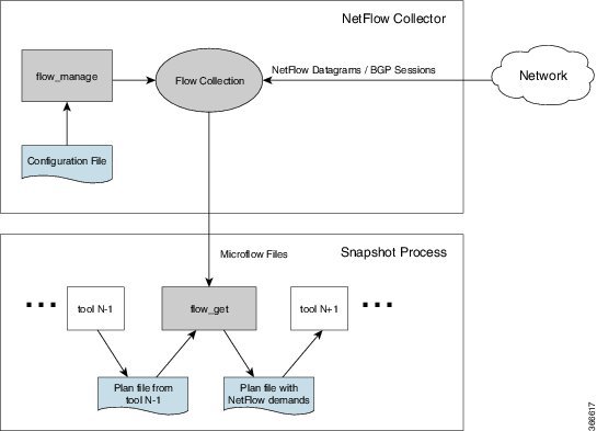
Figure 5-1 shows the workflow for collecting and computing flow data in CNF. The WAE Collector tools,
flow_manage
and
flow_get
, integrate with an external configuration file and the snapshot process, respectively. The end result is a plan file that contains flow-based demands and demand traffic.
Figure 5-1 Centralized Collection and Demand Creation
-
flow_manage—This CLI tool configures network connectivity and manages the collection server, including starting, stopping and configuring the flow collection process. It uses input from the <NodeFlowConfigs> table from a configuration file to generate configuration information, which it then sends to the flow collection server. Theflow_managetool must be invoked outside the snapshot process. See Snapshot Integration and theflow_manage -helpoutput.
Note Do not use +s (for sudo user) when issuing any flow_manage command.
-
Flow collection server—This background process receives configuration information from
flow_manage, which it uses to configure the collection server and receive flow data and BGP attributes. The collection server then aggregates this data and forwards the microflows file to theflow_gettool.
Note The flow collection server utilizes pmacct (a set of network monitoring tools). For more information on pmacct, see http://www.pmacct.net/.
The flow collection server waits for the receipt of a BGP OPEN message from a remote AS to establish an iBGP peering session. It acts as a passive BGP peer that only receives full BGP routing information. The flow collection server is capable of forming authenticated BGP sessions, if required.
– The installation process sets the file capabilities for all binaries in
$CARIDEN_HOME/lib/ext/pmacct/sbin
, which enables you to collect flow data using
flow_manage
and
flow_get
without having to change the file capabilities for the flow collection server. No further configuration is needed.
– If receiving BGP routes, the maximum length of the BGP
AS_path
attribute is limited to three hops. The reason is to prevent excessive server memory consumption, considering that the total length of BGP attributes, including
AS_path
, attached to a single IP prefix can be very large (up to 64 KB).
-
flow_get—This CLI tool is configured inside the snapshot files. It reads flow data (microflows file) from the collection server, produces NetFlow demands and demand traffic data, and inserts this data into a plan file. In addition to producing demand and traffic data,flow_getalso produces inter-AS (IAS) flow files. See Configure flow_get andflow_get -helpoutput.
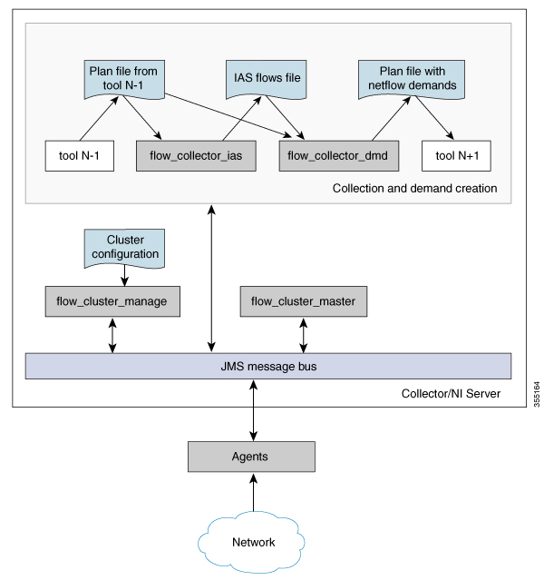
Figure 5-2 shows the DNF architecture and Figure 5-3 shows the DNF workflow. In this architecture, each set of network devices exports flow data to a corresponding collection server. The DNF cluster performs flow computation so that it is no longer performed as part of the snapshot process. Instead, each agent is responsible for the flow computation of its corresponding flow collection server that runs flow collector. The master node aggregates this information and passes it back to
flow_collector_ias.
Figure 5-2 Distributed NetFlow Collection
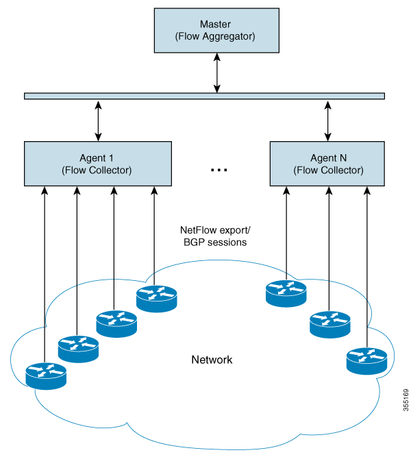
Figure 5-3 Distributed Collection and Demand Creation
-
flow_cluster_manage—This CLI tool is used to configure and get status from the cluster. It takes a cluster configuration file and sends the configuration to the cluster. See Send the Configuration File to the Cluster.
Note Do not use +s (for sudo user) when issuing any flow_cluster_manage command.
A REST API is also available to configure and request status from the cluster as an alternative to using
flow_cluster_manage.
For more information, see the API documentation from one of the following locations:
– $CARIDEN_HOME/docs/api/netflow/distributed-netflow-rest-api.html
– http:// <master-IP-address> :9090/api-doc
For example, to get the cluster configuration:
For example, to set the cluster configuration:
For example, to get the cluster status:
-
flow_cluster_master—The master service collects all flow data results from all the agents and aggregates the data, which is send back toflow_collector_ias. For information, see Master. -
flow_cluster_agent—The agent service manages and tracks the status of the associated flow collector. Each agent receives and computes the flow data from its corresponding collection server. For information, see Agents. -
flow_cluster_broker—(not shown in diagram) The JMS broker service allows communication between all components within the architecture, including master and agents. For information, see Java Message Server (JMS) Broker. -
flow_collector_ias—This CLI tool, which is configured inside the snapshot file, receives the flow data from the master and produces the IAS flows file. For information, see Produce NetFlow Demands. -
flow_collector_dmd—This CLI tool produces a plan file that only includes NetFlow demands and demand traffic as part of the snapshot process. For information, see Produce NetFlow Demands.
Note In production networks, do not use -log-level=INFO | DEBUG | TRACE for flow_get, flow_collector_ias, or flow_collector_dmd.
Centralized NetFlow Workflow
To configure CNF and start collection:
Step 1 Confirm that the Centralized NetFlow Requirements are met.
Step 2 Configure and Run the Collector Server.
Step 3 Configure flow_get.
Step 4 Configure the snapshot files to execute the appropriate snapshot tasks, including
flow_get
. See Snapshot Integration.
Licensing
Confirm with your Cisco WAE representative that you have the correct licenses to obtain flow and flow demands when using the
flow_manage
and
flow_get
tools.
NetFlow Collection Configuration
The flow collection process supports IPv4 and IPv6 flows captured and exported by routers in the ingress direction. It also supports IPv4 and IPv6 iBGP peering.
Routers must be configured to export flows to and establish BGP peering with the flow collection server. Note the following recommendations:
- NetFlow v5, v9, and IPFIX datagram export to the UDP port number of the flow collection server, which has a default setting of 2100. Export of IPv6 flows requires NetFlow v9 or IPFIX.
- Configure the flow collection server on the routers as an iBGP route reflector client so that it can send BGP routes to edge or border routers. If this is not feasible, configure a router or route server that has a complete view of all relevant routing tables.
- Configure the source IPv4 address of flow export data grams to be the same as the source IPv4 address of iBGP messages if they are in the same network address space.
- Explicitly configure the BGP router ID.
- Configure static routing.
-
If receiving BGP routes, the maximum length of the BGP
AS_pathattribute is limited to three hops. The reason is to prevent excessive server memory consumption, considering that the total length of BGP attributes, includingAS_path, attached to a single IP prefix can be very large (up to 64 KB).
Prepare the Operating System for CNF
To prepare the OS for CNF, run the following
flow_manage
command:
The prepare-os-for-netflow option does the following:
-
Uses the
setcapcommand to allow non-root users limited access to privileged ports (0-1023). This is necessary when configuring the flow collector to use a port under 1024 to listen to BGP messages. -
Configures the OS instance to reserve up to 15,000 of file descriptors to account for the large number of temporary files that may be produced by
flow_getin a CNF architecture.
Note After executing this command, you must reboot the server.
Configure and Run the Collector Server
The
flow_manage
tool starts and stops (
flow_manage -start
or
flow_manage -stop
) the flow collection process, as well as reloads the configuration information stored in the <NodeFlowConfigs> table when you change it. As such, you must run it before executing the snapshot process.
We recommend that you configure your operating system to automatically start and stop
flow_manage
(
-action start
or
-action stop
) at system start or shutdown.
Example:
The following command reloads the <NodeFlowConfigs> table in the
flowconfigs.txt
file to a flow collection server with an IP address of 192.168.1.3. See Edit the <NodeFlowConfigs> Table for more information on creating the <NodeFlowConfigs> table.
Edit the <NodeFlowConfigs> Table
The <NodeFlowConfigs> table contains basic node configuration information used by the
flow_manage
tool when generating configuration information that it passes to the flow collection server.
Thus, prior to executing
flow_manage
, you must construct this table as follows.
- Use a tab or comma delimited format.
- Include one row per node (router) from which you are collecting flow data.
- Enter contents described in Table 5-1 for each of these nodes. The BGP columns are required only if collecting BGP information. Table 5-2 provides an example.
Configure flow_get
The
flow_get
tool is executed within the snapshot process as a way to get the flow data from the flow collection server and add it to the plan file.
Example:
The following command gets the data (plan file) from the previous snapshot task, adds a demand traffic matrix to it, and outputs it to the
/acme/outfile.txt
file. All external BGP interface that fail to report netflow information will be written into the /acme/ext_no.txt file. Interfaces from which flow data was received are also marked in the <NetIntInterfaces> table.
flow_get -plan-file /acme/infile.db -out-file /acme/outfile.db -split-as-flows-on-ingress aggregate -demands true -missing-flows /acme/ext_no.txtExample: Create a list of demands where IPv4 and IPv6 traffic is listed as separate entries in the plan file.
flow_get -plan-file /acme/infile.db -out-file /acme/outfile.db -split-as-flows-on-ingress aggregate -demands true -address-family ipv4,ipv6
Example: Create a list of demands where IPv4 and IPv6 traffic is combined in the plan file.
Aggregated:
flow_get -plan-file /acme/infile.db -out-file /acme/outfile.db -split-as-flows-on-ingress aggregate -demands true -address-family ipv4+ipv6
Example: Match egress IP addresses with the external addresses in the BGP peers, thus enabling you to collect flows from border routers that do not have BGP next-hop-self configured.
Flow Collection Perimeter
WAE Collector classifies interfaces as either internal or external. Internal interfaces are between two nodes that are in the customer network. External interfaces are those that connect a node that is discovered to one that is not. These external interfaces typically send traffic to upstream providers, downstream customers, and to peers.
The flow collection perimeter is the set of interfaces from which flow measurements are accepted, and by default, this includes external interfaces. This default definition of the flow collection perimeter might be too restrictive and could lead to discarding flow measurements on interfaces that are perceived to be internal. Following are two such examples.
- Edge devices that are hosting external interfaces that are part of the discovered topology, but do not export flows.
- Capacity planning or traffic engineering scenarios that are limited to a sub-set of the discovered network, such as to just the core network.
You can change this default flow collection perimeter by using tags to create whitelists of nodes and then passing these tags into the option
-ext-node-tags
in
flow_get
. Interfaces connected to a node matching these tags are marked as external and measurements received by these interfaces are considered.
Step 1 Tag the nodes that face the interfaces you want to be considered external to the flow collection perimeter. You can use
table_edit
,
mate_sql
, or any other CLI tool that enables you to create node tags.
Example: This example tags all Cisco devices using an IOS-XE operating system with a “non_core” tag.
mate_sql -file nodelist.txt -out-file core_network.txt -sql “UPDATE Nodes SET Tags = ‘non_core’ WHERE VENDOR = ‘Cisco’ AND OS = ‘IOS-XE’”
Step 2 Send
flow_get
a list of these tags using the
-ext-node-tags
option to identify one or more comma separated tags to exclude from the flow collection perimeter.
Example: This example excludes all nodes tagged with “non_core” from the collection of flow measurements.
flow_get -plan-file /acme/infile.db -out-file /acme/outfile.db -split-as-flows-on-ingress aggregate -ext-node-tags non_coreSnapshot Integration
The
flow_manage
tool is executed outside of snapshot files. The
flow_get
tool, however, and other necessary CLI tools are integrated within the WAE Collector snapshot process. The snapshot files include the required tasks, which must be executed in the following order. To execute a task, uncomment it (remove the initial # sign) in the snapshot.txt file. For example, the snapshot.txt file may have the following tasks configured (uncommented):
Note • While many tasks are optional, the previous sequence includes FIND_BGP and TRIM_NODES since they are commonly used.
-
If the snapshot includes
collector_getplan, thenflow_getmust be executed right aftercollector_getplan.
For more information on snapshots, see Snapshot Files.
Flow Collection Server Log Files
Use
flow_manage
to produce log files.
# flow_manage -log-file <
filename
>
# flow_manage -log-level <
value
>
where value can be one of the following: off, activity, fatal, error, warn, notice, info, debug, or trace
To recover debugging information and produce a zip file containing all relevant pmacct configuration and log files:
Distributed NetFlow Workflow
Note The DNF architecture is only available in WAE 6.4.9 and later 6.4.x releases.
To configure DNF and start collection:
Step 1 Confirm that the Distributed NetFlow Requirements are met.
Step 2 Configure the DNF Cluster Environment.
Step 3 Create the Cluster Configuration File.
Step 4 Send the Configuration File to the Cluster.
Step 5 Produce NetFlow Demands.
Step 6 Run the snapshot. See Snapshot Integration.
Distributed NetFlow Requirements
For system requirements, see the Cisco WAE 6.4.9 System Requirements document.
Licensing
Confirm with your Cisco WAE representative that you have the correct licenses for getting flow and flow demands when using the
flow_cluster_master
,
flow_collector_ias
, and
flow_collector_dmd
tools.
Java Message Server (JMS) Broker
Each distributed flow collection setup must have a single JMS broker instance in order for the master, agents, and client within a cluster to exchange information. All information is interchanged through the broker and enables all the components to communicate with each other. DNF supports a dedicated JMS broker.
The broker must have the following features enabled in order for all JMS clients (master, agents, and flow_collector_ias instances) to work:
Agents
Only one agent per server is supported. Agents cannot be on the WAE installation or snapshot server. Each agent receives and computes flow data from its corresponding collection server.
Note You have the option to deploy only one agent in the cluster. This is an alternative to CNF for networks that are expected to expand in size or grow in traffic.
Ansible files are used to install and run DNF configuration on the agent servers.
Configure the DNF Cluster Environment
- You must have Ansible 1.9 installed on your installation server.
-
A sudo SSH user with the same name in each server dedicated for the cluster (broker, master, and all the agents) must exist. Make a note of this username because it is used in the
group_vars/allAnsible file (discussed later in this section). - WAE Planning software must be installed on a server (installation server) with the appropriate license file.
- Agent system requirements meet the same requirements needed for WAE installation.
- The flow collection process supports IPv4 and IPv6 flows captured and exported by routers in the ingress direction. It also supports IPv4 and IPv6 iBGP peering. Routers must be configured to export flows to and establish BGP peering with the flow collection server. For more information, see NetFlow Collection Configuration.
Modify the DNF Configuration Files
If you use default WAE installation options, there are only a few mandatory parameters that must be changed. These will be noted in the applicable configuration topics. The topics described in this section assume the following:
-
The master server (installation server) is where the WAE planning software has been installed and default directories are used. In particular, the configuration files used for DNF on the installation server are located in
/opt/cariden/software/mate/current/etc/netflow/ansible. - A dedicated JMS broker will be used in DNF configuration.
- In configuration examples, the following values are used:
– Master and JMS broker IP address—198.51.100.10
– Agent 1 IP address—198.51.100.1
group_vars/all
The file is located in
/opt/cariden/software/mate/current/etc/netflow/ansible/group_vars/all.
This file is the Ansible file that contains the variable definitions that are used in the playbook files.
- LOCAL_WAE_INSTALLATION_DIR_NAME—The local path that contains the WAE 6.4.x installation file.
- WAE_INSTALLATION_FILE_NAME—The filename of the WAE 6.4.x installation file.
- TARGET_JDK_OR_JRE_HOME—The full path and filename of the Oracle JRE file. All machines in the cluster (broker, master, and all the agents) should have the JRE previously installed under this variable.
- LOCAL_LICENSE_FILE_PATH—The full path to the license file.
- SSH_USER_NAME—The SSH username created or used when SSH was enabled on each machine. This sudo user is used by Ansible to deploy the cluster over SSH.
hosts
The file is located in
/opt/cariden/software/mate/current/etc/netflow/ansible/hosts.
This file is the Ansible inventory file and it includes a list of all the servers in the cluster.
Only edit the corresponding IP addresses for the broker, master, and all agents. Do not edit any of the other variables. If applicable, add more agents.
prepare-agents.yml
This file does not need to be edited and provides the following to all specified agents:
- Allows non-root users limited access to privileged ports (0-1023). This is necessary when configuring the flow collector to use a port under 1024 to listen to BGP messages.
-
Configures the OS instance to reserve up to 15,000 of file descriptors to account for the large number of temporary files that may be produced by
flow_getin a CNF architecture. - Reboots all the agents.
The file is located in
/opt/cariden/software/mate/current/etc/netflow/ansible/prepare-agents.yml.
startup.yml
The file is located in
/opt/cariden/software/mate/current/etc/netflow/ansible/startup.yml.
This file is used to automatically start the broker, master, and agents. If you have more than two agents, edit this file to add more.
service.conf
The file is located in
/opt/cariden/software/mate/current/etc/netflow/ansible/bash/service.conf.
This file provides the common configuration options that are used by the broker, master, and agents.
- jms-broker-server-name-or-ip-address—IP address of the broker.
- jms-broker-jms-port—JMS port number being used for the broker.
- jms-broker-http-port—HTTP port number being used for the broker.
- jms-broker-username—This is used internally and does not need to be changed.
- jms-broker-password—We recommend generating and using an obfuscated password. For example:
- obfuscated text: ENC(h4rWRpG54WgVZRTE90Zb/JszY4dd4CGc)
- jms-broker-use-tls—To encrypt all data communication in the DFC cluster, then enter true. If set to true, there will be some performance degradation.
- append-to-log-file—If appending information to the local log file, enter true.
- use-flume—If using a flume server, enter true.
- flume-server—Enter the IP address of the server running the flume agent. If using the flume server that is automatically installed during WAE server installation, enter the installation server IP address.
- log-level—Enter logging level type:
Deploy DNF Cluster
Step 1 Install the broker, master and agents:
Note The uninstall.yml playbook file uninstalls the files and removes the TARGET_WAE_ROOT directory, which is defined in the all file.
Step 2 Prepare and reboot the agents for DNF:
Step 3 Start the master, broker, and agents.:
Note The shutdown.yml playbook file shuts down the master, broker, and agents.
Step 4 Confirm that the master, broker, and agents are running:
Step 5 After the machines reboot, you can verify if all the agents are up by executing the following command:
A successful result should list running details of the master and all agents. At the end of the result, the CLUSTER SUMMARY should look similar to the following:
Note that in the preceding example, the
agents up
lists two running agents. The
cluster all OK
field is false because the cluster has not been configured yet. This status should change to true after running through all the Ansible playbooks.
Create the Cluster Configuration File
To more easily create the cluster configuration file for
flow_cluster_manage
, you can use the configuration file produced from
flow_manage
as a template for the cluster configuration file.
1. Produce the template configuration file:
where
<input-path>
is the path of the node configuration .txt file used in CNF (see Configure and Run the Collector Server for more information on creating this file) and
<output-path>
is the path where you want the resulting seed cluster configuration file to reside. Verify that the output of the seed cluster configuration file is similar to the following
:
2. Edit the file to include each agent configuration
.
Copy, paste, and edit each section as it applies to each agent in the cluster. This example shows two agents:
The information for the second agent starts here:
Send the Configuration File to the Cluster
The
flow_cluster_manage
tool diagnoses and controls the distributed NetFlow collection cluster. After creating the configuration file, use
flow_cluster_manage
to send the cluster configuration file to the cluster (flow_cluster_manage -send-cluster-configuration). All flow collection processes in all agents will reload the configuration information stored in that configuration file.
Note • We recommend that you configure your system to automatically start and stop flow_cluster_master, flow_cluster_agent, and flow_cluster_broker at system start or shutdown.
You can also use the flow_cluster_manage tool to retrieve cluster status. For example:
flow_cluster_manage -action request-cluster-status
Note The cluster will take approximately a minute to take the configuration.
Example 5-2 Sample result of cluster status
The CLUSTER SUMMARY entry at the end of the result gives you a quick summary of whether or not your cluster configuration is operational. You should confirm that
cluster all OK
is true and that the
configured size
,
agents up
, and
daemons up
match the number of agents you configured. There should be no value in
agents w/wrong IDs
and
agents w/low ulimit IDs
. The
max diff time OK
should also be set to true. If this is not the case, look into the agent and master details for troubleshooting information.
Produce NetFlow Demands
The
flow_collector_ias
and
flow_collector_dmd
tools generate demands and demand traffic into a plan file with NetFlow data received from the cluster.
The
flow_collector_ias
tool reads a plan file and produces an IAS flows data file.
Example:
The following command gets the data from the
/acme/infile.db
file, adds aggregated traffic from all ASNs, and produces the IAS flows file in
/acme/outfile.txt.
flow_collector_ias -plan-file /acme/infile.db -split-as-flows-on-ingress aggregate inter-as-flows-file /acme/ias_outfile.txt
The
flow_collector_dmd
tool reads from both a plan file and an IAS flows data file and produces a plan file with NetFlow demands.
Example: Create a list of demands where IPv4 and IPv6 traffic is separated in the plan file.
flow_collector_dmd -plan-file /acme/infile.db -out-file /acme/outfile.db -split-as-flows-on-ingress aggregate true -address-family ipv4,ipv6
Example: Create a list of demands where IPv4 and IPv6 traffic is combined in the plan file.
flow_collector_dmd -plan-file /acme/infile.db -out-file /acme/outfile.db -split-as-flows-on-ingress aggregate true -address-family ipv4+ipv6
Example: Match egress IP addresses with the external addresses in the BGP peers, thus enabling you to collect flows from border routers that do not have BGP next-hop-self configured.
Flow Collection Perimeter
Snapshot Integration
The
flow_cluster_manage
tool is executed outside of snapshot files. The
flow_collector_ias
and
flow_collector_dmd
tools, however, and other necessary CLI tools are integrated within the snapshot process. The snapshot files include the required tasks, which must be executed in the following order. To execute a task, uncomment it (remove the initial # sign).
For example, the snapshot.txt file may have the following tasks configured (uncommented):
Note • While many tasks are optional, the previous sequence includes FIND_BGP and TRIM_NODES because they are commonly used.
-
If the snapshot includes
collector_getplan, thenflow_collector_iasandflow_collector_dmdmust be executed right aftercollector_getplan.
For more information on snapshots, see Snapshot Files.
 Feedback