Table 7. Feature History Table
|
Feature Name
|
Release Information
|
Feature Description
|
|
Monitor PTP virtual port using PTP timeReceiver ports
|
Release 24.4.1
|
You can now configure a threshold value for the Time of Day (ToD) difference or offset between the PTP virtual port Global
Navigation Satellite System (GNSS) and the time received by the timeReceiver ports. The timeReceiver ports receive the timing
signal from remote timeTransmitters.
As part of the monitoring process, the servo mechanism in the router routinely calculates the ToD offset between the GNSS
receiver and the best PTP timeTransmitter. When the offset value exceeds the configured threshold, the router raises a syslog
message. Based on the generated syslog message, you can determine if you should switch from the virtual port GNSS to selecting
the PTP timeTransmitter as a fallback source.
Command introduced: gm-threshold-breach threshold_value
YANG data models:
-
Cisco-IOS-XR-ptp-cfg, version 3.2.0
-
Cisco-IOS-XR-um-ptp-cfg, version 2.0.0
-
Cisco-IOS-XR-ptp-oper, version 2.3.0
See (GitHub, Yang Data Models Navigator)
|
Monitor PTP virtual port using PTP timeReceiver ports
The router achieves redundancy by having a primary and secondary timing source. For example, it can receive timing signals
from a primary source, such as the Global Navigation Satellite System (GNSS) receiver, and secondary sources like PTP timeTransmitters.
When configuring a PTP virtual port to receive the GNSS timing signal, the router initially considers it the optimal local
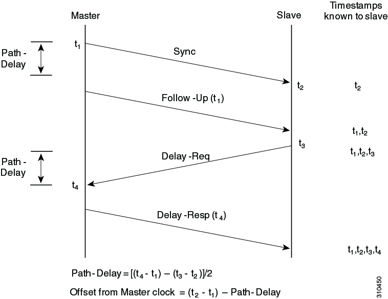
timing source. To monitor the quality of the virtual port signal, the servo mechanism in the router routinely calculates the
Time of Day (ToD) difference, or offset, between the GNSS and the best timeReceiver port. You can now configure a ToD offset
threshold value for the PTP virtual port GNSS. Threshold refers to a predefined limit or value set for the ToD offset. The
router enforces the configured threshold value upon the absolute measured offset value, without any relative adjustments or
considerations. If the offset exceeds the threshold, known as a threshold breach, the router sends alarm notifications as
syslog messages.
Threshold configuration
Suppose you intend to configure a threshold of 1000 ns for the virtual port that receives the GNSS signal. You must configure
the command as shown in the example:
Router(config-ptp-vp)#gm-threshold-breach 1000
Threshold breach
When the offset value exceeds the configured threshold value, it is referred to as a threshold breach. If the calculated offset
value is 1100 ns, it exceeds the configured threshold. Upon detecting that the virtual port has breached the threshold value,
the router sends a syslog message indicating a threshold breach. You can then analyze the syslog message and determine if
you should switch from the virtual port GNSS to selecting the best PTP timeTransmitter as a fallback source.
The router enforces the configured threshold value of 1000 ns on the absolute measured offset value of 1100 ns, without any
relative adjustments or considerations.
Sample syslog message
The alarm notification is sent as a syslog message, and it shows that the configured threshold value is 1000 ns. However,
the offset value is 1100 ns, indicating a threshold breach.
Time of day offset between virtual port and best foreign master clock aaaafffeaaaa00,
steps removed 1, receiving port 1, received on interface GigabitEthernet0/2/0/0 is 1100 ns,
configured threshold is 1000 ns. Raising virtual port offset alarm due to threshold breach.
Supported platforms
-
N540-ACC-SYS
-
N540X-ACC-SYS
-
N540-24Z8Q2C-SYS

 Feedback