Configuring VRRP
|
Feature name |
Release Information |
Feature Description |
|---|---|---|
|
Configure Additional IPv4 and IPv6 VRRP Sessions on NCS 5700 and NCS 5500 Line Cards |
Release 24.3.1 |
Introduced in this release on: NCS 5500 modular routers (NCS 5500 line cards; NCS 5700 line cards [Mode: Native]) You can now configure additional IPv4 and IPv6 VRRP sessions on the NCS 5700 and NCS 5500 line cards to improve flexibility, scalability, and control over network redundancy and load-balancing mechanisms. Earlier, you could only configure up to 255 IPv4 and 255 IPv6 VRRP sessions. However, you can now configure up to 300 IPv4 and 300 IPv6 VRRP sessions on the NCS 5700 and NCS 5500 line cards. If a physical interface reaches its limit of 255 VRRP IDs, an additional physical interface or sub-interface can accommodate the remaining 45 VRRP IDs. |
|
Support for 255 IPv4 and 255 IPv6 VRRP sessions on NCS 5700 line cards |
Release 7.3.1 |
VRRP provides failover redundancy at the first hop by grouping individual routers to form a virtual router. In this release, by default, Cisco NC57 line cards support 255 IPv4 and 255 IPv6 VRRP groups in the native mode. This feature decreases the chances of packet drops. From Release 7.0.2, this support was available only in the compatibility mode. |
The Virtual Router Redundancy Protocol (VRRP) feature allows for transparent failover at the first-hop IP router, enabling a group of routers to form a single virtual router. For more information on VRRP and related concepts, see Understanding VRRP.
Restrictions and Guidelines for Configuring VRRP
Guidelines for Configuring VRRP
Follow these guidelines for configuring VRRP:
-
From Release 24.3.1 onwards, you can configure 300 IPv4 and 300 IPv6 VRRP sessions on the NCS 5700 and NCS 5500 line cards.
You can create 1-255 VRRP sessions on a single physical interface, each supporting 1-255 VRRP IDs. If a physical interface reaches its limit of 255 VRRP IDs, you can configure an additional physical interface to accommodate the remaining 45 VRRP IDs. This method allows for the flexible reuse of VRRP IDs, enabling the configuration of 300 IPv4 and 300 IPv6 VRRP IDs as needed.
For more details on how to configure 300 IPv4 and 300 IPv6 VRRP IDs , see Configure Additional VRRP Sessions for IPv4 and IPv6 Networks.
-
By default, up to 255 IPv4 and 255 IPv6 VRRP groups are supported on Cisco NC57 line cards in the native mode. You do not need to configure the hw-module vrrpscale enable command on these line cards to enable these default number of IPv4 and IPv6 VRRP groups.
-
If you configure the command hw-module vrrpscale enable on the router, upto 255 VRRP groups (IPv4 and IPv6 combined) are supported on Cisco NCS 5500 Series Routers and Cisco NCS 540 Series routers. By default, 16 VRRP groups (IPv4 and IPv6 combined) are supported on Cisco NCS 5500 Series Routers and Cisco NCS 540 Series routers.
-
If you configure the command hw-module vrrpscale enable on the router, VRRP is only supported on sub-interfaces with dot1q encapsulation.
-
From Release 24.4.1, GRE over VRRP is supported in scale mode in NCS 5500 fixed port routers and NCS 5500 line cards. Previously, this functionality was available only in NCS 5700 fixed port routers and NCS 5700 line cards.
For more information on GRE over VRRP, see Interface and Hardware Component Configuration Guide for Cisco NCS 5500 Series Routers.
Restrictions for Configuring VRRP
These restrictions apply when you configure VRRP:
-
The VRRP scale is reduced to 13 if all the following conditions occur:
-
If you do not configure the command hw-module vrrpscale enable on the router
-
If you configure BFD along with BVI
-
If all the BVIs are sharing the same Chassis (default) MAC
-
You cannot use any custom BVI MAC in this mode until VRRP scale is reduced to 11.
-
-
ICMP redirects are not supported.
-
Protocol Independent Multicast (PIM) is not supported with VRRP.
-
The router does not support re-using VRRP ID across multiple BVIs using the same physical interface in the bridge domain.
Understanding VRRP
The Virtual Router Redundancy Protocol (VRRP) feature allows for transparent failover at the first-hop IP router, enabling a group of routers to form a single virtual router.
 Note |
VRRP is supported over VRF. |
VRRP Overview
A LAN client can use a dynamic process or static configuration to determine which router should be the first hop to a particular remote destination. The client examples of dynamic router discovery are as follows:
-
Proxy ARP—The client uses Address Resolution Protocol (ARP) to get the destination it wants to reach, and a router responds to the ARP request with its own MAC address.
-
Routing protocol—The client listens to dynamic routing protocol updates (for example, from Routing Information Protocol [RIP]) and forms its own routing table.
-
IRDP (ICMP Router Discovery Protocol) client—The client runs an Internet Control Message Protocol (ICMP) router discovery client.
The drawback to dynamic discovery protocols is that they incur some configuration and processing overhead on the LAN client. Also, in the event of a router failure, the process of switching to another router can be slow.
An alternative to dynamic Cisco Discovery Protocols is to statically configure a default router on the client. This approach simplifies client configuration and processing, but creates a single point of failure. If the default gateway fails, the LAN client is limited to communicating only on the local IP network segment and is cut off from the rest of the network.
The Virtual Router Redundancy Protocol (VRRP) feature can solve the static configuration problem. VRRP is an IP routing redundancy protocol designed to allow for transparent failover at the first-hop IP router. VRRP enables a group of routers to form a single virtual router . The LAN clients can then be configured with the virtual router as their default gateway. The virtual router, representing a group of routers, is also known as a VRRP group.
When the virtual router group IP address is the same as the IP address of the physical interface of any router in the VRRP group, then such router becomes the IP address owner and the VRRP group operates in the Owner mode. When a VRRP group operates in Owner mode, the IP address owner is responsible for forwarding packets that are sent to the VRRP group.
For operating in Owner mode in case of IPv6 VRRP sessions, the link-local address that is configured for the VRRP session must be the same as the link-local address of the physical interface in a router. The link-local address can be autoconfigured by the router or can be an address that is configured by the administrator.
For example, Basic VRRP Topology shows a LAN topology in which VRRP is configured. In this example, Routers A, B, and C are VRRP routers (routers running VRRP) that compose a virtual router. The IP address of the virtual router is the same as that configured for the interface of Router A (10.0.0.1).
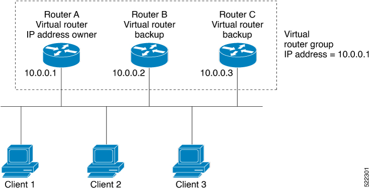
Because the virtual router uses the IP address of the physical interface of Router A, Router A assumes the role of the IP address owner and is responsible for forwarding packets that are sent to the VRRP group IP address. Clients 1 through 3 are configured with the default gateway IP address of 10.0.0.1.
Routers B and C function as backup virtual routers. If the router that is IP address owner fails, the router that is configured with the higher priority becomes the IP address owner and provides uninterrupted service for the LAN hosts. When Router A recovers, it becomes the IP address owner again.
Note |
We recommend that you disable Spanning Tree Protocol (STP) on switch ports to which the virtual routers are connected. Enable RSTP or rapid-PVST on the switch interfaces if the switch supports these protocols. |
Multiple Virtual Router Support
You can configure up to 255 virtual routers on a router interface. The actual number of virtual routers that a router interface can support depends on the following factors:
-
Router processing capability
-
Router memory capability
-
Router interface support of multiple MAC addresses
In a topology where multiple virtual routers are configured on a router interface, the interface can act as an IP address owner for one or more virtual routers and as a backup for one or more virtual routers.
VRRP Router Priority
An important aspect of the VRRP redundancy scheme is VRRP router priority. Priority determines the role that each VRRP router plays and what happens if the IP address owner virtual router fails.
If a VRRP router owns the IP address of the virtual router and the IP address of the physical interface, this router functions as a IP address owner virtual router.
If no VRRP router owns the IP address, the priority of a VRRP router, combined with the reempt settings, determines if a VRRP router functions as an IP address owner router or a backup virtual router. By default, the highest priority VRRP router functions as IP address owner router, and all the others function as backups. Priority also determines the order of ascendancy to becoming an IP address owner virtual router if the IP address owner virtual router fails. You can configure the priority of each backup virtual router with a value of 1 through 254, using the vrrp priority command.
For example, if Router A, the IP address owner virtual router in a LAN topology, fails, an election process takes place to determine if backup virtual Routers B or C should take over. If Routers B and C are configured with the priorities of 101 and 100, respectively, Router B is elected to become IP address owner virtual router because it has the higher priority. If Routers B and C are both configured with the priority of 100, the backup virtual router with the higher IP address is elected to become the IP address owner virtual router.
By default, a preemptive scheme is enabled whereby a higher-priority backup virtual router that becomes available takes over from the current IP address owner virtual router. You can disable this preemptive scheme using the vrrp preempt disable command. If preemption is disabled, the backup virtual router that is elected to become IP address owner router upon the failure of the original higher priority IP address owner router, remains the IP address owner router even if the original IP address owner virtual router recovers and becomes available again.
VRRP Advertisements
The IP address owner virtual router sends VRRP advertisements to other VRRP routers in the same group. The advertisements communicate the priority and state of the IP address owner virtual router. The VRRP advertisements are encapsulated in IP packets and sent to the IP Version 4 multicast address assigned to the VRRP group. The advertisements are sent every second by default; the interval is configurable.
Benefits of VRRP
The benefits of VRRP are as follows:
-
Redundancy— VRRP enables you to configure multiple routers as the default gateway router, which reduces the possibility of a single point of failure in a network.
-
Load Sharing—You can configure VRRP in such a way that traffic to and from LAN clients can be shared by multiple routers, thereby sharing the traffic load more equitably among available routers.
-
Multiple Virtual Routers—VRRP supports up to 100 virtual routers (VRRP groups) on a router interface, subject to the platform supporting multiple MAC addresses. You can configure up to 256 virtual routers on a router interface. Multiple virtual router support enables you to implement redundancy and load sharing in your LAN topology.
-
Multiple IP Addresses—The virtual router can manage multiple IP addresses, including secondary IP addresses. Therefore, if you have multiple subnets configured on an Ethernet interface, you can configure VRRP on each subnet.
-
Preemption—The redundancy scheme of VRRP enables you to preempt a backup virtual router that has taken over for a failing IP address owner virtual router with a higher-priority backup virtual router that has become available.
-
Text Authentication—You can ensure that VRRP messages received from VRRP routers that comprise a virtual router are authenticated by configuring a simple text password.
-
Advertisement Protocol—VRRP uses a dedicated Internet Assigned Numbers Authority (IANA) standard multicast address (224.0.0.18) for VRRP advertisements. This addressing scheme minimizes the number of routers that must service the multicasts and allows test equipment to accurately identify VRRP packets on a segment. The IANA assigns VRRP the IP protocol number 112.
Hot Restartability for VRRP
In the event of failure of a VRRP process in one group, forced failovers in peer VRRP IP address owner router groups should be prevented. Hot restartability supports warm RP failover without incurring forced failovers to peer VRRP routers.
Understanding VRRP over BVI
The Virtual Router Redundancy Protocol (VRRP) protocol provides default gateway redundancy. It allows a group of routers to behave as a single virtual default gateway router in which one router acts as the IP address owner router and others routers act as Backup routers.
BVI (Bridge-Group Virtual Interface) is a virtual interface which provides L3 or routed functionality to a Bridge Group. L2 functionality is applicable to the interfaces which are part of a Bridge Group and BVI is the routed interface for that Bridge Group.
Usually, VRRP sessions run on top of interfaces of the multiple routers which are in the same home network. However, you can configure VRRP session over BVI. Thereby, instead of physical interfaces, VRRP sessions can run between BVI interfaces of multiple routers.
Configuring VRRP for IPv4 Networks
This section describes the procedure for configuring and verifying VRRP for IPv4 networks.
Configuration
Use the following configuration for configuring VRRP for IPv4 networks.
Note |
Certain customizations (as mentioned) are recommended to control the behavior of the VRRP group on committing the VRRP configuration on the Router. If the following customizations are not configured, then the router seizes control of the VRRP group, and immediately assumes the role of the IP address owner virtual router. |
/* Enter the interface configuration mode and configure an IPv4 address for the interface. */
Router(config)# interface gigabitEthernet 0/0/0/1
Router(config-if)# ipv4 address 10.10.10.1 255.255.255.0
Router(config-if)# no shut
Router(config-if)# commit
Fri Dec  8 13:49:24.142 IST
Router:Dec  8 13:49:24.285 : ifmgr[402]: %PKT_INFRA-LINK-3-UPDOWN : Interface GigabitEthernet0/0/0/1, changed state to Down
Router:Dec  8 13:49:24.711 : ifmgr[402]: %PKT_INFRA-LINK-3-UPDOWN : Interface GigabitEthernet0/0/0/1, changed state to Up

Router(config-if)# exit
Router(config)# do show ip int brief
Fri Dec  8 13:50:05.505 IST

Interface                          IP-Address         Status             Protocol    Vrf-Name
GigabitEthernet0/0/0/0             unassigned         Shutdown           Down        default
GigabitEthernet0/0/0/1          10.10.10.1         Up                 Up          default
GigabitEthernet0/0/0/2             unassigned         Shutdown           Down        default
GigabitEthernet0/0/0/3             unassigned         Shutdown           Down        default
GigabitEthernet0/0/0/4             unassigned         Shutdown           Down        default


/* Enter the VRRP configuration mode and add the configured interface. */
Router(config)# router vrrp
Router(config-vrrp)# interface GigabitEthernet 0/0/0/1

/* CUSTOMIZATION: Configure a delay for the startup of the state machine when the interface comes up. */
Router(config-vrrp)# delay minimum 2 reload 10 */

/* Configure VRRP version 3 for IPv4 */
Router(config-vrrp-if)# address-family ipv4 vrrp 100 version 3
Router(config-vrrp-virtual-router)# address 10.10.10.1

/* CUSTOMIZATION: Disable the installation of routes for the VRRP virtual addresses. */
Router(config-vrrp-virtual-Router)# accept-mode disable

/* CUSTOMIZATION: Set a priority for the virtual Router. */
Router(config-vrrp-virtual-Router)# priority 254

/* CUSTOMIZATION: Configure a preempt delay value that controls the selection of the IP address owner virtual Router. */
Router(config-vrrp-virtual-Router)# preempt delay 15

/* CUSTOMIZATION: Configure the interval between successive advertisements by the IP address owner virtual Router. */
Router(config-vrrp-virtual-Router)#timer 4

/* CUSTOMIZATION: Configure VRRP to track an interface. */
Router(config-vrrp-virtual-Router)# track interface GigabitEthernet0/0/0/1 30

 /* Commit the configuration */
Router(config-vrrp-virtual-Router)# commit
–––––––––––––––––––––––––––––––––––––––––––––––––––––––––––––––––––––––––––––––––––––––––––––––––––––––––––––––––-
You have successfully configured VRRP for IPv4 networks.
Validation
Use the following commands to validate the configuration.
/* Validate the configuration */
Router(config-vrrp-virtual-router)# do show run interface GigabitEthernet 0/0/0/1
Fri Dec  8 15:04:38.140 IST
interface GigabitEthernet0/0/0/1
 ipv4 address 10.10.10.1 255.255.255.0
!

–––––––––––––––––––––––––––––––––––––––––––––––––––––––––––––––––––––––––––––––––––––––––––––––––––––––––––––––--
Router(config)# show running-config router vrrp
Fri Dec  8 13:50:18.959 IST
router vrrp
 interface GigabitEthernet0/0/0/1
   delay minimum 2 reload 10
  address-family ipv4
   vrrp 100 version 3
    priority 254
    preempt delay 15
    timer 4
    track interface GigabitEthernet0/0/0/2 30
    address 10.10.10.1
    accept-mode disable
   !
  !
 !
–––––––––––––––––––––––––––––––––––––––––––––––––––––––––––––––––––––––––––––––––––––––––––––––––––––––––––––––––––––––--
Router(config-vrrp-virtual-router)# do show vrrp ipv4 interface gigabitEthernet 0/0/0/1
Fri Dec  8 15:02:56.952 IST
IPv4 Virtual Routers:
                      A indicates IP address owner
                      | P indicates configured to preempt
                      | |
Interface   vrID Prio A P State    Master addr     VRouter addr
Gi0/0/0/1    100  255 A P Master   local           10.10.10.1

––––––––––––––––––––––––––––––––––––––––––––––––––––––––––––––––––––––––––––––––––––––––––––––––––––––––––––––––––––––--
Router(config-vrrp-virtual-router)# end
Router# show vrrp detail
Fri Dec  8 15:08:36.469 IST
GigabitEthernet0/0/0/1 - IPv4 vrID 100
  State is Master, IP address owner
    1 state changes, last state change 01:19:06
    State change history:
    Dec  8 13:49:30.147 IST  Init     -> Master   Delay timer expired
  Last resign sent:     Never
  Last resign received: Never
  Virtual IP address is 10.10.10.1
  Virtual MAC address is 0000.5E00.0164, state is active
  Master router is local
  Version is 3
  Advertise time 1 secs
    Master Down Timer 3.003 (3 x 1 + (1 x 1/256))
  Minimum delay 1 sec, reload delay 5 sec
  Current priority 255
    Configured priority 100, may preempt
      minimum delay 0 secs
You have successfully validated VRRP for IPv4 networks.
Configuring VRRP for IPv6 Networks
This section describes the procedure for configuring and verifying VRRP for IPv6 networks.
Configuration
The following sample includes the configuration and customization of VRRP for IPv6 networks.
Note |
Certain customizations (as mentioned) are recommended to control the behavior of the VRRP group on committing the VRRP configuration on the Router. If the following customizations are not configured, then the Router seizes control of the VRRP group, and immediately assumes the role of the IP address owner virtual Router. |
/* Enter the interface configuration mode and configure an IPv6 address */
Router# interface GigabitEthernet 0/0/0/2
Router(config-if)# ipv6 address 10::1/64
Router(config-if)# no shut

/* Exit the interface configuration mode and enter the vrrp configuration mode */
Router(config-if)# exit
Router(config)# Router vrrp

/* Add the configured interface for VRRP */
Router(config-vrrp)# interface GigabitEthernet 0/0/0/2

/* CUSTOMIZATION: Configure a delay for the startup of the state machine when the interface comes up. */
Router(config-vrrp)# delay minimum 2 reload 10 */

/* Enable the IPv6 global and link local address family on the interface  */
Router(config-vrrp-if)# address-family ipv6 vrrp 50
Router(config-vrrp-virtual-Router)# address linklocal autoconfig

/* CUSTOMIZATION: Disable the installation of routes for the VRRP virtual addresses. */
Router(config-vrrp-virtual-Router)# accept-mode disable

/* CUSTOMIZATION: Set a priority for the virtual Router. */
Router(config-vrrp-virtual-Router)# priority 254

/* CUSTOMIZATION: Configure a preempt delay value that controls the selection of the IP address owner virtual Router. */
Router(config-vrrp-virtual-Router)# preempt delay 15

/* CUSTOMIZATION: Configure the interval between successive advertisements by the IP address owner virtual Router. */
Router(config-vrrp-virtual-Router)#timer 4

/* CUSTOMIZATION: Configure VRRP to track an interface. */
Router(config-vrrp-virtual-Router)# track interface GigabitEthernet0/0/0/2 30

/* Commit the configuration */
Router(config-vrrp-virtual-Router)# commit
You have successfully configured VRRP for IPv6 networks.
Validation
Use the following commands to validate the configuration.
/* Validate the configuration */
Router(config-vrrp-virtual-router)# do show run interface GigabitEthernet 0/0/0/2
Fri Dec  8 14:55:48.378 IST
interface GigabitEthernet0/0/0/2
 ipv6 address 10::1/64
!
––––––––––––––––––––––––––––––––––––––––––––––––––––––––––––––––––––––––––––––––––––––––––––––––––––––––––––––-
Router(config-vrrp-virtual-router)# do show running-config router vrrp
...
router vrrp
 interface GigabitEthernet0/0/0/2
  delay minimum 2 reload 10
  address-family ipv6
   vrrp 50
    priority 254
    preempt delay 15
    timer 4
    track interface GigabitEthernet0/0/0/2 30
    address linklocal autoconfig
    accept-mode disable
   !
  !
 !
!
––––––––––––––––––––––––––––––––––––––––––––––––––––––––––––––––––––––––––––––––––––––––––––––––––––––––––––––––––––-
Router(config-vrrp-virtual-router)# do show vrrp ipv6 interface gigabitEthernet 0/0/0/2
Fri Dec  8 14:59:25.547 IST
IPv6 Virtual Routers:
                      A indicates IP address owner
                      | P indicates configured to preempt
                      | |
Interface   vrID Prio A P State    Master addr     VRouter addr
Gi0/0/0/2      50  254   P Master   local
                                               fe80::200:5eff:fe00:203

––––––––––––––––––––––––––––––––––––––––––––––––––––––––––––––––––––––––––––––––––––––––––––––––––––––––––––––––––––––-
Router(config-vrrp-virtual-router)# end
Router# show vrrp detail
Fri Dec  8 15:08:36.469 IST
GigabitEthernet0/0/0/2 - IPv6 vrID 50
  State is Master
    2 state changes, last state change 00:18:01
    State change history:
    Dec  8 14:50:23.326 IST  Init     -> Backup   Virtual IP configured
    Dec  8 14:50:35.365 IST  Backup   -> Master   Master down timer expired
  Last resign sent:     Never
  Last resign received: Never
  Virtual IP address is fe80::200:5eff:fe00:203
  Virtual MAC address is 0000.5E00.0203, state is active
  Master router is local

  Advertise time 4 secs
    Master Down Timer 12.031 (3 x 4 + (2 x 4/256))
  Minimum delay 2 sec, reload delay 10 sec
  Current priority 254
    Configured priority 254, may preempt
      minimum delay 15 secs
    Tracked items: 1/1 up: 0 decrement
      Object name                State     Decrement
      GigabitEthernet0/0/0/2        Up            30
You have successfully validated VRRP for IPv6 networks.
Configure Additional VRRP Sessions for IPv4 and IPv6 Networks
To configure 300 IPv4 and IPv6 VRRP sessions on the NCS 5700 line cards and NCS 5500 line cards, configure 1-255 VRRP IDs on one physical interface or sub-interface, and configure the remaining 45 VRRP sessions on another physical interface or sub-interface.
For example, consider a physical interface, 0/3/0/21.1. Configure 0/3/0/21.1 through 0/3/0/21.255 physical interfaces to configure 255 VRRP sessions.
To configure the remaining 45 physical interfaces, repeat the configuration steps on a different physical interface, such as 0/3/0/23.1, and configure the interfaces from 0/3/0/23.1 through 0/3/0/23.45.
By following these steps, you will have successfully configured a total of 300 VRRP sessions across the specified interfaces.
For detailed information on the configuration steps and validation, see Configuring VRRP for IPv4 Networks and Configuring VRRP for IPv6 Networks.
Unicast VRRP
|
Feature Name |
Release Name |
Description |
|---|---|---|
|
Unicast VRRP |
Release 7.11.1 | Introduced in this release on: NCS 5500 modular routers (NCS 5500 line cards). We have now enabled Layer 3 unicast transport mode in VRRP, allowing it to enhance its capacity to send data to other networks, including cloud networks. Pairwise router redundancy enables high availability in cloud network scenarios. However, a virtual IP (VIP) address is required by the default route of the cloud native function because there is no pre-designated active member in paired routers. HSRP can provide a VIP, but cloud networks do not support Layer 2 multicast or broadcast transports. You can configure VRRP to support Layer 3 unicast transport to overcome the limitation of Layer 2 multicast and broadcast transports. The feature introduces these changes: New Command: CLI: Modified Commands:
YANG Data Model: New Xpaths for:
|
You can now configure VRRP to support Layer 3 unicast transport, allowing it to enhance its capacity to send data to cloud networks. Pairwise router redundancy enables high availability in cloud network scenarios. The default route of the cloud native function needs a virtual IP (VIP) address because the paired routers do not have a pre-designated active member. Though HSRP provides a VIP, the cloud networks do not support Layer 2 multicast or broadcast transports. To overcome the limitations of Layer 2 multicast and broadcast transports, configure VRRP in Layer 3 unicast mode to support Layer 3 unicast transport.
This feature also enables VRRP to communicate state transition notifications using event-driven telemetry.
Restrictions for Unicast VRRP
-
When you configure the unicast-peer command, the router neither sends nor receives multicast packets.
-
You can configure the unicast-peer command only once, allowing for the participation of only two physical routers in a unicast VRRP session.
Configure Unicast VRRP
Configuration Example
The following example shows how to enable unicast transport through VRRP.
Router(config)# router vrrp
Router(config-vrrp)# interface GigabitEthernet0/0/0/0
Router(config-vrrp-if)# address-family ipv4
Router(config-vrrp-address-family)# vrrp 1
/* Configure the virtual IP address on the interface. */
Router(config-vrrp-virtual-router)# address 10.0.1.100
/* Configure the unicast-peer command to enable IPv4 unicast transport. */
Router(config-vrrp-virtual-router)# unicast-peer 10.0.1.1
Router(config-vrrp-virtual-router)# exit
Router(config-vrrp-address-family)# exit
Router(config-vrrp-if)# address-family ipv6
Router(config-vrrp-address-family)# vrrp 2
/* Configure the unicast-peer command to enable IPv6 unicast transport.  */
Router(config-vrrp-virtual-router)# unicast-peer FE80::260:3EFF:FE11:6770
Router(config-vrrp-virtual-router)# exit
Router(config-vrrp-address-family)# exit
Running Configuration
router vrrp
 interface GigabitEthernet0/0/0/0
  address-family ipv4
   vrrp 1
    address 10.0.0.100
    unicast-peer 10.0.1.1
   !
  !
  address-family ipv6
   vrrp 2
    unicast-peer  FE80::260:3EFF:FE11:6770
   !
  !
 !
!
Verification
Use the following command to verify if the unicast transport enabled in VRRP. The output shows that both IPv4 and IPv6 unicast peers have been configured, and the respective IP addresses are displayed.
Router# show vrrp detail
Fri Sep  8 15:02:35.268 IST
GigabitEthernet0/0/0/0 - IPv4 vrID 1
  State is Master
    2 state changes, last state change 04:00:02
    State change history:
    Sep  8 11:02:29.518 IST  Init     -> Backup   Virtual IP configured
    Sep  8 11:02:33.127 IST  Backup   -> Master   Master down timer expired
  Last resign sent:     Never
  Last resign received: Never
  Virtual IP address is 10.0.0.100
  Virtual MAC address is 0000.5E00.0101, state is active
  Master router is local
  Version is 2
  Advertise time 1 secs
    Master Down Timer 3.609 (3 x 1 + (156 x 1/256))
  Minimum delay 1 sec, reload delay 5 sec
  Current priority 100
    Configured priority 100, may preempt
      minimum delay 0 secs
  IPv4 Unicast Peer: 10.0.1.1 --> IPv4 unicast transport is enabled on VRRP.

GigabitEthernet0/0/0/0 - IPv6 vrID 2
  State is Init
    0 state changes, last state change never
    State change history:
  Last resign sent:     Never
  Last resign received: Never
  Virtual IP address is ::
  Virtual MAC address is 0000.5E00.0202, state is stored
  Master router is unknown
  Version is 3
  Advertise time 1 secs
    Master Down Timer 3.609 (3 x 1 + (156 x 1/256))
  Minimum delay 1 sec, reload delay 5 sec
  Current priority 100
    Configured priority 100, may preempt
      minimum delay 0 secs
  IPv6 Unicast Peer: FE80::260:3EFF:FE11:6770 --> IPv6 unicast transport is enabled on VRRP.
Use the following command to verify detailed statistics about the Virtual Router VRRP configuration. Note that the number of multicast packets received in the VRRP instance when it's configured to function in unicast mode is zero.
Router# show vrrp statistics
Fri Sep  8 15:03:03.521 IST
Invalid packets:
  Invalid checksum:                     0
  Unknown/unsupported versions:         0
  Invalid vrID:                         0
  Too short:                            0
Protocol:
  Transitions to Master                 1
Packets:
  Total received:                       0
  Adverts sent:                     14476
  Bad TTL:                              0
  Short Packets:                        0
  Failed authentication:                0
  Unknown authentication:               0
  Conflicting authentication:           0
  Unknown Type field:                   0
  Conflicting Advertise time:           0
  Conflicting Addresses:                0
  Received with zero priority:          0
  Sent with zero priority:              0
 Mcast packet in Ucast mode:           0 --> Multicast packet being received in unicast mode.
Configure VRRP over BVI
To configure VRRP sessions over BVI, you must complete the following configurations:
Note |
The VRRP sessions over BVI traffic are not supported with IRB processing in two-pass model on ingress. |
-
Configure a set of interfaces as L2 interfaces and a set of VLAN sub-interfaces.
-
Configure a bridge group.
-
Configure a BVI.
-
Configure VRRP over BVI.
Configuration Example
/* Enter the global configuration mode and Configure a set of interfaces as L2 interfaces and a set of VLAN sub-interfaces */
Router# configure
Router(config)# interface HundredGigE0/0/1/0.1 l2transport
Router(config-subif)# encapsulation dot1q 1
Router(config-subif)# rewrite ingress tag pop 1 symmetric
Router(config-subif)# commit
Router(config-subif)# exit
Router(config)# interface HundredGigE0/0/1/1.1 l2transport
Router(config-subif)# encapsulation dot1q 1
Router(config-subif)# rewrite ingress tag pop 1 symmetric
Router(config-subif)# commit
Router(config-subif)# exit

/* Enter the Layer 2 VPN configuration mode and Configure a bridge group */
Router(config)# l2vpn
Router(config-l2vpn)# bridge group 5
Router(config-l2vpn-bg)# bridge-domain 5
Router(config-l2vpn-bg-bd)# interface HundredGigE 0/0/0/0.1
Router(config-l2vpn-bg-bd-ac)# exit
Router(config-l2vpn-bg-bd)# interface HundredGigE 0/0/0/1.1
Router(config-l2vpn-bg-bd-ac)# exit
Router(config-l2vpn-bg-bd)# routed interface BVI 10
Router(config-l2vpn-bg-bd-bvi)# commit
Router(config-l2vpn-bg-bd-bvi)# exit

/* Configure a BVI in the global configuration mode*/
Router(config-l2vpn-bg-bd)# interface BVI 10

Router(config-if)# ipv4 address 209.165.200.225 255.255.255.0
Router(config-if)# ipv6 address 2001:DB8:A:B::1/64
Router(config-if)# commit

/* Configure VRRP over BVI in the global configuration mode for IPv4 address*/
Router(config)# router VRRP
Router(config-vrrp)# interface BVI 10
Router(config-vrrp-if)# address-family ipv4
Router(config-vrrp-address-family)# VRRP 10
Router(config-vrrp-virtual-router)# priority 101
Router(config-vrrp-virtual-router)# address 209.165.200.226
Router(config-vrrp-virtual-router)# commit


/* Configure VRRP over BVI in the global configuration mode for IPv6 address*/
Router(config)# router VRRP
Router(config-vrrp)# interface BVI 10
Router(config-vrrp-if)# address-family ipv6
Router(config-vrrp-address-family)# VRRP 11
Router(config-vrrp-virtual-router)# address global 2001:DB8:A:B::2
Router(config-vrrp-virtual-router)#  address linklocal autoconfig
Router(config-vrrp-virtual-router)# commit
Verification
Use the following command to verify the bridge domain details:
Router# show l2vpn bridge-domain detail

Legend: pp = Partially Programmed.
Bridge group: 5, bridge-domain: 5, id: 1, state: up, ShgId: 0, MSTi: 0
Coupled state: disabled
VINE state: BVI Resolved
MAC learning: enabled
MAC withdraw: enabled
MAC withdraw for Access PW: enabled
MAC withdraw sent on: bridge port up
MAC withdraw relaying (access to access): disabled
Flooding:
Broadcast & Multicast: enabled
Unknown unicast: enabled
MAC aging time: 300 s, Type: inactivity
MAC limit: 32768, Action: none, Notification: syslog
MAC limit reached: no, threshold: 75%
MAC port down flush: enabled
MAC Secure: disabled, Logging: disabled
Split Horizon Group: none
Dynamic ARP Inspection: disabled, Logging: disabled
IP Source Guard: disabled, Logging: disabled
DHCPv4 Snooping: disabled
DHCPv4 Snooping profile: none
IGMP Snooping: disabled
IGMP Snooping profile: none
MLD Snooping profile: none
Storm Control: disabled
Bridge MTU: 1500
MIB cvplsConfigIndex: 2
Filter MAC addresses:
P2MP PW: disabled
Multicast Source: Not Set
Create time: 26/05/2020 17:08:54 (00:11:30 ago)
No status change since creation
ACs: 3 (3 up), VFIs: 0, PWs: 0 (0 up), PBBs: 0 (0 up), VNIs: 0 (0 up)
List of ACs:
AC: BVI10, state is up
Type Routed-Interface
MTU 1514; XC ID 0x80000001; interworking none
BVI MAC address:
c472.95a6.8b90
Virtual MAC addresses:
0000.5e00.010a
0000.5e00.020b
Split Horizon Group: Access
AC: HundredGigE0/0/1/0.1, state is up
Type VLAN; Num Ranges: 1
Rewrite Tags: []
VLAN ranges: [1, 1]
MTU 1500; XC ID 0x1; interworking none
MAC learning: enabled
Flooding:
Broadcast & Multicast: enabled
Unknown unicast: enabled
MAC aging time: 300 s, Type: inactivity
MAC limit: 32768, Action: none, Notification: syslog
MAC limit reached: no, threshold: 75%
MAC port down flush: enabled
MAC Secure: disabled, Logging: disabled
Split Horizon Group: none
E-Tree: Root
Dynamic ARP Inspection: disabled, Logging: disabled
IP Source Guard: disabled, Logging: disabled
DHCPv4 Snooping: disabled
DHCPv4 Snooping profile: none
IGMP Snooping: disabled
IGMP Snooping profile: none
MLD Snooping profile: none
Storm Control: bridge-domain policer
Static MAC addresses:
Statistics:
packets: received 0 (multicast 0, broadcast 0, unknown unicast 0, unicast 0), sent 1435
bytes: received 0 (multicast 0, broadcast 0, unknown unicast 0, unicast 0), sent 114828
MAC move: 0
Storm control drop counters:
packets: broadcast 0, multicast 0, unknown unicast 0
bytes: broadcast 0, multicast 0, unknown unicast 0
Dynamic ARP inspection drop counters:
packets: 0, bytes: 0
IP source guard drop counters:
packets: 0, bytes: 0
AC: HundredGigE0/0/1/1.1, state is up
Type VLAN; Num Ranges: 1
Rewrite Tags: []
VLAN ranges: [1, 1]
MTU 1500; XC ID 0x2; interworking none
MAC learning: enabled
Flooding:
Broadcast & Multicast: enabled
Unknown unicast: enabled
MAC aging time: 300 s, Type: inactivity
MAC limit: 32768, Action: none, Notification: syslog
MAC limit reached: no, threshold: 75%
MAC port down flush: enabled
MAC Secure: disabled, Logging: disabled
Split Horizon Group: none
E-Tree: Root
Dynamic ARP Inspection: disabled, Logging: disabled
IP Source Guard: disabled, Logging: disabled
DHCPv4 Snooping: disabled
DHCPv4 Snooping profile: none
IGMP Snooping: disabled
IGMP Snooping profile: none
MLD Snooping profile: none
Storm Control: bridge-domain policer
Static MAC addresses:
Statistics:
packets: received 0 (multicast 0, broadcast 0, unknown unicast 0, unicast 0), sent 1435
bytes: received 0 (multicast 0, broadcast 0, unknown unicast 0, unicast 0), sent 114828
MAC move: 0
Storm control drop counters:
packets: broadcast 0, multicast 0, unknown unicast 0
bytes: broadcast 0, multicast 0, unknown unicast 0
Dynamic ARP inspection drop counters:
packets: 0, bytes: 0
IP source guard drop counters:
packets: 0, bytes: 0
List of Access PWs:
List of VFIs:
List of Access VFIs:
Use the following command to show the VRRP details:
Router# show vrrp ipv4 detail

BVI10 - IPv4 vrID 10
State is Master
2 state changes, last state change 00:11:57
State change history:
May 26 17:08:59.470 UTC Init -> Backup Delay timer expired
May 26 17:09:03.075 UTC Backup -> Master Master down timer expired
Last resign sent: Never
Last resign received: Never
Virtual IP address is 209.165.200.226
Virtual MAC address is 0000.5E00.010a, state is active
Master router is local
Version is 2
Advertise time 1 secs
Master Down Timer 3.605 (3 x 1 + (155 x 1/256))
Minimum delay 1 sec, reload delay 5 sec
Current priority 101
Configured priority 101, may preempt
minimum delay 0 secs
Router# show vrrp ipv6 detail
BVI10 - IPv6 vrID 11
State is Master
2 state changes, last state change 00:04:29
State change history:
May 26 17:16:43.476 UTC Init -> Backup Virtual IP configured
May 26 17:16:47.085 UTC Backup -> Master Master down timer expired
Last resign sent: Never
Last resign received: Never
Virtual IP address is fe80::200:5eff:fe00:20b
Secondary Virtual IP address is 2001:db8:a:b::2
Virtual MAC address is 0000.5E00.020b, state is active
Master router is local
Version is 3
Advertise time 1 secs
Master Down Timer 3.609 (3 x 1 + (156 x 1/256))
Minimum delay 1 sec, reload delay 5 sec
Current priority 100
Configured priority 100, may preempt
minimum delay 0 secsRouter# show vrrp interface BVI10 detail
BVI10 - IPv4 vrID 10
State is Master
2 state changes, last state change 00:12:35
State change history:
May 26 17:08:59.470 UTC Init -> Backup Delay timer expired
May 26 17:09:03.075 UTC Backup -> Master Master down timer expired
Last resign sent: Never
Last resign received: Never
Virtual IP address is 209.165.200.226
Virtual MAC address is 0000.5E00.010a, state is active
Master router is local
Version is 2
Advertise time 1 secs
Master Down Timer 3.605 (3 x 1 + (155 x 1/256))
Minimum delay 1 sec, reload delay 5 sec
Current priority 101
Configured priority 101, may preempt
minimum delay 0 secs
BVI10 - IPv6 vrID 11
State is Master
2 state changes, last state change 00:04:51
State change history:
May 26 17:16:43.476 UTC Init -> Backup Virtual IP configured
May 26 17:16:47.085 UTC Backup -> Master Master down timer expired
Last resign sent: Never
Last resign received: Never
Virtual IP address is fe80::200:5eff:fe00:20b
Secondary Virtual IP address is 2001:db8:a:b::2
Virtual MAC address is 0000.5E00.020b, state is active
Master router is local
Version is 3
Advertise time 1 secs
Master Down Timer 3.609 (3 x 1 + (156 x 1/256))
Minimum delay 1 sec, reload delay 5 sec
Current priority 100
Configured priority 100, may preempt
minimum delay 0 secsBFD for VRRP
Bidirectional Forwarding Detection (BFD) is a network protocol used to detect faults between two forwarding engines. BFD sessions operate in asynchronous mode. In asynchronous mode, both endpoints periodically send hello packets to each other. If a number of those packets are not received, the session is considered down.
Advantages of BFD
-
BFD provides failure detection in less than one second.
-
BFD supports all types of encapsulation.
-
BFD is not tied to any particular routing protocol, supports almost all routing protocols.
BFD Process
VRRP uses BFD to detect a link failure and facilitate fast failover times without excessive control packet overhead.
The VRRP process creates BFD sessions as required. When a BFD session goes down, each backup group monitoring the session transitions to the active state.
Note |
IPv4 only supports BFD for VRRP. |
Configuring BFD
Enabling BFD
Router#
configure
Router(config)# router vrrp
Router(config-vrrp)# interface <type> <interface-path-id>
Router(config-vrrp-if)# address-family ipv4
Router(config-vrrp-ipv4)# vrrp[group number] version <version-no> bfd fast-detect [peer ipv4 <ipv4-address> <interface-type> <interface-path-id>]
commit
Verifying BFD on VRRP
router vrrp

interface TenGigE0/0/0/3.1

bfd minimum-interval 4

bfd multiplier 3

address-family ipv4

vrrp 1

priority 200

address 41.41.1.3

bfd fast-detect peer ipv4 41.41.1.2
Modifying BFD timers (minimum interval)
Minimum interval determines the frequency of sending BFD packets to BFD peers (in milliseconds). The default minimum interval is 15ms.
Router#
configure
Router(config)# router vrrp
Router(config-vrrp)# interface <type> <interface-path-id>
Router(config-vrrp-if)# bfd minimum-interval <interval>
Router(config-vrrp-if)# bfd multiplier <multiplier>
router(config-vrrp-if)# address-family ipv4
commit
Modifying BFD timers (multiplier)
Multiplier is the number of consecutive BFD packets which must be missed from a BFD peer before declaring that peer unavailable. The default multiplier is 3.
Router#
configure
Router(config)# router vrrp
Router(config-vrrp)# interface <type> <interface-path-id>
Router(config-vrrp-if)# bfd multiplier <multiplier>
router(config-vrrp-if)# address-family ipv4
commit
Disabling State Change Logging
Configuration Example
Disables the task of logging the VRRP state change events via syslog.
Router#configure
Router(config)#router vrrp
router(config-vrrp)#message state disable
router(config-vrrp)#commit
 Feedback