Install the Chassis


Note


The images in this chapter are only for representation purposes, unless specified otherwise. The chassis' actual appearance and size may vary.


Unpack the Chassis


Tip


Be sure to save the packaging in case you need to return any of the components product.

Ensure there is sufficient room around the chassis pallet for unpacking. For information about the chassis dimensions and clearance requirements see, Clearance Requirements.

Carefully move the pallet containing the chassis to the staging area where you plan on unpacking it.

Leave the chassis on the pallet until you are ready to move and install the chassis in a rack.

Install Bottom-Support Rails

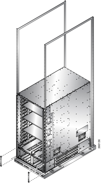
The bottom-support rails support the weight of the router chassis in the rack. To maximize the stability of the rack, you must attach these rails at the lowest possible rack unit (RU).

Procedure


Step 1

Position one of the two adjustable bottom-support rails at the lowest possible RU in the rack and adjust the length of each rail so that it stretches from the outer edges of the front and rear vertical mounting rails on the rack. Check spacing considerations.

Note

 
You can expand the rail so that its mounting brackets are spaced between 24 to 32 inches (61.0 to 81.3 cm).
Figure 1. Position Bottom-Support Rails

1

Position two bottom-support rails at the lowest RU on the rack.

2

NCS 5504: Allow at least 7.1 RU (12.43 inches [31.6 cm]) for each chassis.

NCS 5508: Allow at least 13 RU (22.7 in [57.8 cm]) for each chassis.

NCS 5516: Allow at least 21 (36.7 in [93.21 cm]) RU for each chassis.

3

Distance between front and rear vertical rails must be 24 to 32 inches (61.0 to 81.3 cm).

Step 2

Attach the bottom-support rail to the rack using a Phillips torque screwdriver on three M6 x 19 mm or 12-24 x 3/4 inch screws for each end of the rail (using a total of 6 screws for the rail as shown in the following figure) and tighten each screw to 40 in-lbs (4.5 N.m) of torque.

Figure 2. Attach Bottom-Support Rails to a Rack

1

Adjustable bottom-support rails (2)

2

M6 x 19 mm (or 12-24 x 3/4 in.) Phillips screws (at least 6 per rail)

Note

 
Use at least three screws on each end of each bottom-support rail.

Step 3

Repeat Steps 1 and 2 to attach the other bottom-support rail to the rack.

Note

 
Make sure that the two bottom-support rails are level with one another. If they are not level, adjust the higher rail down to the level of the lower rail.

What to do next

Mount the chassis into the rack.

Transfer Chassis to a Mechanical Lifting Device

Procedure


Step 1

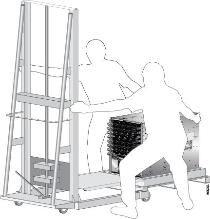
Place the mechanical lifting device in front of the chassis on the pallet (PLIM side) as shown in Align the Lifting Device In Front of the Chassis on the Pallet .

Figure 3. Align the Lifting Device In Front of the Chassis on the Pallet

Step 2

Prepare to use the mechanical lifting device by placing a piece of cardboard on the surface of the lift (to prevent scratching).

Step 3

With at least two or three people move the chassis carefully from the pallet onto the lifting device as shown in Move the Chassis On To the Lifting Device .

Figure 4. Move the Chassis On To the Lifting Device

Step 4

Using two people; lift the box straight up over the chassis.

Step 5

Leave the chassis on the pallet until you are ready to move and install the chassis in a rack.


What to do next

After moving the chassis to the room or area where you will install it, begin the procedure to mount the chassis into the rack.

(Optional) Install the Rear Chassis Brackets

Before you begin

This procedure is required only to install door kit, which is optional.

Procedure


Step 1

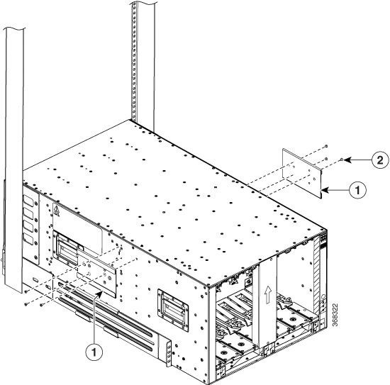
To install the chassis on a 4-post 635 mm rack, attach the bracket as follows:

  1. Align the side bracket so that it is flush with the top of the chassis. See the figure below-

    1

    Side brackets

    2

    Screws

    Note

     
    The side brackets are not part of the rack mount kit. If you want to adhere to NEBS compliance, you must install the side brackets that are orderable as part of NEBS door kit.
  2. Use 6 M4 screws with 12 in-lbs (1.4 N-m) to attach the side bracket to the chassis.

  3. Repeat a and b on the other side of the chassis.

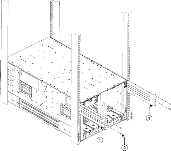
  4. Slide the rack-mount bracket through the side bracket.

    1

    Rack mount brackets

    2

    Screws
  5. Use 4 M6 x 19 mm (or 12-24 x 3/4 in.) Phillips screws tighten each screw to (4.5 N-m) 40 in-lbs of torque to attach the bracket to the chassis.

  6. Repeat d through e on the other side of the chassis.

Step 2

To install the chassis on a 4-post 780 mm rack, attach the bracket as follows:

  1. Align the side bracket so that it is flush with the top of the chassis. See the figure below-

    1

    Side brackets

    2

    Screws
  2. Use 4 M6 screws with (4.5 N-m) 40 in-lbs of torque to attach the side bracket to the chassis.

  3. Repeat a and b on the other side of the chassis.

  4. Slide the rack mount bracket through the side bracket.

    1

    Rack mount brackets

    2

    Screws
  5. Use 4 M6 x 19 mm (or 12-24 x 3/4 in.) Phillips screws tighten each screw to (4.5 N-m) 40 in-lbs of torque to attach the bracket to the chassis.

  6. Repeat d and e on the other side of the chassis.


What to do next

After installing the rear chassis brackets, begin the procedure to mount the chassis into the rack.

Mount Chassis Into the Rack

To accommodate equipment racks with different mounting hole patterns, the chassis mounting brackets have groups of screw holes on either side. The mounting holes in the chassis mounting brackets are spaced so that one mounting hole in each hole group aligns with a corresponding hole in the equipment rack or the optional center-mount bracket. By using the corresponding mounting hole (in the same hole group) on the opposite side of the chassis, you can level the chassis in the rack.

If you need to make the chassis as light as possible for moving, remove the following modules and place them where their connectors will not be damaged:

  • Power supplies—For each power supply, press and hold the eject lever, and use the handle on the front of the power supply to pull the power supply out of the chassis.

  • Fan trays—Unscrew the four captive screws, and use the two handles on the fan tray to pull the fan tray out of the chassis.

  • Fabric Cards—For each fabric card, keep your face at least 12 inches (30 cm) away from the modules, unscrew the screws on the center of each of the two handles on the fabric card, rotate both levers away from the front of the module, and then use the levers to pull the module out of the chassis.

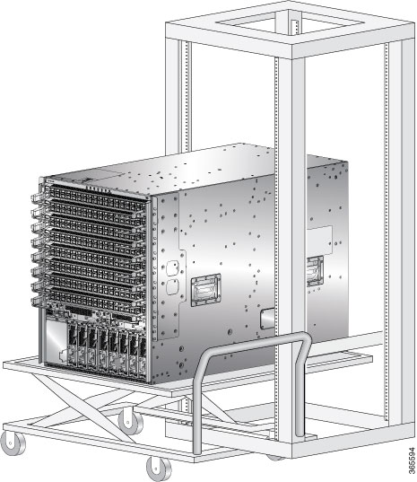
As an example of a suitable lifting device, the following figure shows a scissor lift raising the chassis.


Note


To lift the chassis, use a mechanical lift. Do not use the handles on the side of the chassis. Use the side handles for only repositioning the chassis after it is already on the mechanical lift or in the rack or cabinet.

Before you begin

Make sure that the rack is level and bolted to the floor.

Procedure


Step 1

Load the chassis onto a mechanical lift as follows:

  1. Position the mechanical lift next to the shipping pallet that holds the chassis.

  2. Elevate the lift platform to the level of the bottom of the chassis (or no more than 1/4 inch [0.635 cm] below the bottom of the chassis).

  3. Use at least two persons to slide the chassis fully onto the lift so that the side of the chassis touches or is close to the vertical rails on the lift. Make sure that the front and rear of the chassis are unobstructed so you can easily push the chassis into the rack.

Step 2

Using your mechanical lift, raise the chassis to the height of the rack's horizontal mounting rails. Elevate the lift platform to the level of the bottom of the chassis (or no more than 1/4 inch [0.635cm] below the bottom of the chassis).

Figure 5. Example - Use Scissor Lift to Position Chassis Rack

Step 3

Push the chassis halfway onto the rack or cabinet.

Use at least two persons to push the chassis onto the bottom-support rails and one person to guide the chassis down the center of the rails. Push the lower half of the front side of the chassis so that the back side enters the rack first, and push until the chassis is halfway onto the rack (see the following figure). Ensure that the chassis does not get caught on any of the expansion edges of the bottom-support rail.

Figure 6. Move Chassis onto a Rack

1

Push the sides of the lower half of the front side of the chassis.

3

Rack vertical mounting rails on the rack.

2

Chassis mounting brackets.

4

Bottom-support rails.

Tip

 
To adjust the placement of the chassis on the bottom-support rails, you can use the chassis handles (see Callout 1 in the figures).

Step 4

Push the chassis all the way onto the rack so that the vertical mounting brackets on the front of the chassis come in contact with the vertical mounting rails on the rack.

Step 5

Use four M6 x 19 mm or 24 x 3/4-inch screws to attach each of the two chassis vertical mounting brackets to the two rack vertical mounting rails (total of eight screws). See Callout 2 in the figures.

Figure 7. Attach NCS 5504 Chassis to Rack
Figure 8. Attach NCS 5508 Chassis to Rack
Figure 9. Attach NCS 5516 Chassis to Rack

1

Handles used to adjust chassis placement

2

Four M6 x 19 mm or 10-24 x 3/4 in. Phillips screws used to attach each side bracket to a front mounting rail (use a total of eight screws)


What to do next

After you have secured the chassis to the rack, you can connect the chassis to the data center ground.

To install the air filter or door kit, which is optional (see the (Optional) Install Air Filter, Cable Management Bracket, or Door Kit on a Chassis section).

(Optional) Install Air Filter, Cable Management Bracket, or Door Kit on a Chassis

Before you begin

The chassis must be installed and secured to the rack.

Required tools and equipment:

  • Phillips screwdriver with torque capability (customer supplied)

  • The following frames and screws (shipped with the optional door kit)

    • Two side brush filter frames (left and right)

    • One top hood frame

    • One lower hood frame

    • Door with filter

    • Ground Strap


Note


The Door kit (optional) also contains the air filter. The door kit can be ordered separately.


Table 1. Door and Screws Required for Installation

Door/Screws

NCS 5504

NCS 5508

NCS 5516

Door Kit PID

NCS-5504-DOOR=

NCS-5508-DOOR=

NCS-5516-DOOR=

M4x12 Flat Head, Phillip Screw

12

30

42

M3x12 Flat Head, Phillip Screw

18

20

28

M3x12 PAN Head, Phillip Screw

-

3

6

M3x8 PAN Head, Phillip Screw

3

-

-

M4x8 Flat Head, Phillip Screw

4

-

-


Note


The cable management brackets (optional), also referred to as side filter frames can be ordered separately. To install the cable management brackets follow the steps (Step 1 and Step 2) in this procedure, “(Optional) Install Air Filter, Cable Management Bracket, or Door Kit on a Chassis”. The PIDs for the cable management brackets are:

  • NCS-5504-CAB-MGMT=

  • NCS-5508-CAB-MGMT=

  • NCS-5516-CAB-MGMT=


To replace an existing air filter, you must order the air filter separately. The PIDs for the air filters are:

  • NCS-5504-FLTR=

  • NCS-5508-FLTR=

  • NCS-5516-FLTR=

Procedure


Step 1

Attach the two side extension brackets to the chassis as follows:

  1. Remove the screws from the bottom support rails. Save the screws for re-installation.

  2. Position one of the side extension brackets on the vertical mounting bracket and the bottom support rails so that the two screw holes are aligned.

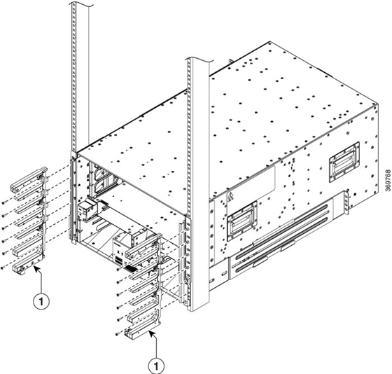
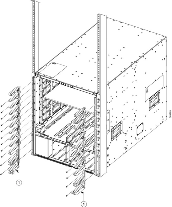
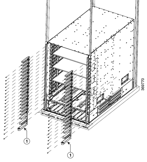
  3. Secure the extension bracket to the chassis vertical mounting bracket with M6 x 19 mm (or 12-24 X ¾ inch screws), pan-head, Phillips screws. Note that these are the screws you removed earlier in Step a. Tighten each screw to 40 in-lb (4.5 N·m) of torque. The number of screws can vary based on the chassis.

  4. Repeat Steps 1a - 1c to attach the other side of the extension bracket to the vertical mounting bracket on the opposite side of the chassis.

    Figure 10. Attach Two Side Extension Bracket on NCS 5504 Chassis
    Figure 11. Attach Two Side Extension Bracket on NCS 5508 Chassis
    Figure 12. Attach Two Side Extension Bracket on NCS 5516 Chassis

Step 2

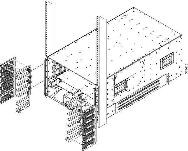
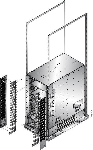
Attach the two side filter frame assemblies or the cable management brackets to the chassis as follows:

  1. Position one of the side frame assemblies on the vertical mounting bracket attached to one side of the front of the chassis.

    For NCS 5504: Ensure that the upper most 4 screw holes in the assembly align with the screw holes in 4 visible standoffs on the mounting bracket.

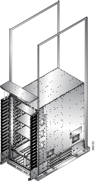
    Figure 13. Attach Side Filter Assembly or Cable Management Brackets to NCS 5504 Chassis

    For NCS 5508: Ensure that the 5 screw holes in the assembly align with the screw holes in five standoffs on the mounting bracket.

    Figure 14. Attach Side Filter Assembly or Cable Management Brackets to NCS 5508 Chassis

    For NCS 5516: Ensure that the 17 screw holes in the assembly align with the screw holes in 17 standoffs on the mounting bracket.

    Figure 15. Attach Side Filter Assembly or Cable Management Brackets to NCS 5516 Chassis

    1

    Cable Management Brackets or Side Filter Frames

  2. Secure the upper portion of the assembly to the chassis vertical mounting bracket.

    For NCS 5504: Use 12 M4 x 12 mm, flat-head, Phillips screws.

    For NCS 5508: Use 5 M4 x 12 mm, flat-head, Phillips screws.

    For NCS 5516: Use 17 M4 x 12 mm, flat-head, Phillips screws.

    Tighten each screw to 11.5 to 15 in-lb (1.3 to 1.7 N·m) of torque.
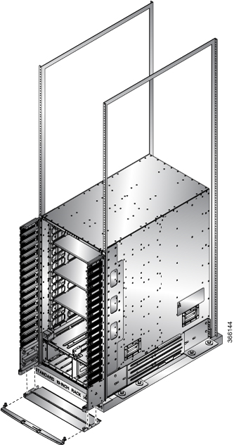
  3. Secure the bottom portion of the assembly to the chassis using two M4 x 12 MM flat-head Phillips screws in each of the two angled brackets on the assembly. Tighten each screw to 11.5 to 15 in-lb (1.3 to 1.7 N·m) of torque.

  4. Repeat Steps 2a and 2c to attach the other side filter frame assembly to the mounting bracket on the opposite side of the chassis.

Step 3

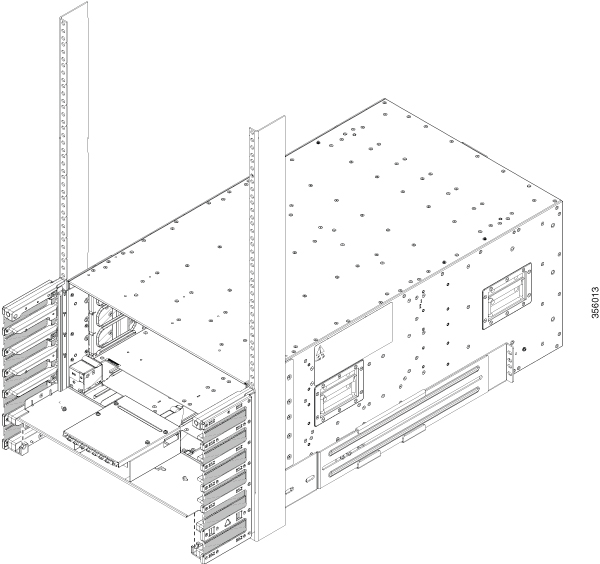
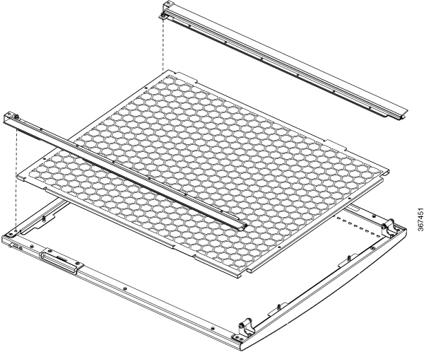
Attach the two air filters to the side filter frames as follows:

  1. Remove an air filter from its packaging and position it on the side frames.

    NCS 5504: Ensure that its 9 holes align with 9 screw holes in the side brush filter frame.

    NCS 5508: Ensure that its 10 holes align with 10 screw holes in the side brush filter frame.

    NCS 5516: Ensure that its 14 holes align with 14 screw holes in the side brush filter frame.

  2. Fasten the air filter to the side brush filter assembly.

    NCS 5504: Use 9 M3 x 12 mm screws.

    NCS 5508: Use 10 M3 x 12 mm screws.

    NCS 5516: Use 14 M3 x 12 mm screws.

  3. Tighten the M3 screws to 5 to 7 in-lb (0.56 to 0.79 N.m) of torque.

    Figure 16. Attach Side Filter Assembly to NCS 5504 Chassis
    Figure 17. Attach Side Filter Assembly to NCS 5508 Chassis


    Figure 18. Attach Side Filter Assembly to NCS 5516 Chassis
  4. Repeat Steps 3a through 3c to attach the other air filter to the side filter assembly on the other side of the chassis.

Step 4

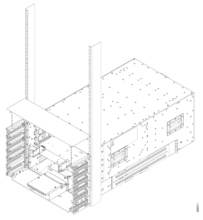
NCS 5504 and NCS 5508: Attach the bottom plate and top hood to the two side assemblies as follows:

Note


For NCS 5504, use 2 M3 x 8 mm pan head screws to secure the bottom plate.

Figure 19. Attach Bottom Plate to NCS 5504 Side Brush Filter Kit

Note


For NCS 5504, use 4 M4 x 8 mm flat head screws to secure the top hood.

Figure 20. Attach Top Hood to NCS 5504 Chassis and Side Brush Filter Kit
Figure 21. Attach Top Hood to NCS 5508 Chassis and Side Brush Filter Kit
  1. Place the bottom plate, with its brackets pointing up, to the bottom of the two side brush filter kit assemblies.

  2. Place the top hood, with its brackets pointing down, on top of the two side brush filter kit assemblies.

  3. (Only NCS 5504) Secure the bottom plate using 2 M3 x 8 mm pan head screws and top hood using 4 M4 x 8 mm flat head screws.

  4. (Only NCS 5508) Secure the bottom plate and top hood to the two side assemblies by using 8 M4 x 12 mm flat-head Phillips screws (use two screws for each assembly). Tighten each screw to 11.5 to 15 in-lb (1.3 to 1.7 N·m) of torque.

Step 5

NCS 5516: Attach the top hood to the chassis and the tops of the two side brush filter kit assemblies as follows:

Figure 22. Attach Top Hood to NCS 5516 Chassis and Side Brush Filter Assemblies
  1. Place the top hood, with its brackets pointing down, on top of the two side brush filter kit assemblies.

  2. Secure the top hood to the two side assemblies by using four M4 x 12 mm flat-head Phillips screws (use two screws for each assembly). Tighten each screw to 11.5 to 15 in-lb (1.3 to 1.7 N·m) of torque.

Step 6

Attach the divider bracket to the left and right side brush filter kit assemblies as follows:

  1. Position the divider bracket between the right and left side brush filter kit assemblies near the bottom of the chassis.

  2. Align the two slots on both sides of the bracket with the pins that stick out from the lower side brush filter kit frame and lower the bracket past the pins until the bracket stops.

  3. A screw hole on each side of the divider bracket aligns with a screw hole in each side brush filter kit assembly.

  4. Secure the divider bracket to both side brush filter kit assemblies using two M3 x 8 mm screws (one screw for each of two sides) and tightening the screws to 5 to 7 in-lb (0.56 to 0.79 N.m) of torque.

Step 7

(For NCS 5516 Only): Install the door-stop bracket on the top hood of the side brush filter kit frames by positioning the door-stop bracket to the bottom divider frame so that its two screw holes align to the two screw holes in the bottom divider. Ensure that there is a perpendicular edge facing the front. This edge stops the front doors when they are closed.

Figure 23. Install Door-Stop Bracket

Attach Front Door to NCS 5504 and NCS 5508 Chassis

Before you begin

Before you can attach the front door to the chassis, you must attach side filter frames, bottom divider bracket to the chassis.

Procedure


Step 1

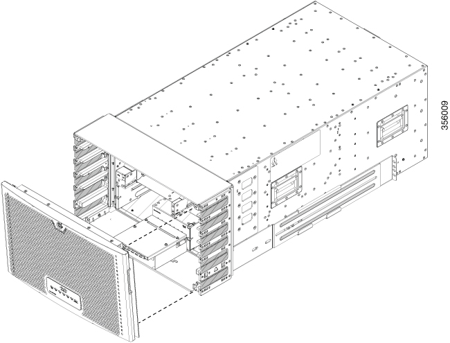
Place the two bars at the bottom of the front door on the two bar holders. Each bar holder is at the bottom of the side filter assembly.

Step 2

(NCS 5504) With the door resting on the bar holders, move the top of the door towards the top hood.

Step 3

(NCS 5508) With the door resting on the bar holders, rotate the top of the door to the top hood

The latch on the door will slide and lock in-position.

Figure 24. Attach Front Door to NCS 5504 Chassis
Figure 25. Attach Front Door to NCS 5508 Chassis

Attach Front Door to NCS 5516 Chassis

Procedure


Step 1

On the back side (open side) of one door, pull in on two protruding spring pins so that the pins are held inside the door frame.

Figure 26. Attach Front Door to NCS 5516 Chassis

Hold these two pins in through the next step.

Step 2

Align the spring pins to holes in the top hood and divider bracket.

Step 3

Release the two spring pins so that they insert into the holes in the top hood and divider brackets. The door should freely swing on the spring pins.

Step 4

Repeat Steps 1 through 3 to install the other front door.


Replace Chassis Door Foam Air Filters on the NCS 5504


Note


In general, we recommend that you inspect the air filter every 3 months and replace, if necessary, every 6 months.

The front doors come with pre-installed air filters. If air filters need replacement, follow this procedure.

Procedure


Step 1

Remove existing door filter and side brush brackets as follows:

  1. Remove the front door.

  2. Remove the side brush brackets by unscrewing the captive screws at the top of each brush bracket.

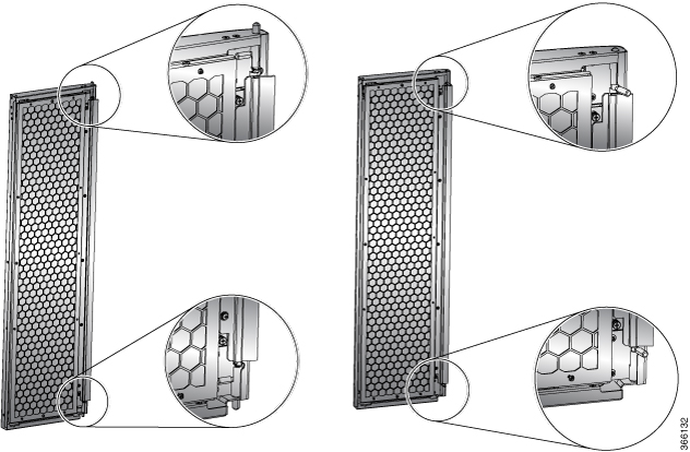
  3. Pull the foam air filter away from the snap-top alignment pins (two on the top and two on the bottom of the door).

Step 2

Install the new door filter as follows:

  1. Align the 4 alignment holes on to the filter to the 4 alignment pins on the door.

    Figure 27. Align Door Filter to the Door

    1

    Side brush bracket

    2

    Side brush bracket screws

  2. Press the filter onto the alignment pins.

  3. Install the side brush brackets and tighten the captive screws to secure the filter to the door.


What to do next

Ground the Front ID Door

Replace Chassis Door Foam Air Filters on the NCS 5508


Note


In general, we recommend that you inspect the air filter every 3 months and replace, if necessary, every 6 months.

The front doors come with pre-installed air filters. If air filters need replacement, follow this procedure.

Procedure


Step 1

Remove existing door filter and side brush filters as follows:

  1. Remove the front door.

  2. Remove the side brush filters by unscrewing the captive screws at the top of each brush filter.

  3. Pull the foam air filter directly away from the door to clear of the snap-top alignment pins (two on the top, two on the side and two on the bottom of the door).

Step 2

Install the new door filter as follows:

  1. Align the 4 alignment holes on to the filter to the 4 alignment studs on the door.

    Figure 28. Align Door Filter to the Door
  2. Press the filter onto the alignment studs.

  3. Install the side brush filters and use 2 screws to secure the filter to the door.


Replace Chassis Door Foam Air Filters on the NCS 5516


Note


In general, we recommend that you inspect the air filter every 3 months and replace, if necessary, every 6 months.

The front doors come with pre-installed air filters. If air filters need replacement, follow this procedure.

Procedure


Step 1

Remove existing two door filters and two door-side filters on the two front doors as follows:

  1. Open the front doors and keep it in open position.

  2. Remove the door-side brush filter by unscrewing the captive screws on both ends of the filter.

  3. Remove the 3x screws securing the foam air filters.

  4. Pull the foam air filter directly away from the door to clear of the snap-top alignment pins (two on the top, two on the side and two on the bottom of the door).

Step 2

Install the two new door filters and two door-side filters on the two front doors as follows:

  1. Align the six alignment holes on the largest filter to six alignment studs on the open side of the door.

    Figure 29. Align Door Filter to a Door

    1

    Front door back side facing up

    2

    Air filter for inside of door

    3

    Alignmnent pins (two on top, side and bottom of the door)

    4

    Three screws used to secure filter to the the door

    5

    Air filter for side of the door

    6

    Captive screws one on each end

    7

    Screw hole for captive screw on filter

  2. Press the filter onto the alignment studs and use three #6-32 x 0.25” screws to secure the filter to the door.

Step 3

Repeat Steps 2a through 2b to install the air filters to the other front door.


What to do next

Ground the Front ID Door

Ground the Front ID Door


Note


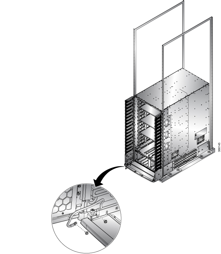
To comply with GR-1089, you have to bond the front ID door to the ground port on the chassis using the ground braid.

Procedure


Step 1

Install the grounding cable to the right side of the front ID door.

Step 2

Apply the star ring terminal end of the grounding cable to the front ID door. Tighten the screw to 7 in-lb (0.79 N-m) of torque to provide proper bonding.

Figure 30. Ground the NCS 5504 Front ID Door
Figure 31. Ground the NCS 5508 Front ID Door
Figure 32. Ground NCS 5516 Front ID Door

Step 3

Connect the other round terminal of the grounding cable to the ground port on the side filter bracket on either left/right side of the chassis. Tighten the M4 screw to 9 to 12 in-lb (1.01 to 1.35 N-m) of torque.

Step 4

Repeat Steps 1 through 3 to install the grounding cable to the other front door.

Step 5

Close and lock the front ID door.


What to do next

Locate and Ground the Chassis

Locate and Ground the Chassis

Procedure


Step 1

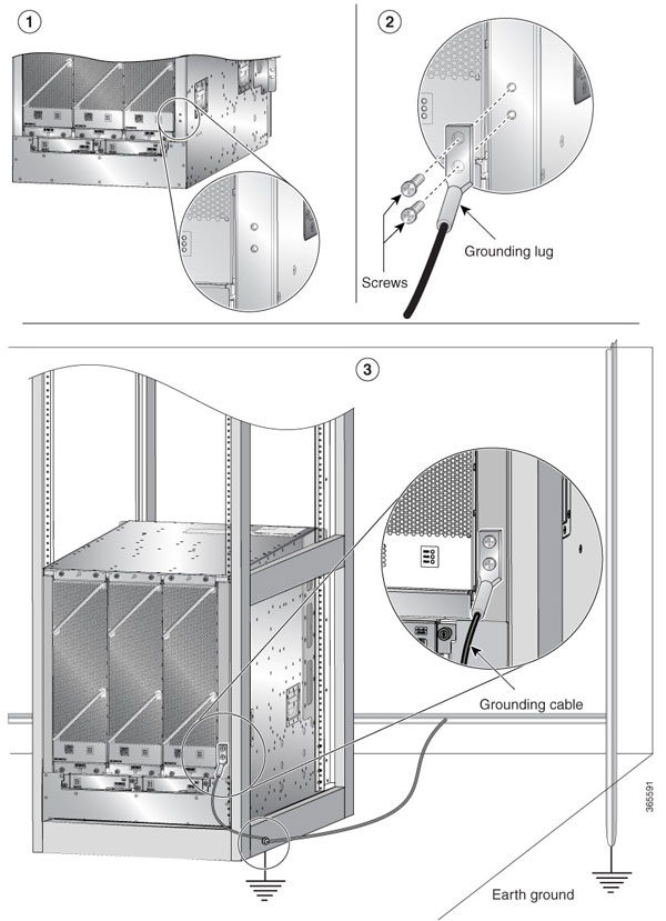
Locate the chassis grounding receptacles on your router chassis.

Figure 33. Grounding Lug— Cisco NCS 5508 or Cisco NCS 5516

Step 2

(Only NCS 5508 and NCS 5516) Insert the two screws through the holes in the grounding lug. Ensure that the grounding lug does not interfere with other router hardware, such as power supplies or the network processing engine.

(Only NCS 5504) Insert one screw through the hole in the grounding lug. Ensure that the grounding lug does not interfere with other router hardware, such as power supplies or the network processing engine.

Figure 34. Grounding Lug— Cisco NCS 5504

Step 3

Use the Phillips screwdriver to carefully tighten the screws until the grounding lug is held firmly to the chassis. Do not overtighten the screws.

Step 4

Use the wire stripper to strip one end of the 6-AWG wire approximately 0.75 inches (19.05 mm).

Step 5

Insert the 6-AWG wire into the wire receptacle on the grounding lug.

Step 6

Use the crimping tool to carefully crimp the wire receptacle around the wire; this step is required to ensure a proper mechanical connection.

Step 7

Connect the opposite end of the grounding wire to the appropriate grounding point at your site to ensure an adequate chassis ground.


What to do next

Continue to start up the router.

Connect AC Power Supply to AC Power Source

Before you begin

See Weight, Quantity and Power Consumption to ascertain the power needs for the router.


Note


Take care when connecting units to the supply circuit so that wiring is not overloaded.


Procedure


Step 1

For each 3-kW Standard AC power supply, connect an AC power cable to the AC power source and to the power receptacle on the power supply.

Figure 35. Connect AC Power Supply to AC Source

Step 2

Verify that the Output Power OK LED turns on and becomes green.


What to do next

Connect the router to the network.

Connect 3kW DC Power Supply to DC Power Source

For n+1 power redundancy or no power redundancy, connect all of the power supplies in the switch to the same power grid. For n+n power redundancy, connect n power supplies to separate power grids (example: grid A power supplies on the left side of the switch, grid B power supplies on the right side of the switch).

Before you begin

  • Install the power supplies in the chassis.

  • Ensure that power is removed from the DC circuit.

  • The power supplies must be close enough to be connected to the DC power source using the customer-provided power cables.

  • Four 6-AWG lugs provided with the power supply.

  • Customer-provided equipment and tools must include all of the following:

    • Four power cables (6 AWG cables recommended)


      Note


      If you use colors to designate positive and negative cables, you need two cables colored for positive polarity and two cables colored for negative polarity.
    • Wire stripping tool

    • Crimping tool

    • Torque screwdriver and wrench

Procedure


Step 1

Turn off the switch and circuit breaker as follows:

  1. Turn the power switch on the power supply to standby (labeled 0 on the power supply).

  2. Turn off the circuit breaker for each of the two power inputs coming from the DC power source.

Step 2

Connect the four customer-provided power cables to the power supply and power source as follows:

  1. Use a wire stripper to remove 0.75 inches (19 cm) of insulation from the end of each of four power cables.

  2. Use a crimping tool to attach each of four lugs (provided with the chassis for each power supply) to the stripped end of each cable. Test each crimped lug by trying to pull it off its cable.

  3. Use a torque screwdriver to unscrew three screws on the cover for the terminal box that is located on the front of the power supply and lift off the cover as shown in the following figure.

    Note

     
    The terminal box has four slots for four power terminals (ordered as negative [-], positive [+], positive [+], and negative [-]). Each terminal has two nuts that you use to fasten a power cable to the terminal.
  4. Remove the two nuts from each terminal post in each slot of the terminal box.

  5. Place each of the lugs for the two positive cables on the terminal posts for the positive slots (two middle slots) of the terminal box and fasten each lug using two nuts tightened to 40 in-lb (4.5 N·m) of torque.

  6. Place each of the lugs for the two negative cables on the terminal posts for the negative slots (two outside slots) of the terminal box and fasten each lug using two nuts tightened to 40 in-lb (4.5 N·m) of torque.

  7. Replace the safety cover on the terminal box and fasten it in place using its three screws.

  8. Connect the other ends of the power cables to the two DC power circuits. Be sure that the positive and negative cables attached to one side of the power supply are attached to the same DC power source circuit (with the negative cable attached to a negative terminal and with the positive cable attached to a positive terminal).

Step 3

Power up the power supply as follows:

  1. Turn on the power source circuit breaker for both input lines. Verify that the Input 1 (IN1) and Input 2 (IN2) LEDs light up on the power supply.

  2. Turn the power switch on the power supply to ON (labeled 1 on the power supply). The LEDs should flash and then the OK LED should turn on (green) in addition to the Input LEDs.


Connect 4.4kW DC Power Supply to DC Power Source

For n+1 power redundancy or no power redundancy, connect all of the power supplies in the switch to the same power grid. For n+n power redundancy, connect n power supplies to separate power grids (example: grid A power supplies to IN1, grid B power supplies to IN2, and so on).

Before you begin

  • Ensure that power is removed from the DC circuit.

  • The power supplies must be close enough to be connected to the DC power source using the customer-provided power cables.

  • Six lugs of 6-AWG provided with the power supply.

  • Customer-provided equipment and tools must include all the following:

    • Six power cables (6 AWG cables recommended)


      Note


      If you use colors to designate positive and negative cables, you need three colored cables for positive polarity and three colored cables for negative polarity.
    • Wire stripping tool

    • Crimping tool

    • Torque screwdriver and wrench

Procedure


Step 1

Turn off the switch and circuit breaker as follows:

  1. Turn the power switch on the power supply to standby (labeled 0 on the power supply).

  2. Turn off the circuit breaker for each of the three power inputs coming from the DC power source.

Step 2

Connect the six customer-provided power cables to the power supply and power source as follows:

  1. Use a wire stripper to remove 0.75 inches (19 cm) of insulation from the end of each of six power cables. If you are using different colored cables for positive and negative polarity, be sure that you have three of each color (three positive cables and three negative cables).

  2. Use a crimping tool to attach each of six lugs (provided with the chassis for each power supply) to the stripped end of each cable. Test each crimped lug by trying to pull it off its cable. This ensures that the cable is crimped properly to the lug.

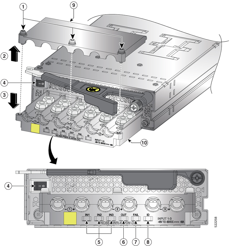
  3. Use a torque screwdriver to unscrew three screws, marked as 1, on the cover of the terminal box that is located on the front of the power supply. Then, lift off the safety cover in upward direction, marked as 2, as shown in the following figure.

    Figure 36. NC55-PWR-4.4KW-DC Power Supply Unit
    1 Screws 7 FAIL LED. Glows solid amber to indicate Power Supply failure. Power supply failure reason can be one of the following:
    • over voltage

    • over current

    • over temperature

    • fan failure

    4 Power Switch. 1 is ON and 0 is OFF. 8 ID LED. Blinks with blue color at 1Hz when PMBus Command (E0) is executed.

    5

    Input 1,2,3 (IN1, IN2, IN3) LEDs. Glows solid green when the corresponding feed in ON.

    9 Safety cover
    6 OUT LED. Glows solid green to indicate that the Power Supply is ON and OK.

    10

    Terminal box

    Note

     
    The terminal box has six slots for six power terminals (ordered as negative [-], positive [+], negative [-], positive [+], negative [-], and positive [+]). Each terminal has two nuts that you use to fasten the lug that is attached to a power cable to the terminal.
  4. Remove the two nuts from each terminal post in each slot of the terminal box.

  5. Place each of the lugs for the three positive cables on the terminal posts for the positive slots of the terminal box and fasten each lug by using two nuts tightened to 40 in-lb (4.5 N·m) of torque.

  6. Place each of the lugs for the three negative cables on the terminal posts for the negative slots of the terminal box and fasten each lug using two nuts tightened to 40 in-lb (4.5 N·m) of torque.

  7. Replace the safety cover on the terminal box in the downward direction, marked as 3 in the figure, and fasten it in place using its three screws.

  8. Install the power supplies in the chassis.

  9. Connect the other ends of the power cables to the three DC power circuits. Ensure that the positive and negative cables that are attached to one side of the power supply are attached to the same DC power source circuit. With the negative cable attached to a negative terminal and the positive cable attached to a positive terminal.

Step 3

Power up the power supply as follows:

  1. Turn on the power source circuit breaker for all the three input lines. Verify that Input 1 (IN1), Input 2 (IN2), and Input 3 (IN3) LEDs light up on the power supply.

  2. Turn the power switch on the power supply to ON (labeled 1 on the power supply). The LEDs must flash and then the OK LED must turn on (green) in addition to the Input LEDs.


Connect HVAC/HVDC Power Supply to Power Source

The HVAC/HVDC power supply (NC55-PWR-3KW-2HV) has 2 redundant input power lines. It can provide power output at 3.15KW with either 1 or 2 input power lines operating. The HVAC/HVDC power supply provides n+n or n+x line redundancy mode in a single power supply for the NCS 5500 series modular routers.

The HVAC/HVDC power supply accepts 200–240VAC or 240/380VDC input power.

If you are not using power redundancy or are using n+1 power redundancy, you can connect all of the power supplies in the chassis to the same power grid. If you are using n+n power redundancy, connect one set of the power supply inputs to one power grid and the other set of the power supply inputs to another power grid (for example, connect grid A to the receptacles closest to the power switch on the power supplies, and connect grid B to the receptacles furthest from the power switch on the power supplies).


Note


You can have a mix of AC power supplies and HVAC/HVDC power supplies in a chassis.

Before you begin

  • The AC or DC power source must be turned off at its circuit breaker.

  • The power switch on the power supply must be turned off (power switch set to 0).

  • The AC power sources are rated as follows:

    • For North American installations—20A with 200-240V circuits.

    • For international installations—size the circuits by local and national standards.

Procedure


Step 1

For AC input, connect an AC power cable to the AC power source.

Step 2

For DC input, connect a Saf-D-Grid/Saf-D-Grid DC cable to a Saf-D-Grid receptacle, otherwise:

  1. Connect the ground terminal ring on the power cable to the ground terminal on the DC power source and secure it in place with a nut tightened to the appropriate torque setting for the terminal post.

  2. Connect the negative terminal ring on the power cable to the negative (-) terminal on the DC power source and secure it in place with a nut tightened to the appropriate torque setting for the terminal post.

  3. Connect the positive terminal ring on the power cable to the negative (+) terminal on the DC power source and secure it in place with a nut tightened to the appropriate torque setting for the terminal post.

Step 3

Connect the Saf-D-Grid connector on the other end of the power cable to the Saf-D-Grid receptacle on the power supply.

Step 4

Turn on the circuit breaker for the DC power source circuit.

Step 5

Turn on the power supply by pressing its power switch to on (1).

Step 6

Verify that the OUT LED turns on and becomes green.

Note

 
If you use both inputs, the IN LED is green. If you use only one input, the IN LED is blinking green.

What to do next

Use the power-mgmt redundancy-num-pms number command in System Admin Config mode to convert the power module redundancy from n+1 to n+x, specifying the number of redundant power modules that the you want to configure. The total number of functioning power modules in the system is at least x number more than the number of power modules needed to support the power required for all the cards in the system. The range is from 0 to 5; 0 means no power redundancy is required.

sysadmin-vm:0_RP0# config
sysadmin-vm:0_RP0(config)# power-mgmt redundancy-num-pms 2
sysadmin-vm:0_RP0(config)# commit
Tue Sep  3  12:17:53.891 UTC
Commit complete.

Use the [no] hw-module attention-led location 0/PMnumber command in System Admin Config mode to enable or disable the ID LED on the specified power supply.


sysadmin-vm:0_RP0# config
sysadmin-vm:0_RP0(config)# hw-module attention-led location 0/PM2
sysadmin-vm:0_RP0(config-location-0/PM2)# commit
Tue Aug  27 18:59:28.740 UTC
Commit complete.
sysadmin-vm:0_RP0(config-location-0/PM2)# end

sysadmin-vm:0_RP0# show led location 0/PM2
Tue Aug  27 18:59:59.723 UTC
=============================================================
Location  LED Name                      Mode         Color
=============================================================
0/PM2
         0/PM2-FAIL                     WORKING     OFF
         0/PM2-IN                       WORKING     GREEN
         0/PM2-OUT                      WORKING     GREEN
         0/PM2-ATTENTION (ID)           WORKING     BLINKING BLUE