Prior to Release 11, Cisco DCNM Media Controller performed operations such as managing the bandwidth, stitching the flows,
host link bandwidth, and so on. Beginning with Release 11, DCNM allows two major operations.
DCNM monitors the Flow Status, Discovered Host, Applied Host Policies, and other operations using Telemetry. For any operations
triggered by the switch and received through telemetry (e.g. Flow Established), DCNM periodically checks for new events and
generate appropriate notification.
If pmn.deploy-on-import-reload.enabled server property is set to true, during a switch reload, when DCNM receives switch coldStartSNMPtrap, it will push Global
Config, and Host and Flow policies that are showing 'Deployment Status=Successes' to the switch automatically. The switch
telemetry and SNMP configuration can be deployed on demand by using DCNM packaged pmn_telemetry_snmp CLI template via Configure > Templates > Template Library.
Navigate to Cisco DCNM Web UI > Media Controller > Global > Config to set or modify Switch Global configuration and WAN links.
When DCNM is installed in Media Controller Deployment mode, you can deploy policies the unicast bandwidth, Any Source Multicast
(ASM) range, and WAN links through Web UI > Media Controller > Global > Config.
After you deploy the DCNM in Media Controller mode, configure the bandwidth and ASM. The remaining percentage of the bandwidth
is utilized by the multicast traffic. DCNM acts like a Master Controller, and deploy the bandwidth and ASM configurations
to all the switches in the fabric.
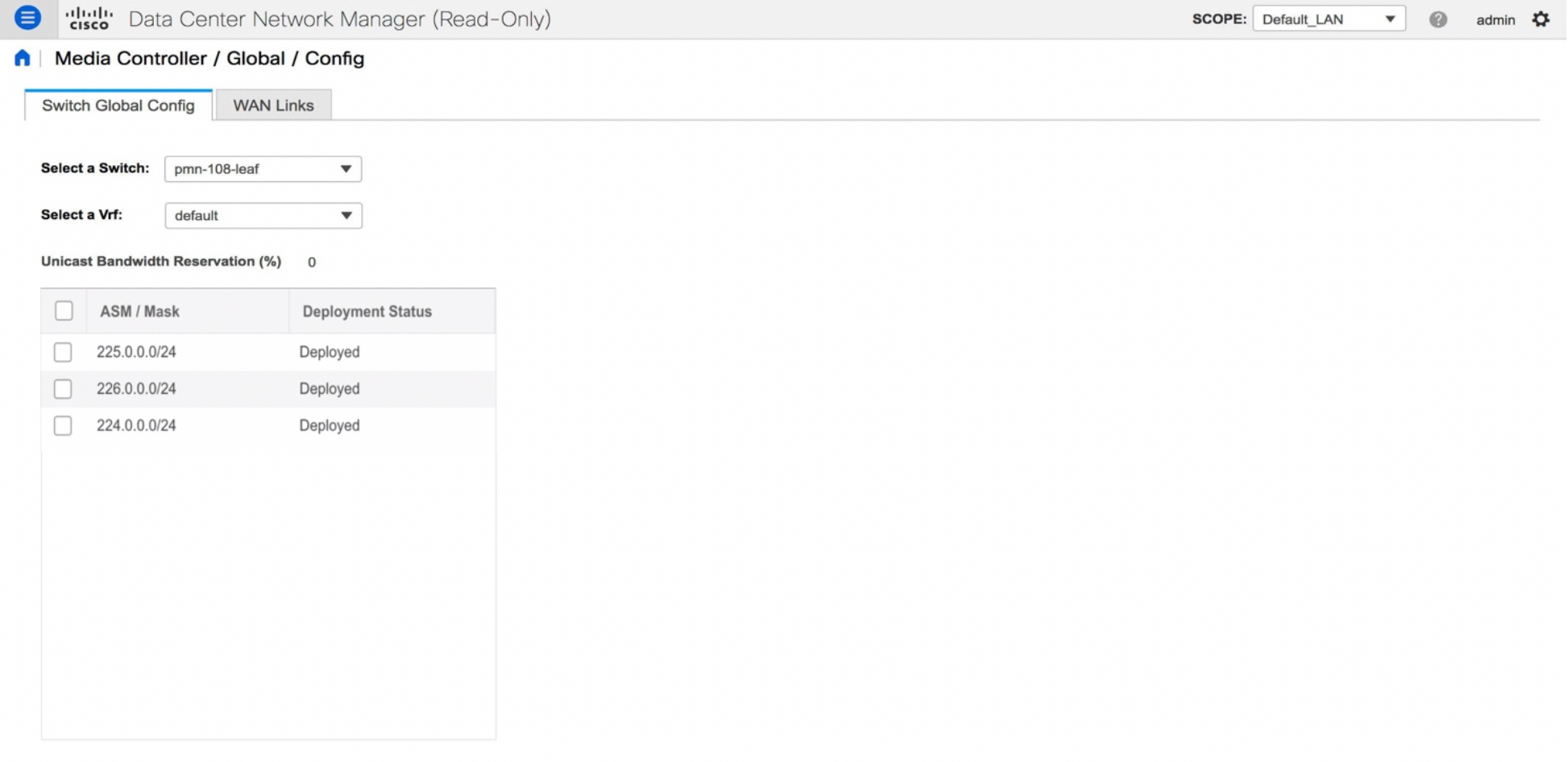
Navigate to Cisco DCNM Web UI > Media Controller > Global > Config > Switch Global Config to configure the global parameters.

Note |
A user with the network operator role in DCNM cannot save, deploy, undeploy, add or delete ASM, or edit the unicast bandwidth
reservation percentage.
|
AMQP Notifications
As Cisco DCNM uses Telemetry to fetch data from the Fabric, the flow status and AMQP notifications may not reflect the current
state in real time. It periodically checks new events and generate appropriate notification. Also, flows are no longer limited
to a single spine and may take N or W or M shape. Host policies are applied based on the switch interface configuration and
not just-in-time (JIT). All these architecture changes influence current AMQP messages and trigger time. By default, poll
interval is set to 2 minutes. For more information, see AMQP Notifications.
Unicast Bandwidth Reservation
You can configure the server to allot a dedicated percentage of bandwidth to unicast traffic. The remaining percentage is
automatically reserved for multicast traffic.
In the Unicast Bandwidth Reservation (%) field, enter a numeric value to configure the bandwidth.
Reserve Bandwidth to Receiver Only
In previous DCNM releases, switch always used to pull ASM traffic to spine to cut down flow set up time. However, this unnecessarily
occupies spine bandwidth if there are no active receivers. From Cisco DCNM Release 11.4(1), you can check the Reserve Bandwidth to Receiver Only check box to push the ASM traffic to spine only if there is a receiver. This feature is applicable for switches with the
Cisco NX-OS Release 9.3(5) and later.
ASM Range
Any Source Multicast (ASM) is a PIM tree building mode that uses shared trees to discover new sources and receivers as well
as source trees to form shortest paths from receivers to sources. ASM provides discovery of multicast sources.
You can configure the ASM range by specifying the IP address and the subnet mask.
In the ASM/Mask field, enter the IP address and subnet mask defining the multicast source. Click Add icon to add the multicast address to the ASM range. You can add multiple ASM ranges. To delete an ASM range, select the check
box next to the ASM/Mask in the table and click Delete icon.
After you configure the Unicast Bandwidth Reservation and ASM range, you can perform the following operations to deploy these
configurations to the switches.
Table 25. Operations on the Global Config screen
|
Icon
|
Description
|
|
Save
|
Click Save to save the configurations.
|
|
Deploy
|
To deploy the configuration, you can choose one of the following from the drop-down list:
-
All—Deploys ASM, unicast bandwidth, and reserved bandwidth configuration to all switches.
-
Unicast BW—Deploys only unicast bandwidth configuration.
-
Reserve BW—Deploys only the reserve bandwidth configuration.
-
ASM—Deploys only the ASM configuration.
-
All Failed—Deploys all failed deployments.
Success or Failed message appears next to each of the ASM range in the table.
|
|
Undeploy
|
To undeploy the configuration, you can choose one of the following from the drop-down list:
-
All—Undeploys ASM, unicast bandwidth, and reserved bandwidth configuration to all switches.
-
Unicast BW—Undeploys only unicast bandwidth configuration.
-
Reserve BW—Undeploys only the reserve bandwidth configuration.
-
ASM—Undeploys only the ASM configuration.
|
|
Status
|
Bandwidth reservation status specifies if the bandwidth deployment was success, or failed or not deployed.
ASM/Mask Status field displays if the ASM and Mask configuration was deployed successfully, or failed or not deployed.
|
|
History
|
Click the respective History link to view the deployment history for Unicast Bandwidth and ASM deployments.
|
The following table describes the fields that appear on the Deployment History.
Table 26. Deployment History Field and Description
|
Field
|
Description
|
|
Switch Name
|
Specifies the switch name in the fabric on which the configuration was deployed.
|
|
Action
|
Specifies the action that is performed on the switch-Deploy or Undeploy.
|
|
Deployment Status
|
Displays the status of deployment. It shows if the deployment was Success or Failed.
|
|
Deployment Date/Time
|
Displays the date and time when the deployment was initialized.
|
|
Failed Reason
|
Specifies the reason why the deployment failed.
|
|
Show
|
From the drop-down list, choose an appropriate filter.
-
Quick Filter - A search field appears in every column. You can enter a search string to filter.
-
Advanced Filter - In the Advanced Filter screen, select the All or Any radio button in the Match field. In the Select Filter
field, select the category from the drop-down list. Select an appropriate condition from the drop-down field in the next field.
Enter a search string in the next field.
Click Add icon to add another filter. Click Remove icon to delete the filter. Click Clear to clear all the filters. Click Apply to activate the filters, and view the filtered events. Click Save to save the applied filter. Click Cancel to discard the advanced filters.
-
All - This removes all the filters and displays the complete deployment history.
-
Manage Preset Filters - Select an appropriate filter from the drop-down list.
Click Edit to modify the filter parameters. Click Remove to delete the filter. Click Cancel to discard the changes and revert to Deployment History.
|
|
Total
|
Displays the total number of events on the Deployment History page.
|
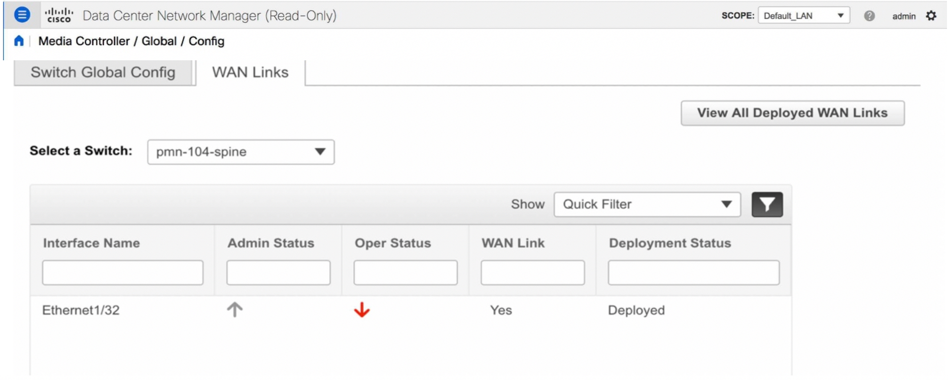
After deploying the global configurations, configure the WAN for each switch in your network.








 Feedback